THE DESIGN OF AN EFFICIENT LOAD BALANCING ALGORITHM EMPLOYING BLOCK DESIGN
Ilyong Chung and Yongeun Bae
Abstract. In order to maintain load balancing in a distributed system, we should obtain workload information from all the nodes on network. This pro-cessing requiresO(v2) communication overhead, wherevis the number of nodes.
In this paper, we present a new synchronous dynamic distributed load balancing algorithm on a (v, k+ 1,1)-configured network applying a symmetric balanced incomplete block design, wherev=k2+k+ 1. Our algorithm needs onlyO(v√v)
communication overhead and each node receives workload information from all the nodes without redundancy. Therefore, load balancing is maintained since every link has the same amount of traffic for transferring workload information.
AMS Mathematics Subject Classification : 68Q25
Key words and phrases: Load balancing, block design
1. Introduction
In a distributed system it is likely that some processors are heavily loaded while some are lightly loaded or idle. It is desirable that workload be balanced between these processors so that utilization of processors can be increased and re-sponse time can be reduced. A load balancing scheme[1]-[2] determines whether a task should be executed locally or by a remote processor. This decision can be made in a centralized or distributed manner. In a distributed system, distributed manner is recommended.
In order to make this decision, each node can be informed about the workload information of other nodes. Also this information should be the latest because outdated information may cause an inconsistent view of the system state.
So disseminating load information may incur a high link cost or a significant communication traffic overhead. In order to decrease communication overhead for obtaining workload information, the message is exchanged between adjacent
Received July 11, 2003. c
2004 korean Society for Computational & Applied Mathematics and Korean SIGCAM.
nodes and local load-balancing process is performed repeatedly. Then it makes the whole system be load-balancing[3]-[4].
It is accomplished by employing CWA(Cube Walking Algorithm) on hy-percube network, which utilizes workload information of all the nodes. This method requiresO(v2) communication complexity and a communication path is O(log2v).
To reduce communication cost, flooding scheme is applied. However, the over-lap of transmitting information occurs[5]-[6]. Based on SBN(Symmetric Broad-cast Networks), communication patterns between nodes are constructed. It also needsO(v2) communication complexity for collecting workload information from all the nodes and a communication path isO(log2v)[7]-[8].
In this paper we present the network topology consisting ofvnodes andv×k links and each node of which is linked to 2knodes, wherev=k2+k+ 1. On this network, each node sends workload information ofk nodes tok adjacent nodes periodically. In other words, each node receives information fromk nodes and sends information toknodes.
Also there is no redundancy in this received information. So, each node re-ceives workload information fork2+knodes with two round message interchange. Therefore load balancing in this algorithm is maintained so that every link has has the same amount of traffic.
2. About (v,k, λ )-configuration
LetV ={0,1 , ... ,v−1}be a set ofvelements. LetB ={B0, B1, ..., Bb−1}be a set ofbblocks, whereBiis a subset ofV and |Bi|=k. For a finite incidence
structure σ ={V, B} , ifσ satisfies following conditions, then it is a balanced incomplete block design(BIBD)[9], which is called a (b,v,r,k,λ)-configuration.
1. B is a collection of b k-subsets of V and thesek-subsets are called the blocks.
2. Each element of V is related with exactlyrofb blocks.
3. Every two objects ofV appears simultaneously in exactlyλofb blocks. 4. k < v
For a (b,v,r,k,λ)-configuration, if it satisfies k = r and b = v, then it is a symmetric balanced incomplete block design (SBIBD)[10] and it is called a (v, k, λ)-configuration.
There are some relations among parameters b, v, r, k, λ that are necessory conditions for existence of this configuration,bk=vr andr(k−1) =λ(v−1).
We now present an algorithm to generate an incidence structureσ={V, B}
satisfying the condition for a (v, k+ 1,1)-configuration in the case that k is a prime number. This (v, k+ 1,1) -configuration is employed for constructing network topology below.
3.1. Design of an algorithm to construct (v,k+1, 1)-configuration
Algorithm 1for Generating an incidence structure.
Incidence structure T ={V, B}, where V = {0,1 , ... ,v−1}, B={B0, B1, ..., Bb−1}, |Bi|=k+ 1. Bi,j is the jth element of Bi
1. Select a prime number k and compute v=k2+k+ 1.
2. Construct two incidence structures X ={V, C} and Y ={V, D}.
(a) Ci,j, 0≤i, j≤k, has a value as following.
Ci,j=
0 if j= 0
t, t=i×k+j if j≥1 (b) Di,j, 0≤i≤(k2−1), 0≤j≤k, has a value
as following.
Di,j= C0
,t, t=bi/kc+ 1 if j= 0
Cj,t, t= (i+ (j−1)× bi/kc) mod k+ 1 if j≥1
3. Generate Z={V, B} from X and Y. Bi ←− Ci
Bi+k+1 ←− Di
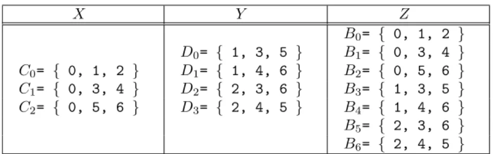
The table below illustrates how to create Z ={V, B}, V ={0,1, ... ,6}. We now prove that this structure satisfies the conditions of a (v, k+ 1,1)-configuration.
TABLE 1. A set of blocks onZ generated from algorithm 1 X Y Z B0= { 0, 1, 2 } D0= { 1, 3, 5 } B1= { 0, 3, 4 } C0= { 0, 1, 2 } D1= { 1, 4, 6 } B2= { 0, 5, 6 } C1= { 0, 3, 4 } D2= { 2, 3, 6 } B3= { 1, 3, 5 } C2= { 0, 5, 6 } D3= { 2, 4, 5 } B4= { 1, 4, 6 } B5= { 2, 3, 6 } B6= { 2, 4, 5 }
Definition 1. On incidence structureY, SectorSiis theithfamily ofkblocks,
Dj ∈Si,i=bj/kc.
For example, if k equals 3 , then b0/kc = b1/kc = b2/kc = 0. So, S0 =
{D0, D1, D2}. There arek sectors inY.
Lemma 1. For two elementsDi1,j1and Di2,j2,Di1,j16=Di2,j2, if j16=j2.
P roof.From Algorithm 1-2-(a), if 0< j≤k, 0≤i≤kthenCi,j=i×k+j. This
means if j >0 then all the elements are distinct. And as shown in Algorithm 1-2-(b), an element of Cj is placed on jth element of a certain block of Y if
Di,j =Cj,t, t6= 0.
Lemma 2. For a sector consisting ofk blocks, the first element of each block has the same value and the otherk2elements are equal toV −C0.
P roof. In the case that Di,0 =C0,bi/kc+1] , the first element ofk blocks on a sector have the same value. According to Algorithm 1-2-(b), Di,j = Cj,t, t =
(i+ (j−1)bi/kc)mod k+ 1. Sincekis a prime number, each element except the first element of each block is distinct and these distinctk2elements are equal to
V −C0.
Lemma 3. For incidence structure Y, Da,j =Db,j, j ≥1 , if b= ((a−c(j−
1))mod k +k(ba/kc+c))mod k2.
P roof. From Algorithm 1-2-(b),Da,j =Cj,t. We now prove thatDb,j=Cj,t. t
can be calculated from parametersb, j below. Thentobtained on this lemma is equal to that from Algorithm 1-2-(b). Therefore,Da,j =Db,j.
t= (b+ (j−1)× bb/kc)mod k+ 1
k(ba/kc+c))/kc)mod k+ 1
= (((a−c(j−1)) + (j−1)×(ba/kc+c)mod k+ 1 = (a+ (j−1)ba/kc)mod k+ 1
Here, if Da,j is in sector Ss then Db,j is in S(s+c)mod k. In case of c ≡
0 (mod k), thena=b.
Lemma 4. Each element ofV appears in exactlyk+ 1 times inZ.
P roof. According to Algorithm 1-2-(a), Ci,0 = 0. Since 0 ≤ i≤ k, 0 appears k+ 1 times. The otherv−1 elements,V − {0}, appear exactly once on X. From Lemma 3, each element ofC0,j,1≤j ≤kappearsktimes in a sector ofY and
the rest k2 elements appear once in every sector of Y. Therefore, each element
appearsk+ 1 times in Z.
Lemma 5. Any pair of elements ofV appears in exactly only once inZ.
P roof. The first element of V makes a pair with all the other elements and this pair appears once by designing rule of incidence structure(see Algorithm 1-2-(a)). Each elements ofC0,j,1≤j ≤k makes a pair with V −C0 elements
and it also appears once proven by Lemma 3. The rest k2 elements are now considered. For an arbitrary pair Da,j1 = Da,j2, j1, j2 ≥1, in order to make
the same pair on other blockDb, the two elements should be on the same block.
According to Lemma 4, ifj1 =j2, then they are located onDb. However, this
case does not occur sincej16=j2. Therefore, any pair of elements ofV appears
in exactly only one time inZ.
Therorem 1. Zdesigned by Algorithm 1 satisfies the conditions of a (v, k+1, 1)-configuration.
P roof. Z satisfied the conditions of the SBIBD by emplying Lemma 4 and
Lemma 5.
3.2. Design of Network Configuration
In order to construct a network topology which have minimum link cost and traffic overhead, we imported (v, k+ 1,1)-configuration. An incidence structure Z ={V, B}satifies the conditions for a (v, k+ 1,1)-configuration and M be a binary incidence matrix of Z . Then this matrix M can be transformed to an
adjacent matrix of a graphG={V, E}. Based on this idea, network topology can be designed as follows.
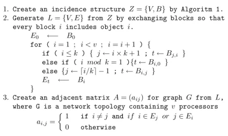
Algorithm 2for design of network configuration
1. Create an incidence structure Z={V, B} by Algoritm 1. 2. Generate L={V, E} from Z by exchanging blocks so that
every block i includes object i.
E0 ←− B0
for ( i= 1 ; i < v ; i=i+ 1 ) {
if ( i≤k ) { j←i×k+ 1 ; t←Bj,i }
else if ( i mod k= 1 ){t←Bi,0 } else {j← di/ke −1 ; t←Bi,j }
Et ←− Bi
}
3. Create an adjacent matrix A= (aij) for graph G from L,
where G is a network topology containing v processors ai,j=
1
if i6=j and if i∈Ej or j∈Ei
0 otherwise
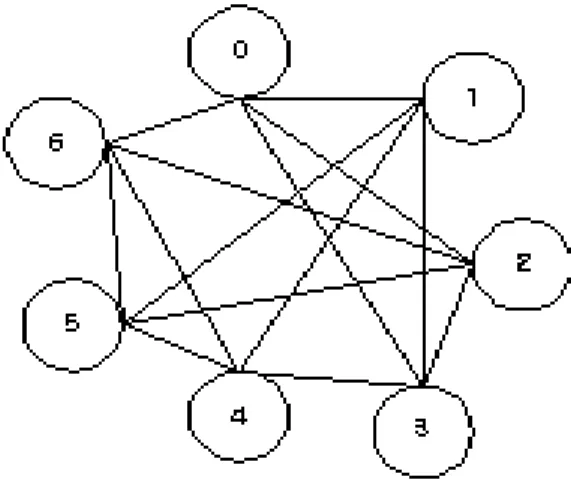
Ghasv nodes sinceGis created from (v, k+ 1,1)-configuration. Each block L[i] is composed ofk+ 1 elements andi is the one of them. Each node obtains 2klinks from Step 3 of Algorithm 2. So, G become a 2k-regular graph. therefore there are (2k×v)/2 = vk links in G. Given Z = {V, B}described on Fig.1, performance of Algorithm 2 is shown on Table 2 and Fig.1.
TABLE 2 . Blocks ofLgenerated fromZ of Table 1 L E0 ={0, 1, 2} E1 ={1, 3, 5} E2 ={2, 3, 6} E3 ={0, 3, 4} E4 ={1, 4, 6} E5 ={2, 4, 5} E6 ={0, 5, 6}
4. Design of an Efficient Load Balancing Algorithm on (v,k+1,1)-configured networks
An efficient load balancing algorithm is now constructed on (v,k+1,1)-configured networks generated by Algorithm 2.
FIGURE 1 . (7,3,1)-configured network obtained fromL
Definition 2. Construct two sets Si and Ri consisting of adjacent k nodes,
whereSi is a set of nodes to which nodeisends workload information andRi is
a set of nodes to receivei’s workload information.
Si =v| v∈Ei−i}
Ri =v | ⊂∈Ev & i6=v}
Definition 3. Generate two setsSFiandRFi, whereSFi(j) is a set of workload
information for i’s adjacent nodes transmitted from node i to node j at time T2t and RFi(j) isi’s workload information transmitted from node i to node j
at timeT2t+1.
SFi={SFi(j)|j∈Si, SFi(j) ={Ei− {j}}.
RFi={RFi(j)|j∈Ri, RFi(j) =i}.
Algorithm 3for construction of an efficient load balancing algorithm
1. Node i sends a set of workload information SFi(j) to node
j∈Si at T2t and renews a table of workload information.
2. Node i sends a set of workload information RFi(j) to node
j∈Ri at T2t+1 and renews a table of workload information. 3. Repeat the first step.
The following table indicates that nodeisends workload information SFi(j)
and RFi(j) to nodej at times T2t and T2t+1, respectively. So every node can
obtain workload information for all the nodes atT2t+2and this fact is proven in Theorem 2.
Theorem 2. According to Algorithm 3, every node obtains workload informa-tion for all the nodes atT2t+2.
P roof. AtT2t, node isends workload information for SFi(j) to node j. On an
aritrary pair (SFi1(j),SFi2(j)), i16=i2, intersection of these sets is empty since
on (v,k+1,1)-configuration, every two objects appears simultaneously in exactly one of v blocks and nodej is an element of Si1 and Si2, respectively. So node
j obtains workload information for k2 nodes. And at T2
t+1, node i transmits
its workload information to node j by Algorithm 3-2. Then, node j receives k workload information. Therefore, node j receives workload information for k2+knodes at T2
t+2.
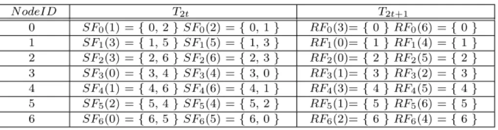
TABLE 3. Two steps for sending workload information from Node i
N odeID T2t T2t+1 0 SF0(1) ={0, 2}SF0(2) ={0, 1} RF0(3)={0}RF0(6) ={0} 1 SF1(3) ={1, 5}SF1(5) ={1, 3} RF1(0)={1}RF1(4) ={1} 2 SF2(3) ={2, 6}SF2(6) ={2, 3} RF2(0)={2}RF2(5) ={2} 3 SF3(0) ={3, 4}SF3(4) ={3, 0} RF3(1)={3}RF3(2) ={3} 4 SF4(1) ={4, 6}SF4(6) ={4, 1} RF4(3)={4}RF4(5) ={4} 5 SF5(2) ={5, 4}SF5(4) ={5, 2} RF5(1)={5}RF5(6) ={5} 6 SF6(0) ={6, 5}SF6(5) ={6, 0} RF6(2)={6}RF6(4) ={6} 5. Conclusion
In order for the system to increase utilization and to reduce response time, workload should be balanced. In this paper, we present an efficient load bal-ancing algorithm on (v, k+ 1,1)-configured networks consisting ofv nodes and vk links. Our algorithm needs only O(v√v) message overhead and each node receives workload information from all the nodes without redundancy and load balancing is maintained so that every link has same amount of traffic for trans-ferring workload information.
References
1. M. Willebeek-Lemair and A. P. Reeves,Strategies for dynamic load-balancing on highly parallel computers, IEEE Transactions on Parallel and Distributed Systems, vol. 4, no. 9, pp. 979-993, 1993.
2. B.A. Shirazi,Scheduling and load balancing in parallel and distributed systems, IEEE Com-puter Society Press, 1995.
3. S. Hosseini, B. Litow, M. Malkawi, Analysis of a graph coloring based distributed load balancing algorithm, Journal of Parallel and Distributed Computing, vol. 10, no. 2, pp. 160-166, 1990.
4. C.Hui, S.Chanson,Hydrodynamic Load Balancing, IEEE Transactions on Parallel and Dis-tributed System, vol. 10, no. 11, pp. 1118-1137, 1999.
5. K. Nam, J. Seo, Synchronous Load balancing in Hypercube Multicomputers with Faulty Nodes, Journal of Parallel and Distributed Computing, vol. 58, pp. 26-43, 1999.
6. H. Rim, J. Jang,Method for Maximal Utilization of Idle links for Fast Load Balancing, Journal of Korea Information Processing Society, vol. 28, no. 12, 2001.
7. S. Das, D. Harvey, and R. Biswas,Adaptive Load-Balancing Algorithms Using Symmetric Broadcast Networks, NASA Ames Research Center, TR NAS-97-014, May 1997.
8. S. Das, D. Harvey, and R. Biswas,Parallel Processing of Adaptive Meshes with Load Bal-ancing, IEEE Transactions on Parallel and Distributed Systems, vol. 12, no. 12, 2001. 9. C.L.Liu,Block Designs in Introduction to Combinatorial Mathematics, McGraw-Hill, pp.
359-383, 1968.
10. I. Chung, W. Choi, Y. Kim, M. Lee, The Design of conference key distribution system employing a symmetric balanced incomplete block design, Information Processing Letters, vol. 81, no. 6, pp. 313-318, 2002.3.
Ilyong Chungreceived the B.E. degree from Hanyang University, Seoul, Korea, in 1983 and the M.S. and Ph.D. degrees in Computer Science from City University of New York, New York, in 1987 and 1991, respectively. From 1991 to 1994, he was a senior technical staff of Electronics and Telecommunication Research Institute(ETRI), Daejon, Korea. Since 1994, he has been an Associate Professor in Department of Computer Science, Chosun Univeristy, Kwangju, Korea. His research interests are in computer networking, security systems and coding theory.
Department of Computer Engineering, Chosun University, Kwangju, Korea e-mail:[email protected]
Youngeun Baereceived the B.S. and M.S. degrees in computer science from Chosun Uni-versity, Kwangju, Korea in 1984 and 1986, respectively and Ph.D. degree from Wonkwang University, Korea in 2002. Since 1987, he has been an Associate Professor in Department of Computer Science, Chosun Univeristy, Kwangju, Korea. His research interests are in Parallel processing and security systems.
Department of Computer Engineering, Chosun University, Kwangju, Korea e-mail : [email protected]