Contents lists available atScienceDirect
Applied Energy
journal homepage:www.elsevier.com/locate/apenergy
Impacts of a medium voltage direct current link on the performance of
electrical distribution networks
☆
Qi Qi
a, Chao Long
a, Jianzhong Wu
a,⁎, James Yu
baInstitute of Energy, School of Engineering, CardiffUniversity, CardiffCF24 3AA, UK bSP Energy Networks, Blantyre, Scotland G72 0HT, UK
H I G H L I G H T S
•
Assessing impacts of an MVDC link on network performance with high DG penetrations.•
Investigating the capability of an MVDC link in increasing the DG hosting capacity.•
A real-time control method for MVDC link was proposed.•
Control strategies considering multiple operational objectives were developed. A R T I C L E I N F OKeywords:
Electrical distribution network
Medium Voltage Direct Current (MVDC) link Distributed generation
Control strategy
Multi-objective optimization
A B S T R A C T
With an increasing number of distributed generators (DGs) integrated into distribution networks, operational problems such as excessive power losses, voltage violations and thermal overloads have occurred. Medium Voltage Direct Current (MVDC) technology represents a candidate solution to address these problems as well as to unlock the capacity of existing electrical network assets. In this paper, the capability of using an MVDC link to improve the performance of a distribution network, i.e. reducing power losses and increasing the hosting ca-pacity for DG connections was investigated. A grid transformer (GT)-based control method was developed, in which the real-time data of the active powerflow at GTs was used to specify the set-points of an MVDC link. The control strategies considered multiple objectives, i.e. power loss reduction, feeder load balancing, voltage profile improvement, and trade-offoptions among them. The response curves of these control strategies were developed through offline studies, where a multi-objective Particle Swarm Optimization (MOPSO) method was used. Case studies on a real distribution network were conducted to analyze the impacts of the MVDC link. The perfor-mances of the network were evaluated and compared between the proposed control strategies, using real de-mand and generation profiles. Results revealed that, for an MV distribution network, it might be beneficial to switch between different control strategies with the variations in demand and generation conditions. Results also showed that, regardless of the control strategy used, the MVDC link can significantly increase the network hosting capacity (up to 15%) for DGs, and reduce about 50% of power losses compared to a conventional alternative current (AC) line for the test network.
1. Introduction
In recent years, an increasing number of distributed generators (DGs) have been integrated into electrical distribution networks[1,2], which pose challenges for Distribution Network Operators (DNOs), such as excessive power losses, voltage violations, and thermal overloads [3]. Solutions to address these issues whilst providing enhanced
capacity for distribution networks to host DGs are required.
With the rapid development of power electronic technologies, and their applications to High Voltage (HV) transmission networks and Low Voltage (LV) distribution networks, analogies are being made with the use of direct current (DC) in Medium Voltage (MV) networks[4]. DC and power electronic technologies provide controllability andflexibility to distribution networks, and can be used to increase the hosting
https://doi.org/10.1016/j.apenergy.2018.08.077
Received 5 February 2018; Received in revised form 14 August 2018; Accepted 15 August 2018
☆The short version of the paper was presented at ICAE2017, Aug 21-24, Cardiff, UK. This paper is a substantial extension of the short version of the conference paper.
⁎Corresponding author.
E-mail address:wuj5@cardiff.ac.uk(J. Wu).
0306-2619/ © 2018 The Authors. Published by Elsevier Ltd. This is an open access article under the CC BY license (http://creativecommons.org/licenses/BY/4.0/).
capacity for DGs of existing networks.
Research on distribution-level power electronic devices has been conducted. The use of shunt voltage source converters (VSCs) in rural networks for voltage regulation was carried out in[5]. In[6], an in-telligent node, which is implemented by several VSCs connected to a common DC-bus, was proposed to extend the current limits of feeders, as well as to improve the voltage profiles. In [7] distribution-level power electronic devices with different topologies were assessed and compared, considering their capabilities in relieving network con-straints and accommodating DGs. More recently, the capability of back-to-back VSCs based Soft Open Point (SOP) to regulate voltage and therefore to increase DG penetration was quantified in[8]. The benefits of using SOPs in a distribution network were analyzed in[9]. A sensi-tivity method to define the optimal operating region of SOP was pro-posed in[10]. A few initiative pilot projects have been trialed using SOPs in MV and LV distribution networks in the UK, such as‘Network Equilibrium’ [11] and ‘Flexible Urban Networks Low Voltage’ [12] projects.
The above studies assessed the impacts of power electronic devices on the performances of distribution networks, and the topologies were mainly back-to-back VSCs. The benefit of deploying a point-to-point application of VSCs, e.g. an MVDC link, rather than a back-to-back application is that it enablesflexible power and voltage control over a wider area. Recent studies on MVDC links have been conducted from different perspectives. In[13], the utilization of DC links to enhance the integration of DGs, and to reduce power losses in distribution systems was investigated, where the DC link control set-points were determined by the optimal powerflow. The benefits of incorporating DC links to radial distribution networks were assessed in[14], where the maximum load or DG that can be served by the network were determined. The benefits of using multi-terminal DC links to reduce power losses and improve voltage profiles, as well as to mitigate transient power quality perturbations were analyzed in[15]. A cost-benefit evaluation of using DC links as interconnectors in dense-load urban networks was carried out in[16]. The capabilities of using MVDC links to increase network hosting capacity for DG connections were investigated in[17,18], and different levels of communication functionalities were considered in [18]. These studies have mainly focused on the evaluation of benefits of DC links in reducing power losses, increasing system loadability or in-tegrating more DGs, whereby centralized control schemes are required. However, the centralized control schemes rely on measurement and communication infrastructures which might be subjected to malfunc-tions or failure. To account for this, operational strategies to keep DC links connected in a safe manner in the case of a communication failure were proposed in[19].
Due to the limited number of available real-time measurements in distribution networks and the intermittence of demand and distributed generation, distributed control strategies requiring fewer measurements are more viable than the centralized ones. In addition, the cost of as-sociated ICT (information and communication technology)
infrastructures required for centralized control accounts for a large portion of the total costs [20], which makes centralized control less attractive. A real-time control strategy of an MVDC link which uses only the measurements at grid transformers was investigated in [21]. However, the MVDC link set-points were obtained by using sensitivity analysis, in which a range of active power values were examined with the one inducing lowest network power loss selected as the MVDC link set-point. The drawback of using sensitivity analysis is that only limited number of candidate values, rather than the entire solution space are considered. This might result in underutilization of MVDC links. Therefore, effective control strategies for MVDC link need to be in-vestigated. Also, as the performances of an MVDC link depend on the control strategies applied, different control strategies for an MVDC link need to be assessed and compared.
In this paper, a real-time control method for an MVDC link was proposed, in which the active powerflowing through the grid trans-formers (GTs) is used to determine the set-points of an MVDC link. GTs are the transformers that supply power to the network. This method is called GT-based control. The GT-based control requires only measure-ments at the GTs rather than the load and generation data at each load point (i.e. substations) of the network. This work considered control strategies with multiple objectives, i.e. power loss reduction (PLR), feeder load balancing (FLB), voltage profile improvement (VPI), and compromise strategies providing trade-offs among them. The response curves of these control strategies were developed through offline stu-dies, where a multi-objective Particle Swarm Optimization (MOPSO) method was used. Assessments and comparisons between different control strategies were carried out. To evaluate the effectiveness of implementing MVDC link with the GT-based control method, case studies on a real distribution network were conducted.
This work has the following contributions: (1) proposing a novel real-time control method for MVDC link, namely the GT-based control method, which only requires communication links between the grid transformers and the controller of the MVDC link; (2) control strategies considering multiple objectives were developed and the network per-formance of these control strategies were compared; and (3) impacts of an MVDC link on the performances of distribution networks in terms of the capability of reducing losses and increasing the network’s DG hosting capacity were investigated.
2. MVDC link in distribution networks
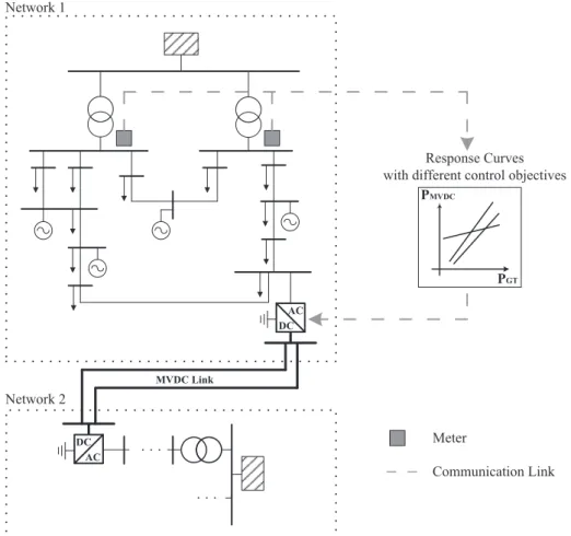
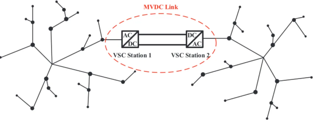
Fig. 1shows a schematic diagram of an MVDC link connecting two distribution networks. The MVDC link is constructed via fully con-trollable power electronic converters. A voltage source converter (VSC) station is used for the conversion between AC and DC at each terminal of the MVDC link. The MVDC link allows for real power exchange be-tween the two terminals as well as reactive power supports at both sides. The VSC can perform as the control of: (a) DC voltageVdc; (b) active powerP; (c) AC voltageVac; (d) reactive powerQ and (e) AC
VSC Station 1 DCC AC A ACC DC D VSC Station 1 MVDC Link VSC Station 2
frequency f. Typical control modes of an MVDC link under normal network operating conditions are listed in Table 1, where one VSC station controls the active power flowing through the link, and the other VSC station is used to maintain the DC voltage. In addition, for each VSC station either the reactive power or the AC side voltage can be controlled.
3. Modelling of MVDC link
In this paper,PVac−V Vdc ac was selected as the control mode of the MVDC link, and the reactive power outputs were adjusted in real time to maintain the voltage at specified value, e.g. 1 p.u. It is considered that fewer converters with higher power ratings are preferred than more converters with lower ratings of each. Since higher power rating VSC has the merits of higher efficiency, lower power losses and fewer peripheral devices associated, such asfilters and line reactors. In ad-dition, the footprint of the VSC station can be reduced with fewer VSCs [22]. For simplicity, the term VSC is used to denote VSC station in this paper.
To fully evaluate the effects of an MVDC link on network operations, a mathematic power injection model of MVDC link was developed by considering the following modelling constraints.
•
Active power constraints:+ + − =
PVSC1 PVSC2 PDC loss 0 (1)
wherePVSC1,PVSC2are the active powerflow through each VSC.PDC loss− is the loss within an MVDC link, which is relatively low (approximate 1–2% of the active powerflowing through the MVDC link[23]) com-pared to the total losses within the network and thus can be neglected. Therefore, Eq.(1)can be simplified as:
= −
PVSC1 PVSC2 (2)
•
Reactive power constraints:⩽ ⩽ =
QVSC nmin, QVSC n, QVSC nmax, (n 1, 2) (3) whereQVSC n, is the reactive power at thenthterminal of the MVDC link. QVSC nmin, andQVSC nmax, are the lower and upper limits of reactive power provided by the VSC at terminaln.QVSC nmax, is positive indicates that re-active power is injected to the network, andQVSC nmin, is negative indicates that reactive power is absorbed from the network.
•
Capacity constraints:+ ⩽
PVSC n2 , QVSC n2 , SVSC n, (4)
whereSVSC n, is the rated capacity of the VSC at thenthterminal of the MVDC link.
The MVDC link is modelled using the above equations. Then, the active and reactive power outputs of the MVDC link can be integrated into load flow algorithm without considering detailed design of the converter controllers.
4. GT-based control method
Fig. 2 presents an overview of the proposed GT-based control method, where data from the GTs are provided to the controller of the MVDC link by a direct communication link [21]. Compared to the
centralized control schemes, which require observability of the entire network and heavily rely on the corresponding communication infra-structure[24], the GT-based control is relatively simpler with lower cost, making the control scheme an attractive interim option[25,26]. In Fig. 2, Network 1 has a large amount of DG connections, and therefore Network 1 is becoming problematic and even approaching its voltage and thermal limits. In this context, Network 1 is focused on.
For the real-time operation of the MVDC link, a response curve is needed. A response curve defines the linear relation between the active power set-point of the MVDC link (PMVDC), and the active powerflowing through the GTs (PGT). The idea of using the response curves is that, the most adequate active power provided by the MVDC link is related to the active powerflowing through the GTs. When the active power mea-sured at the GTs is positive, i.e. the demand in the network is greater than the DG output, active power is required to be imported to the network. In this case the active power provided to the network via the MVDC link would support the network’s electricity demand. When the active power measured at the GTs is negative, i.e. the DG output is greater than the demand, active power is required to be exported from the network. In this case, exporting active power via the MVDC link would support to consume the surplus generation in the network. The response curve is obtained by offline studies, where the historical net-work data is used.
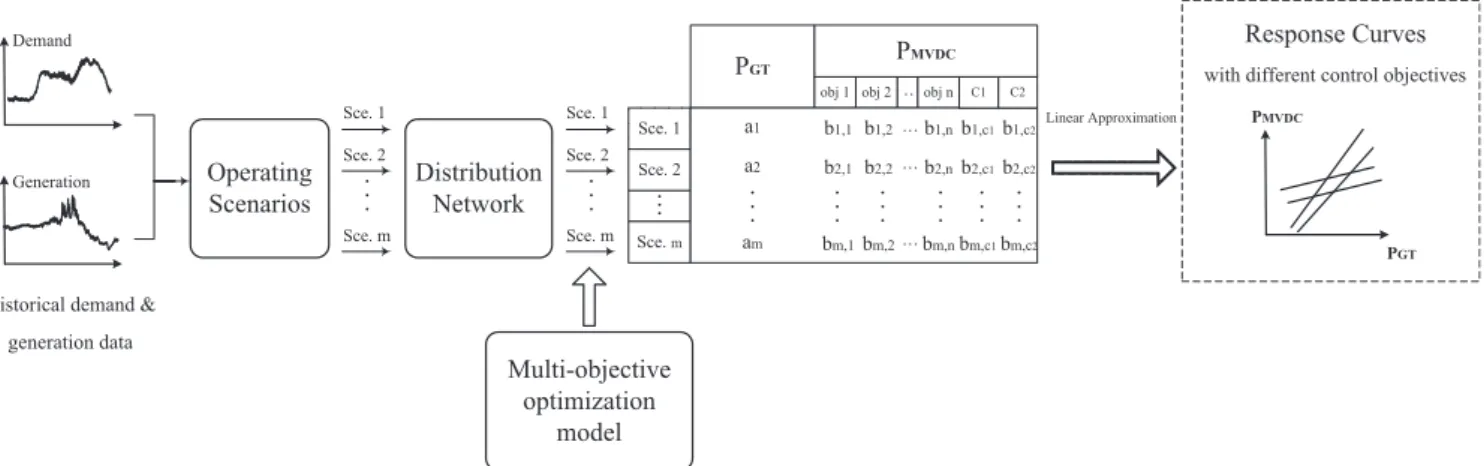
For the operation of an MVDC link, the network operators may have different focuses, e.g. losses reduction, or voltage improvement. In this study, different objectives were considered. These objectives result in different response curves, which provide the DNOs with more operation options. In the offline studies, a multi-objective Particle Swarm Optimization (MOPSO) method was used. The active powerflowing through the Grid Transformers (PGT), when the active power set-point of the MVDC link was zero, was also recorded. Then a linear approxima-tion of the optimal set-points PMVDC and the corresponding PGT was carried out to find their linear relations, which were the response curves. These curves were used in real-time to specify the set-points of the MVDC link.
4.1. Problem formulation
The determination of response curves with different objectives was formulated as a multi-objective optimization problem. Three opera-tional goals were considered and formulated as:
Minimize f[ ,1 f2,f3] (5)
where f1 is the objective function for Power Loss Reduction (PLR), where active power losses in feeder lines and transformers of a network were considered:
∑
= = × = f PLR I r k N k k 1 1 2 branch (6) In Eq.(6),Ikis the currentflowing through branchk.rkis the resistance of that branch, andNbranch is the total number of branches including lines and transformers.f2 is the objective function for Feeder Load Balancing (FLB). The balance of loads within a network can be achieved by minimizing the line utilization index:
= = ∑= f FLB N ( ) j N S S line 2 1 2 line j j rated, (7) In Eq.(7),Sjis the apparent powerflow in linej, andSj rated, is the rated capacity of the line.Nlineis the total number of feeder lines. Theline utilization indexreflects the average degree of utilization of all feeder lines in a network.
f3is the objective function for Voltage Profile Improvement (VPI). The improvement of voltage profiles can be achieved by minimizing the
Table 1
Control modes of an MVDC link under normal operating conditions. Control Mode VSC Station 1 VSC Station 2
1 PQ PV/ ac V Q V Vdc /dc ac
voltage profile index: = = ∑= − f VPI V V N ( ) i N i i rated bus 3 1 , 2 bus (8) In Eq.(8),ViandVi rated, are the real and nominal voltage magnitudes at busi.Nbusis the total number of buses. Thevoltage profile indexreflects the average degree of dispersion of all bus voltages from the nominal value.
In addition to the constraints of an MVDC link as shown in Eqs. (2)–(4), the network active and reactive powerflows, and the voltage and thermal limits were also taken into consideration:
The power balance equations for a network are[27,28]:
= + Vi ei jfi (9)
∑
∑
= − + + = = Pical ei (G e B f) f (G f B e) j N ij j ij j i j N ij j ij j 1 1 bus bus (10)∑
∑
= − − + = = Qical fi (G e B f) e (G f B e) j N ij j ij j i j N ij j ij j 1 1 bus bus (11) whereVi is the voltage at busi, andeiandfiare its real and imaginary components.PicalandQicalare the calculated active and reactive power injections at busi.GijandBijare the conductance and susceptance of the branch connecting busesiandj.
In the Newton Raphson method, Eqs.(10) and (11)can be expanded into Taylor series and the followingfirst order approximation can be obtained[28]: ⎡ ⎣ ⎢ ⎤⎦⎥= ⎡⎣ ⎤⎦ P Q J V θ Δ Δ Δ Δ it it it it (12) = ⎡ ⎣ ⎢ ⎢ ⎤ ⎦ ⎥ ⎥ ∂ ∂ ∂ ∂ ∂ ∂ ∂ ∂ J P V P θ Q V Q θ cal cal cal cal (13) whereJis the Jacobian matrix whose elements are listed in[29]. The Jacobian matrix is evaluated atV=Vit andθ=θit.V andθ are the voltage magnitude and phase angle.itis the iteration count.
= +− V V V Δ it it 1 it (14) = +− θ θ θ Δ it it 1 it (15) = − P P P Δ it sp cal it. (16) = − Q Q Q Δ it sp cal it. (17)
wherePspandQsp are the specified net active and reactive power in-jections. Pcal it, andQcal it, are the calculated net active and reactive power injections at iterationitusingVitandθit.
The voltage and thermal limits are expressed in Eqs.(18) and (19):
⩽ ⩽
Vimin | |Vi Vimax (18)
whereViminandVimaxare the lower and upper voltage limits at busi.
⩽ ∈ …
S S k N
| k| kmax {1, 2, , branch} (19)
whereSkandSkmaxare the actual and upper limit of the apparent power flow of branchk.
4.2. Solution methodology 4.2.1. Pareto-dominance principle
It is common that multiple objectives are incommensurable in nature and can be conflicting with each other, aggregating multiple objectives into one equation may result in losing significance.
Pareto-Response Curves
with different control objectives
Network 1
Network 2
AC DC DC ACP
GTP
MVDCMeter
Communication Link
MVDC Linkdominance principle[30], on the contrary, is based on a simultaneous optimization along different objective functions. It provides a range of alternative solutions rather than a single one, leading to moreflexibility in the process of decision making and operation of the network. In this study, Pareto-dominance principle was adopted to solve the multi-ob-jective optimization problem.
Assuming a number ofNobj functions are to be minimized, solution ‘A’is said to dominate solution‘B’if:
∀n∈[1, 2, …,Nobj]: f An( )⩽f Bn( )∩ ∃n∈[1, 2, …,Nobj]: f An( )<fn (20) where f An( )and f Bn( ) are the values obtained by solution A and B respectively along thenthobjective function.
Under this concept, a set of non-dominated solutions that are of equal interests amongst different objectives can be obtained. This set is called Pareto optimal set, which provides alternative solutions bringing outflexibility on network operation. For instance, some solutions may lead to lower power losses while others cause the network loading more balanced. The representation of Pareto optimal set in the solution space is called Pareto frontier.
4.2.2. Multi-objective optimization method
An improved multi-objective Particle Swarm Optimization (MOPSO) method based on Pareto-dominance principle developed in the authors’previous work, was used in the offline studies to derive the response curves of an MVDC link. The main contents and key for-mulations of the method are presented in this section, and more de-tailed explanations can be found in reference [31]. A number of de-mand and generation scenarios werefirst generated from the historical data of a network. For each scenario (with defined demand and gen-eration levels), the proposed MOPSO method was applied tofind op-timal set-points in the offline studies. The active power set-point of an MVDC link (PMVDC) was taken as the decision variable. Independent variables included the demand and generation of the network, and the reactive power outputs at both terminals of the MVDC link, which were adjusted accordingly to maintain the terminal voltage at specified value, e.g. 1 p.u. The novelty of this method is integrating both global and local search techniques to search for optimality. The MOPSO al-gorithm is adopted to explore the solution space globally. A local search technique, namely the Taxi-cab method, is used for solution space ex-ploitation, which refines the quality of solutions searched by MOPSO in each iteration. The improved MOPSO method is an effective tool for solving multi-objective optimization problems by providing qualified and diversified solutions with enhanced search capability.
Particle Swarm Optimization (PSO)[32]is used for global search due to its easy implementation, effective memory use, and an efficient maintenance of the solution diversity. As a multi-point search algo-rithm, PSO can provide a set solutions in a single run[33]. The search starts with a population of random search points named particles. Each particle is encoded by a position vector (x) containing the decision variable information.xis updated with the particle’s velocity vector (v) successively. In each iteration,vis updated with two best values. The first one is the individual/personal best position (pbest) achieved by each particle itself. The other one is the global best position (gbest) obtained by any particle among the population, which is used as a guide leading the population towards optimum. Updating equations of theithparticle are formulated as:
= + − + −
+
viiter ωviiter c r p( best i x ) c r g( x )
iter iiter best i iter iiter 1 1 1 , 2 2 , (21) = + + +
xiiter 1 xiiter viiter 1 (22)
whereωis the inertia weight.c1andc2are the cognitive learning factor and the social learning factor respectively. r1andr2 are two random numbers∈[0, 1]used to keep away from entrapment in local optimum. MOPSO is a multi-objective version of PSO. In PSO, the selection of pbestandgbestrelies on thefitness value of particles, which is determined
by their resulted objective function value. However, in a multi-objec-tive problem, since the solutions now have multiplefitness criteria, the concept of Pareto dominance is introduced to evaluate theirfitness. Recalling the Pareto-dominance principle (Eq.(20)) and the objective functions considered in this study (Eqs.(6)–(8)), thefitness value of a particle’s positionuis better than positionw, ifudominatesw(denoted asu≺w): ≺ u w, if: ⩽ < ⎧ ⎨ ⎪ ⎪ ⎪ ⎪ ⎩ ⎪ ⎪ ⎪ ⎪ = = ∑ × = = = = = ∑ = ⎛ ⎝ ⎜ ⎞ ⎠ ⎟ ∑ = − f u f w for all n and f u f w for some n f
f PLR I r f FLB f VPI ( ) ( ) , ( ) ( ) n n n n n kNbranch k k j Nline Sj Sj rated Nline iNbus Vi Vi rated Nbus 1 1 2 2 1 , 2 3 1 ( , )2 (23) The selection of personal best position is straightforward: if the current position of theithparticlexiiterdominates its previous personal best positionp −
best i iter
,
1, the new personal best positionp best i iter
, is set toxiiter. If xiiterandpbest i−
iter ,
1non-dominate each other, p best i
iter
, is set to either of them by applying random sampling (equal probability). Otherwise,pbest iiter
, is the same asp − best i iter , 1.
Regarding the selection ofgbest, research work has been carried out using approaches that aggregate all the objectives into a single function [34,35], or approaches that assign the objectives in order of importance [36,37]. Then during each iteration, the particle’s position that has optimal value along the aggregated function or the most important function is selected to begbest. There are also approaches that select the guide based on the Pareto dominance[38,39]. In the proposed MOPSO, an archive is used to store non-dominated solutions, and is updated iteratively based on the Pareto-dominance principle. The archive is empty at the beginning of the search. Then the non-dominated solutions of each iteration are added to it, and any solutions in it which are dominated by the new solutions are deleted from the archive. Eq.(24) illustrates the rules of selecting the global best position (gbest) to update particles in each iteration.Ais the archive that stores non-dominated solutions, andais a solution inA. When updating the position of theith particle (xi),xiisfirst checked whether it is dominated by any solution in the archive. If so, assuming the set of solutions in the archive that dominatexiisAxi, and the leader of theithparticle is selected from this set with equal probability, i.e.|A |−
xi 1. If xi belongs to the archive, clearly no solution in the archive dominatesxi. Therefore, a solution from the archive is selected randomly with equal probability, i.e.| |A−1 to lead theithparticle.
= ⎧ ⎨ ⎩ ∈ ∈ ∈ − − g a A with probability A if x A a A with probability A otherwise
| | | | best i i x x , 1 1 i i (24)
In the proposed MOPSO method,ε-dominance method [40]was used to restrict the archive size while maintaining the diversity of non-dominated solutions in the archive. A mutation operation using Cauchy method[41]was also included to avoid premature convergences.
Despite the global exploring capability, evolutionary algorithms are comparatively inefficient in solution space exploitation[42]. To over-come this deficiency and to enhance the search capability of evolu-tionary algorithms, the appropriate integration of global and local search techniques, which maintains the balance between exploration and exploitation, appears to be an ideal solution. In this method, a local search technique, namely the Taxi-cab method, is integrated tofine tune the non-dominated solutions, overcoming the drawback of original MOPSO in local optima trapping. The Taxi-cab method does not require information of the derivatives of objective functions, in which the search is performed by moving the decision variable along standard base vectors. The Taxi-cab method is applied to the solutions in the archive at the end of each iteration. New solutions obtained by the
Taxi-cab method that are not dominated by any members in the archive are added into the archive, and any members in the archive which are dominated by the new solutions are deleted.
It is to be mentioned that, the proposed MOPSO was used tofind the optimal set-points of an MVDC link in offline studies. Other optimiza-tion algorithms can also be used for the same purpose, and the algo-rithms with better search capability were considered to obtain more appropriate response curves.
4.2.3. Selecting compromise solutions from Pareto optimal set
When solving real-word problems, a compromise solution may be required. Ideally, such solution belongs to the Pareto optimal set and takes into account the preferences of decision makers. In this study, two methods, namely the reference point approach [43]and the utopian point method[44]were used for selecting two compromise solutions, which are trade-offs among multiple criteria.
The reference point approach aims to reach a solution on the Pareto frontier that locates near to a specific reference point, which is normally pre-defined by decision makers. In this study, since the information from decision makers is unknown, a hypothetical point that with the minimum values of each objective function is considered as the re-ference point. The normalized Euclidian distance between each solution on the Pareto frontier and the reference point is calculated as:
∑
⎜ ⎟ = ⎛ ⎝ − − ⎞ ⎠ = d w f a R f f ( ) a n N n n n n max n min 1 2 obj (25) whereNobjrefers to the number of objective functions considered, and in this studyNobj=3.dais thefitness value of theath solution on the Pareto frontier defined by the reference point approach.fnmaxandfn min are the maximum and minimum values of thenth objective function obtained from the Pareto optimal set. f an( )is the value of theath so-lution along thenthobjective.Rnis thenthcomponent of the reference point.wnis the weighting factor of thenthobjective reflecting the re-lative importance of different objectives. For the identification of a compromise solution, the one with lower distance to the reference point and, simultaneously, with higher weighting factor, will be selected preferentially.
The utopian point methodfirst searches for the optimal value along each objective function. Then the intersection of these single-objective optimal values is defined as the utopian point, which is normally lo-cated outside of the actual solution space. The point on the Pareto frontier with the shortest distance to the utopian point is selected as the compromise solution:
∑
= − = Da n ( ( )f a U) N n n 1 2 obj (26) whereDais thefitness value of theathPareto optimal solution definedby the utopian point method, andUnis the value of the utopian point along thenthobjective function.
When applying the proposed MOPSO method to the network, the size of archive Awas set to 50, i.e. the maximum number of Pareto optimal solutions stored in the archive in each iteration was 50. At the end of the search process, the stored Pareto solutions in the archive were 50 or about 50, and they were used for the determination of the best compromise solutions. The number, diversity and distance to the ideal points of Pareto solutions all have impacts on the quality of the Pareto frontier. Hence, Pareto frontiers with higher diversity and quality were considered to provide better compromise solutions.
The compromise solutions obtained by using the reference point approach (C1) and the utopian point method (C2), together with the optimal solutions along each single objective, were used to derive dif-ferent response curves of an MVDC link.
4.3. Process of obtaining responsive curves
For the GT-based control, the active power provided by an MVDC link (PMVDC) is related to the active powerflowing through the grid transformers (PGT). In this study, their relationship was simplified to a linear relation, i.e.PMVDC=αPGT+β. From a number of offline studies using the historical data of the test network, such relationship was quantified.
A schematic diagram showing the process of obtaining the response curve is presented inFig. 3, and the process is illustrated as follows: (1) Historical data of both demand and generation of the network
under study are categorized into several levels. For instance, de-mand levels include summer minimum and maximum, winter minimum and maximum. Levels with scaled-up magnitude are used to reflect the forecasted demand and generation in the future. The combination of these demand and generation levels represents different scenarios of a network with different demand and gen-eration conditions.
(2) For each scenario, the active powerflowing through GTs isfirst obtained. This is carried out by considering the active power set-point of the MVDC link is zero (i.e. with no powerflowing through the MVDC link). Next, with the MVDC link in operation, the im-proved MOPSO method is applied to obtain the optimal set-points of the MVDC link in the offline studies. The optimal set-points when considering one objective are divided into one group. This means there would be 5 groups of optimal set-points (i.e. objectives for power loss reduction, feeder load balancing and voltage profile improvement, and two compromise solutions).
(3) Repeat the procedure (2) for all scenarios. As a result, for each scenario, the active power at GTs and a group of set-points of the MVDC link are obtained. A linear approximation of the GT active
Operating
Scenarios
Sce. 1P
GTP
MVDC Sce. m Sce. 2obj 1 obj 2 obj n a1 am a2 b1,1 b1,2 b1,n b2,1 b2,2 b2,n bm,1bm,2 bm,n
Distribution
Network
Multi-objective
optimization
model
Historical demand &generation data Demand Generation Sce. 1 Sce. 2 Sce. m Sce. 1 Sce. 2 Sce. m
Response Curves
with different control objectives Linear Approximation PGT PMVDC C1 C2 b1,c1b1,c2 b2,c1 bm,c1 b2,c2 bm,c2power and the corresponding MVDC set-points is then carried out to derive the response curve. This would result in 5 response curves for the 5 different objectives considered.
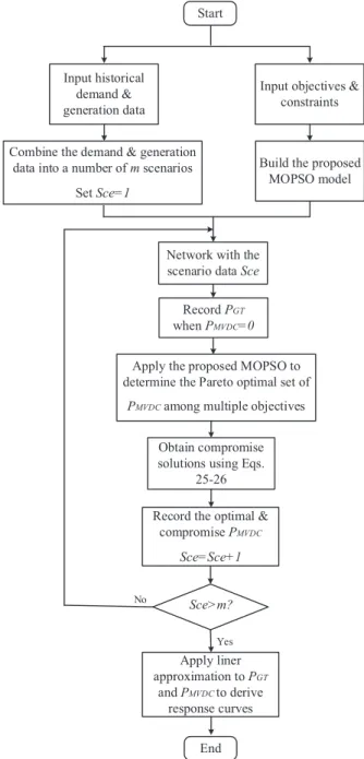
Aflowchart for the overall procedure of developing the GT-based response curves is illustrated inFig. 4.
5. Case studies
5.1. ANGLE-DC project and challenges on Anglesey network
As part of the Ofgem Electricity Network Innovation Competition (ENIC) award, ANGLE-DC [45]project aims to demonstrate a novel network reinforcement technique by converting an existing double 33 kV AC circuit into DC operation, i.e. an MVDC link, between the isle of Anglesey and North Wales.
Although there is no unified definition of DG penetration rate in the
literature, this paper followed the commonly used one, which is that DG penetration is the percentage of total capacity of DG units over the maximum loading capacity of a network. The same definition of DG penetration was used in[8,46].
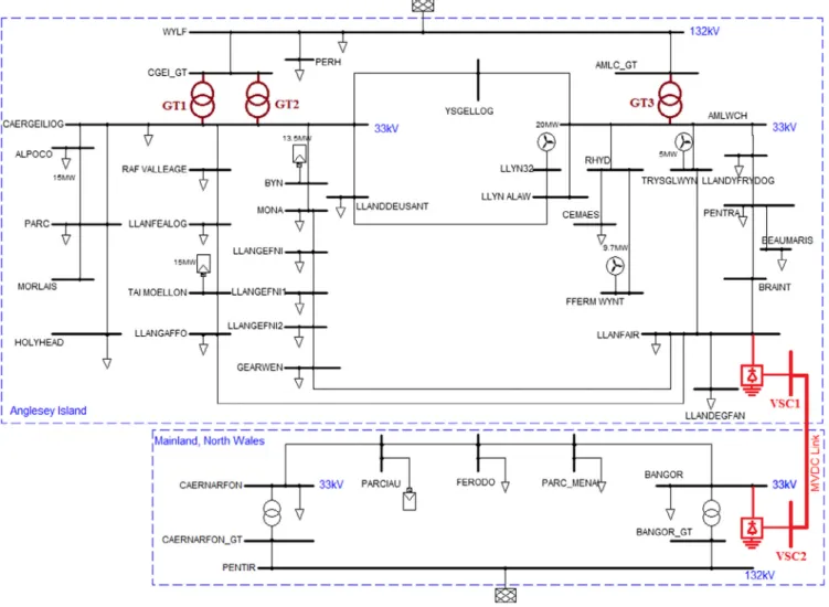
Fig. 5apresents a schematic of the 33 kV Anglesey network and a portion of the network on the mainland in North Wales. As shown in Fig. 5a, Bangor substation (mainland) and Llanfair PG substation (An-glesey) were selected to install VSC stations, and in between are the existing AC circuits that to be trailed to demonstrate the application of an MVDC link. A detailed single-line diagram is given inFig. 5b, where locations of the existing installation of DGs are shown. Details of the network data and the demand and generation data can be found through the link in the Acknowledgements. The meshed 33 kV Anglesey network is supplied by three 132/33 kV GTs at Amlwch and Caergei-liog. Currently the Anglesey network has a high penetration of DG and is sensitive to the configuration of the transmission network. There will also be a significant amount of additional demand on Anglesey due to planned regional redevelopment, and the peak load of Anglesey net-work is forecasted to be 81.82 MVA in 2023. Three wind farms with a total capacity of 34.7 MW, and two solar farms with a total capacity of 28.5 MW are already installed on Anglesey as shown inFig. 5. Three additional DGs, with a total capacity of 67.8 MW have been contracted and will be installed by 2023. Therefore, the total DG penetration rate of the Anglesey network is forecasted to reach 152% by 2023. The main challenge on Anglesey is that uncontrolled powerflows are predicted to exceed the thermal limits of cables and overhead lines. Managing the network within voltage and thermal limits is becoming problematic, due to the network topology, high levels of demand and DG penetra-tions. The adoption of MVDC link represents a solution to expand network operationalflexibility, and to provide extra capacity for the integration of renewable generations.
A model of real Anglesey network was built and analyzed in IPSA 2 software. The improved MOPSO method and the proposed GT-based control strategies were implemented with python scripting. In the si-mulation, the capacity of each VSC is rated at 30.5 MVA, with the active power ranging from−25 MW to 25 MW, and the reactive power ran-ging from −15 MVAr to 15 MVAr. The decision variables are con-tinuous values within these limits. The voltage limit is set to be ± 6% of the nominal voltage. The capacity limit of each branch is according to its real rating.
Start
Input historical demand & generation data Combine the demand & generation
data into a number of m scenarios
Set Sce=1
Network with the scenario data Sce
Record PGT
when PMVDC=0
Apply the proposed MOPSO to determine the Pareto optimal set of
PMVDC among multiple objectives
Record the optimal & compromise PMVDC Sce=Sce+1 Sce>m? Apply liner approximation to PGT and PMVDC to derive response curves End Yes No
Input objectives & constraints
Build the proposed MOPSO model
Obtain compromise solutions using Eqs.
25-26
Fig. 4.Flowchart for developing the GT-based response curves of an MVDC link.
5.2. GT-based control for the MVDC link
To derive response curves of the MVDC link, the procedure illu-strated in Section 4.3was applied. Firstly, active powerflows at the Anglesey GTs were calculated under different network operating sce-narios, while assuming no active power transfer was provided by the MVDC link. Historical and forecasted demand and generation data of Anglesey were used to form different scenarios. For the demand,five levels from 24.56 MVA to 81.82 MVA were taken into account, corre-sponding to: summer minimum (24.56 MVA); summer maximum (37.64 MVA); existing winter maximum (74.70 MVA); existing winter maximum uniformly increased by 5%, denoting the forecasted winter maximum in 2019 (77.94 MVA); and existing winter maximum uni-formly increased by 11%, denoting the forecasted winter maximum in 2023 (81.82 MVA). For the generation,five levels between 0 MW and maximum capacity of 125 MW were considered, which included both connected and contracted DGs on Anglesey.
Table 2shows the active powerflows (in MW) at the GTs. A positive sign means the power is imported from the upstream transmission system to Anglesey, and a negative sign means a reverse power flow from Anglesey to the transmission system.
For each scenario, the MVDC link was in operation with its set-points calculated by using the improved MOPSO method. Two com-promise set-points were also obtained by applying the reference point approach, and the utopian point method to the Pareto frontier of each scenario.
Fig. 6shows the response curves of the MVDC link with different control objectives, where the active power flowing through GTs
(Table 2) and the corresponding set-points of the MVDC link were firstly plotted by many dots (i.e. marked by circles, crosses, triangles, rhombuses, and squares to differentiate the control strategies). The circles correspond to the MVDC link set-points when considering power loss reduction (PLR) as the objective. The crosses represent the set-points when considering feeder load balancing (FLB) as the objective. The triangles are the set-points when improving the voltage profiles (VPI) was considered as the objective. The rhombuses are the com-promise set-points (C1) obtained by using the reference point approach, and the squares are the compromise set-points (C2) obtained by using the utopian point method. Thesefive sets of dots were then used to derivefive straight lines by applying the least squares method, and the parameters of each line are listed inTable 3. These straight lines are the most appropriate operational curves for the active power set-points of
Fig. 5b.Single-line diagram of the 33 kV Anglesey network.
Table 2
MWflows through GTs on Anglesey under 25 scenarios of demand and gen-eration.
PGT(MW)
DEMAND (MVA)
SMIN SMAX WMAX WMAX_2019 WMAX_2023 24.56 37.64 74.70 77.94 81.82 DG (MW) 0 23.45 36.06 75.08 78.47 82.58 31.25 −8.04 4.45 43.12 46.48 50.51 62.50 −39.08 −26.69 11.61 14.94 18.89 93.75 −69.66 −57.39 −19.42 −16.13 −12.20 125 −99.69 −87.55 −49.94 −46.67 −42.80
the MVDC link.
It can be seen fromFig. 6andTable 3that, different control para-meters result in different slopes and intercepts on axes of the response curves, which lead to distinct performances of the MVDC link. How-ever, the trends of these response curves are similar.
5.3. Daily operation of different cases
5.3.1. Case 1: Daily network operation with the MVDC link using different control strategies
The GT-based control strategies use the measurements at GTs to provide the active power set-points of the MVDC link, while the oper-ating condition of the wide area of the network is unknown to the MVDC link. Therefore, it is essential to assess the real-time performance of the network.
One-day demand and generation profiles of Anglesey obtained from measurements on the real network are shown in Fig. 7. Taking half-hourly time steps, power losses of the Anglesey network with the MVDC link using different control strategies are shown inFig. 8. The power losses of the network when the link is operated in AC are used as a reference case. The daily average power losses and energy losses when using different strategies are listed inTable 4. It can be seen inFig. 8 andTable 4that, with the MVDC link, regardless the control strategy used, power losses of the network were reduced significantly compared to those when the link is operated in AC. Comparisons between control strategies showed that, the one for voltage profile improvement led to higher power losses than other strategies. This is due to the extra power injections from the MVDC link for voltage regulation. Power losses obtained with the strategy for power loss reduction remained the lowest over the day, and losses obtained with the strategy for feeder load balancing were the second lowest. The two compromise control
strategies achieved medium performances among these objectives. 5.3.2. Case 2: Daily network operation with modified demand and generation profiles
To consider the impact of high DG penetrations, the demand profile in Fig. 7was scaled down to the summer minimum, while the gen-eration was scaled up by multiplying the normalized daily profile of each DG. This case is recognized as the worst-case scenario[47,48]and provides the most vulnerable network operating condition. The mod-ified daily profiles are shown inFig. 9, and the half-hourly power loss over a day under the worst-case scenario is shown in Fig. 10. The corresponding average power losses and energy losses when using dif-ferent strategies are listed inTable 5.
Comparing the results inFigs. 8and10, it can be found that the control strategy leading to minimum power loss over a day was not the one for power loss reduction at all times. When the outputs from DGs were much greater than the demand (e.g. during the hours 13:00–16:00), the control strategy for feeder load balancing resulted in lower power losses than others. However, when the demand were greater than the generation (e.g. from 17:00 to 24:00), the control strategy for power loss reduction became the one with lowest losses again. Results indicated that there was no particular control strategy bringing minimum power losses to the network at all times. However, switching between different strategies as the net power demand within the network varied would be necessary. The results of switching be-tween strategies that incurred lowest power loss inFig. 10are shown in the last row ofTable 5.
5.4. Impacts of DG penetration
In the simulations the worst-case scenario was applied, in which Anglesey network was at its minimum demand. The maximum allow-able DG penetration reflects the maximum capacity of DG units the network can accommodate before any violation occurs, i.e. the DG hosting capacity. DG penetration was increased from 0 with an incre-ment of 5%. Three network performance metrics: daily energy loss; the maximum line utilization over a day; and the maximum bus voltage over a day were evaluated.
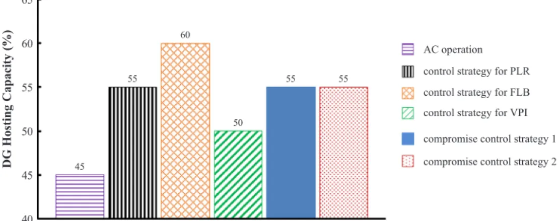
Firstly, the DG hosing capacity of the network was investigated with results shown inFig. 11.
FromFig. 11, it can be seen that MVDC link has the capability to increase the DG hosting capacity over the AC operation. The control strategy for feeder load balancing achieved the highest DG hosting Net power flow through GTs (MW)
MVDC link set-point (MW) -20 -15 -10 -5 0 5 10 15 20 25 -120 -100 -80 -60 -40 -20 0 20 40 60 80 100
Power Loss Reduction
Response Curves for:
Feeder Load Balancing Voltage Profile Improvement Compromise 1
Compromise 2
Fig. 6.Response curves of the MVDC link in Anglesey network with different control objectives.
Table 3
Control parameters of different response curves.
Response curves PMVDC=αPGT+β
α β
Power loss reduction 0.1225 8.91 Feeder load balancing 0.1216 10.16 Voltage profile improvement 0.2833 12.69
Compromise 1 0.1582 11.45
capacity, followed by the control strategy for power loss reduction, and the two compromise control strategies. With the MVDC link, an in-crease of DG hosting capacity up to 15% can be achieved in the An-glesey network.
Impacts of DG penetrations on the network performance metrics were also investigated. Results are shown inFigs. 12a–12c. It can be seen that, the degree of improvements along the performance metrics is different, depending upon the control strategy used. The maximum allowable DG penetration is also different among control strategies. With the control strategy for voltage profile improvement, a maximum DG penetration of 50% can be obtained, followed by the AC operation, of which the maximum DG penetration was 45%. The control strategy for feeder load balancing achieved the highest DG penetration of 60%. These results are consistent with the results shown inFig. 11.
It can be seen inFig. 12athat, with the MVDC link, daily energy lossesfirst decreased slightly as the DG penetration increased from 0 to 10%. Then as the DG penetration further increased, energy losses started to increase due to the large amount of reverse powerflows. The control strategy for power loss reduction led to minimum daily energy losses under all DG penetrations from 0 to 55%.Fig. 12bshows that, as DG penetrations increased, the line utilizationfirst decreased due to the offset of demand and generation. Then line utilizations became satu-rated gradually due to large amounts of reverse powerflows brought by
DG outputs. The control strategy for feeder load balancing led to the lowest line utilization under all DG penetrations. Although the control strategy for voltage profile improvement led to higher energy losses and line utilizations under all DG penetrations, it outperformed in miti-gating the voltage rise issue as shown inFig. 12c. Such control strategy can be used when voltage issues are the major concern of a network. It is also shown that, although not outperforming along any single op-erational metric, the compromise control strategies can always achieve medium performances along different criteria and relatively high DG penetrations. Such control strategies can be used as trade-offsolutions for the MVDC link operation.
0 5 10 15 20 25 30 35 40 1 2 3 4 5 6 7 8 9 10 11 12 13 14 15 16 17 18 19 20 21 22 23 24
P (
M
W
)
Time (half-hourly)
Demand GenerationFig. 7.Case 1: daily profiles of total demand and generation on Anglesey.
0.2 0.4 0.6 0.8 1 1.2 1.4 1.6 1.8 1 2 3 4 5 6 7 8 9 10 11 12 13 14 15 16 17 18 19 20 21 22 23 24
control strategy for PLR control strategy for FLB control strategy for VPI AC operation
compromise control strategy 1 compromise control strategy 2
Time (half-hourly)
Power
Loss
(MW)
Fig. 8.Power losses over a day of the network by using MVDC link and the original AC operation.
Table 4
Power and energy losses by using different control strategies as shown inFig. 8. Daily average power loss
(MW)
Daily energy loss (MWh) AC operation 1.556 37.35 Control strategy for PLR 0.562 13.49 Control strategy for FLB 0.578 13.87 Control strategy for VPI 0.673 16.15 Compromise control strategy 1 0.607 14.58 Compromise control strategy 2 0.613 14.72
6. Discussions
The GT-based control significantly reduces the costs associated with communication and measurement, compared to centralized control schemes, because the GT-based control only requires a few measure-ment points in a network (i.e. at the grid transformers). The exact costs and savings were not considered, since the scope of this work is to propose an effective control method of MVDC link and assess its ben-efits in increasing the network’s hosting capacity for DG connections, and in reducing the network losses. A cost/benefit analysis of con-structing an MVDC link in Anglesey network was carried out by SP Energy Networks in[49], but it is out of the scope of this work.
The ANGLE-DC project aims to convert an existing AC circuit into
DC operation, in order to enable improved power flow and voltage control while enhancing the thermal capability of the circuit in a timely manner. A point-to-point MVDC link was considered in this paper and it is consistent with the project. However, the proposed GT-based control method is applicable to other converter topologies as well, i.e. either a back-to-back, a multi-terminal, or a series connected MVDC link.
There are also limitations of the work. Since historical demand and generation data of a network are required in the offline studies to derive control curves of an MVDC link, the historical data would affect the performances of the control curves. In addition, when the network configuration is changed, the control curves may not be applicable to the new configuration and new offline studies need to be carried out.
Future works can be carried out with a modified network based on the real network data of Anglesey (e.g. modified network topology and/ or DGs in modified locations) to expand the learning of this study. Future works also include analyzing the impact of a multi-terminal MVDC link on distribution networks, and to compare a multi-terminal MVDC link with the two-terminal one. Using different optimization algorithms in offline studies to obtain the response curves of an MVDC link, and comparing their performances are also considered as one of the future works to be undertaken.
7. Conclusions
In this paper, impacts of an MVDC link on the performances of an electrical distribution network with high DG penetrations were in-vestigated. A real-time control method for MVDC link was proposed, in 0 10 20 30 40 50 60 70 1 2 3 4 5 6 7 8 9 10 11 12 13 14 15 16 17 18 19 20 21 22 23 24
P (
M
W
)
Time (half-hourly)
Demand GenerationFig. 9.Case 2: modified daily profiles of total demand and generation on Anglesey representing the worst-case scenario.
0.3 0.5 0.7 0.9 1.1 1.3 1.5 1.7 1.9 2.1 2.3 2.5 2.7 1 2 3 4 5 6 7 8 9 10 11 12 13 14 15 16 17 18 19 20 21 22 23 24 Time (half-hourly) Power Loss (MW)
control strategy for PLR control strategy for FLB control strategy for VPI AC operation
compromise control strategy 1 compromise control strategy 2
Fig. 10.Power losses over a day of the network by using MVDC link and the original AC operation (worst-case scenario).
Table 5
Power and energy losses by using different control strategies as shown in Fig. 10.
Daily average power loss (MW)
Daily energy loss (MWh)
AC operation 1.875 45.01
Control strategy for PLR 0.810 19.44 Control strategy for FLB 0.831 19.95 Control strategy for VPI 0.887 21.28 Compromise control strategy 1 0.865 20.77 Compromise control strategy 2 0.867 20.82 Switching to the strategy incurring
lowest power loss accordingly
45 55 60 50 55 55 40 45 50 55 60 65
control strategy for PLR control strategy for FLB control strategy for VPI AC operation
compromise control strategy 1 compromise control strategy 2
DG
Hosting
Capacity
(%)
Fig. 11.DG hosting capacity of the network by using MVDC link and the original AC operation.
0 5 10 15 20 25 30 35 40 45 50 0 5 10 15 20 25 30 35 40 45 50 55 60 Daily Energy Losses (MWh) DG penetration (%)
control strategy for PLR control strategy for FLB control strategy for VPI AC operation
compromise control strategy 1 compromise control strategy 2
Fig. 12a.Impacts of DG penetration on daily energy losses.
40 50 60 70 80 90 100 0 5 10 15 20 25 30 35 40 45 50 55 60 DG penetration (%) Daily Maximum Line Utilization (%)
control strategy for PLR control strategy for FLB control strategy for VPI AC operation
compromise control strategy 1 compromise control strategy 2
Fig. 12b.Impacts of DG penetration on daily maximum line utilizations.
DG penetration (%) Daily Maximum Bus Voltage (kV) 33.4 33.6 33.8 34 34.2 34.4 34.6 34.8 35 0 5 10 15 20 25 30 35 40 45 50 55 60
control strategy for PLR control strategy for FLB control strategy for VPI AC operation
compromise control strategy 1 compromise control strategy 2
which active power flows at the grid transformers were used to de-termine the set-points of the MVDC link. Control strategies considered multiple objectives, i.e. power loss reduction, feeder load balancing, voltage profile improvement, and compromise options among these criteria. These control strategies were developed through offline stu-dies, where an improved MOPSO method was applied. The effectiveness of implementing an MVDC link with the proposed control method was validated on a real network. Results indicated that, for an MV dis-tribution network, it might be beneficial to switch among different control strategies. Results also showed that, regardless of the control strategy used, an MVDC link significantly increases the network hosting capacity for DGs compared to the AC operation. For the distribution network under study, the MVDC link could bring up to 15% increase in DG hosting capacity over AC operation. The control strategy for feeder load balancing resulted in the highest DG hosting capacity, due to that the main challenges brought by the DGs are thermal overloading. Acknowledgments
This work has been partially supported by Ofgem Electricity Network Innovation Competition project ANGLE-DC 2016-2020 and FLEXIS (Flexible Integrated Energy Systems). FLEXIS is part-funded by the European Regional Development Fund (ERDF), through the Welsh Government. This work has also been partially supported by JUICE project,‘Joint UK-India Clean Energy Centre’(EP/P003605/1).
Information on the data supporting the results presented here, in-cluding how to access them, can be found in the CardiffUniversity data catalogue athttp://doi.org/10.17035/d.2018.0050208156.
References
[1] Wang Q, Zhang C, Ding Y, Xydis G, Wang J, Østergaard J. Review of real-time electricity markets for integrating distributed energy resources and demand re-sponse. Appl Energy 2015;138:695–706.
[2] Anaya KL, Pollitt MG. Options for allocating and releasing distribution system ca-pacity: deciding between interruptible connections andfirm DG connections. Appl Energy 2015;144:96–105.
[3] Esmaili M, Firozjaee EC, Shayanfar HA. Optimal placement of distributed genera-tions considering voltage stability and power losses with observing voltage-related constraints. Appl Energy 2014;113:1252–60.
[4] Mallwitz R, Engel B. Solar power inverters. Presented at the integrated power electronics systems (CIPS), 2010 6th international conference, Nuremberg, Germany; 2010.
[5] Ramsay SM, Cronin PE, Nelson RJ, Bian J, Menendez FE. Using distribution static compensators (D-STATCOMs) to extend the capability of voltage-limited distribu-tion feeders. Presented at rural electric power conference, Fort Worth, TX, USA; 1996.
[6] GraaffRAAd, Myrzik JMA, Kling WL, Enslin JHR. Intelligent nodes in distribution systems - optimizing steady state settings. Presented at IEEE power tech, Lausanne, Switzerland; 2007.
[7] Bloemink JM, Green TC. Benefits of distribution-level power electronics for sup-porting distributed generation growth. IEEE Trans Power Deliv 2013;28:911–9. [8] Bloemink JM, Green TC. Increasing distributed generation penetration using soft
normally-open points. Presented at the power and energy society general meeting, Providence, RI, USA; 2010.
[9] Cao W, Wu J, Jenkins N, Wang C, Green TC. Benefits analysis of soft open points for electrical distribution network operation. Appl Energy 2016;165:36–47. [10] Long C, Wu J, Thomas L, Jenkins N. Optimal operation of soft open points in
medium voltage electrical distribution networks with distributed generation. Appl Energy 2016;184:427–37.
[11] Western Power Distribution. Network equilibrium. Available: <https://www. westernpower.co.uk/Innovation/Projects/Current-Projects/Network-Equilibrium. aspx> [accessed Feb 2018].
[12] UK Power Networks. Flexible urban networks low voltage. Available: <http:// innovation.ukpowernetworks.co.uk/innovation/en/Projects/tier-2-projects/ Flexible-Urban-Networks-Low-Voltage/> [accessed Feb 2018].
[13] Marano-Marcolini A, Romero-Ramos E, Gomez-Exposito A, Maza-Ortega JM, Martinez-Ramos JL. Enhancing the integration of renewable sources in distribution systems using DC-links. Presented at the sustainable alternative energy, Valencia, Spain; 2009.
[14] Romero-Ramos E, Gomez-Exposito A, Marano-Marcolini A, Maza-Ortega JM, Martinez-Ramos Jl. Assessing the loadability of active distribution networks in the presence of DC controllable links. IET Gener Transm Distrib 2011;vol:5.
[15] Barragan M, Mauricio JM, Marano A, Nieves M, Churio J, Maza-Ortega JM, et al. Operational benefits of multiterminal DC-links in active distribution networks. Presented at the power and energy society general meeting, 2012 IEEE, San Diego, CA, USA; 2012.
[16] Sciano D, Raza A, Salcedo R, Diaz-Aguilo M, Uosef RE, Czarkowski D, et al. Evaluation of DC links on dense-load urban distribution networks. IEEE Trans Power Deliv 2016;31:1317–26.
[17] Qi Q, Long C, Wu J, Smith K, Moon A, Yu J. Using an MVDC link to increase DG hosting capacity of a distribution network. Presented at the 9th international con-ference on applied energy (ICAE), Cardiff, UK; 2017.
[18] Long C, Wu J, Smith K, Moon A, Bryans R, Yu J. MVDC Link in a 33kV distribution network. Presented at the 24th international conference on electricity distribution CIRED, Glasgow, UK; 2017.
[19] Marano-Marcolini A, Villarejo MB, Fragkioudaki A, Maza-Ortega JM, Ramos ER, Jaén AV, et al. DC link operation in smart distribution systems with communication interruptions. IEEE Trans Smart Grid 2016;7:2962–70.
[20] Weckx S, Gonzalez C, Rybel TD, Driesen J. LS-SVM-based on-load tap changer control for distribution networks with rooftop PV's. Presented at the innovative smart grid technologies Europe (ISGT EUROPE) 2013 4th IEEE/PES, Lyngby, Denmark; 2013.
[21] Bryans R, Bebbington M, Yu J, Smith K, Knott J, Moon A. Real time control of a distribution connected MVDC link (ANGLE-DC). Presented at the 13th IET inter-national conference on AC and DC power transmission (ACDC 2017), Manchester, UK; 2017.
[22] Green TC, Silversides RW, Lüth T. Power electronics in distribution system man-agement. HubNet position paper series. Available: <http://www.hubnet.org.uk/ filebyid/633/PE_Distribution.pdf> [accessed Apr 2018].
[23] Nick M, Cherkaoui R, Paolone M. Optimal allocation of dispersed energy storage systems in active distribution networks for energy balance and grid support. IEEE Trans Power Syst 2014;29:2300–10.
[24] Vovos PN, Kiprakis AE, Wallace AR, Harrison GP. Centralized and distributed voltage control: impact on distributed generation penetration. IEEE Trans Power Syst 2007;22:476–83.
[25] Sansawatt T, Ochoa LF, Harrison GP. Smart decentralized control of DG for voltage and thermal constraint management. IEEE Trans Power Syst 2012;27:1637–45. [26] Antoniadou-Plytaria KE, Kouveliotis-Lysikatos IN, Georgilakis PS, Hatziargyriou
ND. Distributed and decentralized voltage control of smart distribution networks: models, methods, and future research. IEEE Trans Smart Grid 2017;8:2999–3008. [27] Iwamoto S, Tamura Y. A fast loadflow method retaining nonlinearity. IEEE Trans
Power Apparatus Syst 1978;PAS-97:1586–99.
[28] Keyhani A, Abur A, Hao S. Evaluation of powerflow techniques for personal computers. IEEE Trans Power Syst 1989;4:817–26.
[29] Keyhani A. Study of fast decoupled loadflow algorithms with substantially reduced memory requirements. Electr Power Syst Res 1985;9:1–9.
[30] Deb K. Multi-objective optimization using evolutionary algorithms. New York, USA: Wiley; 2004.
[31] Qi Q, Wu J, Long C. Multi-objective operation optimization of an electrical dis-tribution network with soft open point. Appl Energy 2017;208:734–44. [32] Kennedy J, Eberhart R. Particle swarm optimization. In: Proc. IEEE international
conference on neural networks; 1995. p. 1942–8.
[33] Ganguly S. Multi-objective planning for reactive power compensation of radial distribution networks with unified power quality conditioner allocation using particle swarm optimization. IEEE Trans Power Syst 2014;29:1801–10. [34] Parsopoulos KE, Vrahatis MN. Particle swarm optimization method in
multi-objective problems. Presented at the ACM symposium on applied computing, Madrid, Spain; 2002.
[35] Baumgartner U, Magele C, Renhart W. Pareto optimality and particle swarm opti-mization. IEEE Trans Magn 2004;40:1172–5.
[36] Xiaohui H, Eberhart R. Multiobjective optimization using dynamic neighborhood particle swarm optimization. In: Proceedings of the 2002 congress on evolutionary computation; 2002. p. 1677–81.
[37] Xiaohui H, Eberhart RC, Yuhui S. Particle swarm with extended memory for mul-tiobjective optimization. In: Proceedings of the 2003 IEEE swarm intelligence symposium; 2003. p. 193–7.
[38] Li X. A non-dominated sorting particle swarm optimizer for multiobjective opti-mization. In: Proceedings of the 2003 international conference on genetic and evolutionary computation; 2003. p. 37–48.
[39] Alvarez-Benitez JE, Everson RM, Fieldsend JE. A MOPSO algorithm based ex-clusively on Pareto dominance concepts. In: Proceedings of the international con-ference on evolutionary multi-criterion optimization; 2005. p. 459–73. [40] Mostaghim S, Teich J. The role of e-dominance in multi objective particle swarm
optimization methods. In: Proc. the 2003 congress on evolutionary computation; 2003. p. 1764–71.
[41] Pošík P. Preventing premature convergence in a simple EDA via global step size setting. In: Proceedings of the international conference on parallel problem solving from nature; 2008. p. 549–58.
[42] Narang N, Dhillon JS, Kothari DP. Multiobjectivefixed head hydrothermal sche-duling using integrated predator-prey optimization and Powell search method. Energy 2012;47:237–52.
[43] Deb K, Sundar J. Reference point based multi-objective optimization using evolu-tionary algorithms. In: Proceedings of the 8th annual conference on genetic and evolutionary computation; 2006. p. 635–42.
to determining the technological mode of gac oil extraction. Int J Chem Eng Appl 2012;3:18–24.
[45] SP Energy Networks. Electricity NIC submission: SP Energy Networks–ANGLE-DC. Available: < https://www.ofgem.gov.uk/publications-and-updates/electricity-nic-submission-sp-energy-networks-angle-dc> [accessed Feb 2018].
[46] Zou K, Agalgaonkar AP, Muttaqi KM, Perera S. Distribution system planning with incorporating DG reactive capability and system uncertainties. IEEE Trans Sustain Energy 2012;3:112–23.
[47] Keane A, Ochoa LF, Vittal E, Dent CJ, Harrison GP. Enhanced utilization of voltage control resources with distributed generation. IEEE Trans Power Syst
2011;26:252–60.
[48] Keane A, Malley MO. Optimal utilization of distribution networks for energy har-vesting. IEEE Trans Power Syst 2007;22:467–75.
[49] SP Energy Networks. ANGLE-DC 2015 electricity network innovation competition. Available: <https://www.ofgem.gov.uk/sites/default/files/docs/angle_ submission.pdf> [accessed Aug 2018].
![Fig. 2 presents an overview of the proposed GT-based control method, where data from the GTs are provided to the controller of the MVDC link by a direct communication link [21]](https://thumb-us.123doks.com/thumbv2/123dok_us/1079041.2643627/3.892.56.433.117.182/presents-overview-proposed-control-method-provided-controller-communication.webp)