A Cold Startup Strategy for Blind Adaptive M-PPM
Equalization
Andrew G. Klein and Xinming Huang
Department of Electrical and Computer EngineeringWorcester Polytechnic Institute Worcester, MA 01609 email:{klein,xhuang}@ece.wpi.edu Abstract—We explore a blind strategy for cold-startup of
an adaptive equalization structure suitable for use with pulse-position modulated (PPM) signals. In particular, we explore a combination of two recent results: [1] and [2]. In [1], a novel block symbol-rate equalizer was proposed where critically-sampled PPM systems can perfectly equalizer an FIR channel. Another recent result [2] proposed the only known blind adaptive algorithm for adapting a conventional chip-rate equalizer for PPM signaling. We explore the behavior of the blind adaptive algorithm when one of the key assumptions necessary for global convergence is violated, and show that even without this assumption it is nonetheless a good candidate for cold-startup of the block equalizer structure.
I. INTRODUCTION
Pulse-position modulation (PPM) is a digital modulation format that has seen considerable attention over the past several decades, particularly in applications which require high energy efficiency. Traditional uses of PPM have been in situations with little or no intersymbol interference (ISI), and thus until recently there had been little motivation to explore equalization of such signals to the extent that equalization has been explored for linearly modulated signals. In the 1980’s and early 1990’s, much attention was given to M-ary PPM for its use on optical and nondirected infared channels (see for example [3] and references therein). More recently, PPM has been considered by the ultra-wideband (UWB) community for so-called impulse radios [4]. While several studies of ISI compensation for PPM were conducted a decade ago in the optical communications context [3][5], the recent interest in PPM for use in high-speed UWB communication over short range has revived interest in equalization of PPM signals [1][2].
In the absense of ISI, PPM is appealing because it permits the use of relatively simple non-coherent detection schemes [6]. The multipath spread of a typical UWB indoor channel may be as large as several hundred nanoseconds [4], however, which results in significant ISI at the high data rates for which UWB is intended. While the optimum PPM detector in ISI is the maximum likelihood sequence estimator (MLSE) which was investigated in [7], its complexity is usually too high for practical implementation, and thus suboptimal schemes are preferred in practice.
In this paper, we explore a combination of two recent results: [1] and [2]. In [1], it was shown that the structure of the
PPM signal has properties that permit perfect equalization with a finite-length block symbol-rate equalizer. This contradicts conventional wisdom about equalization for more traditional modulations like pulse amplitude modulation (PAM), since for PAM systems it is well-known that a finite-length lin-ear equalizer cannot perfectly invert an FIR channel unless oversampling is employed [8]. By exploiting the structure of the PPM signal, it was shown that critically-sampled PPM systems enable perfect linear equalization — no oversampling is required if a particular block equalizer structure is employed. The scheme in [1] requires channel knowledge or that training symbols are sent from the transmitter. However, another recent result [2] proposed a blind adaptive algorithm for adapting a conventional scalar chip-rate equalizer. The algorithm in [2] is based on the third-moment of the PPM signal, and is shown to be globally convergent under some simplifying assumptions. We will show how to employ the blind algorithm in [2] for cold startup of the block equalizer of [1], and demonstrate that it leads to an open-eye equalizer. One of the simplifying assumptions in [2] is that the PPM alphabet size, M, tends toward infinity. Thus, we will additionally explore the behavior of the blind algorithm whenM is finite.
II. BLOCKEQUALIZER FORCOMPLETEISI REMOVAL
A. System Model
M-ary PPM is an orthogonal transmission scheme where a symbol consists of M chips, only one of which is non-zero. PPM can be thought of as a block coding scheme where information is conveyed by the location of the non-zero sample within the block of M chips. Thus, the symbol alphabet comprises theM columns of the identity matrixIM.
We assume that adjacent symbols are sent with no guard time between them, and as in [5] we assume a discrete-time model where each chip is sampled once. We denote the symbol transmitted at time n by x[n] ∈ {e0, . . . ,eM−1}.
While we assume that symbols are i.i.d., the resulting chip rate sequence is certainly not, though it is cyclostationary with period M. Clearly, the PPM source is not zero-mean, and µx,E[x[n]] = M11M×1.
The system model for the transmitter, channel, and equal-izer/receiver is shown in Fig. 1. The i.i.d.M-ary PPM symbols x[n] are transmitted serially through a causal linear time-invariant FIR channel of length Nh with impulse response
h= [h[0]. . . h[Nh−1]]⊤
and additive white Gaussian noise w[n] where each sample has variance σ2
w assumed to be
uncorrelated with the data. A vector model for the length
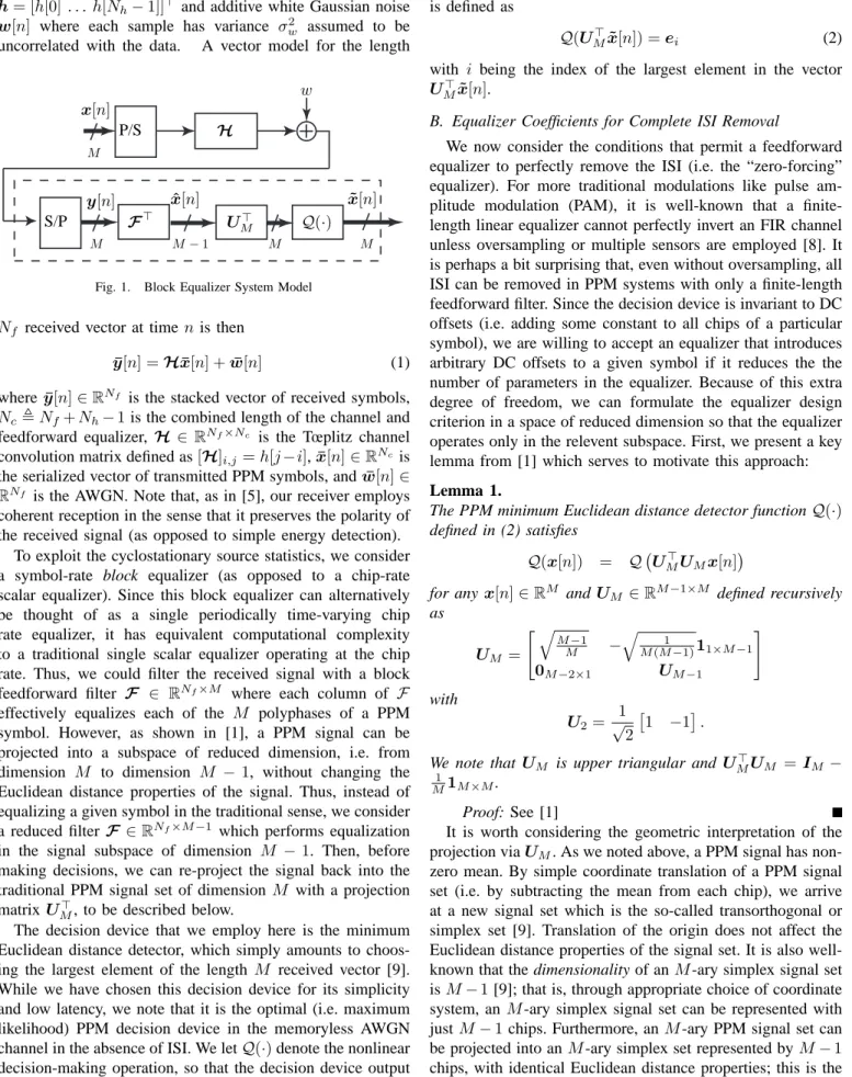
x[n] w H P/S S/P F⊤ y[n] xˆ[n] x˜[n] Q(·) U⊤ M M−1 M M M M
Fig. 1. Block Equalizer System Model Nf received vector at time nis then
¯
y[n] =Hx¯[n] +w¯[n] (1) where y¯[n]∈RNf is the stacked vector of received symbols,
Nc ,Nf+Nh−1is the combined length of the channel and feedforward equalizer, H∈ RNf×Nc is the Tœplitz channel
convolution matrix defined as[H]i,j=h[j−i],x¯[n]∈RNcis
the serialized vector of transmitted PPM symbols, andw¯[n]∈ RNf is the AWGN. Note that, as in [5], our receiver employs
coherent reception in the sense that it preserves the polarity of the received signal (as opposed to simple energy detection).
To exploit the cyclostationary source statistics, we consider a symbol-rate block equalizer (as opposed to a chip-rate scalar equalizer). Since this block equalizer can alternatively be thought of as a single periodically time-varying chip rate equalizer, it has equivalent computational complexity to a traditional single scalar equalizer operating at the chip rate. Thus, we could filter the received signal with a block feedforward filter F ∈ RNf×M where each column of F
effectively equalizes each of the M polyphases of a PPM symbol. However, as shown in [1], a PPM signal can be projected into a subspace of reduced dimension, i.e. from dimension M to dimension M −1, without changing the Euclidean distance properties of the signal. Thus, instead of equalizing a given symbol in the traditional sense, we consider a reduced filter F ∈RNf×M−1 which performs equalization
in the signal subspace of dimension M −1. Then, before making decisions, we can re-project the signal back into the traditional PPM signal set of dimension M with a projection matrix U⊤
M, to be described below.
The decision device that we employ here is the minimum Euclidean distance detector, which simply amounts to choos-ing the largest element of the length M received vector [9]. While we have chosen this decision device for its simplicity and low latency, we note that it is the optimal (i.e. maximum likelihood) PPM decision device in the memoryless AWGN channel in the absence of ISI. We letQ(·)denote the nonlinear decision-making operation, so that the decision device output can be written xˆ[n] = Q(U⊤
Mx˜[n]) where the function Q(·)
is defined as
Q(UM⊤x˜[n]) =ei (2)
with i being the index of the largest element in the vector U⊤
Mx˜[n].
B. Equalizer Coefficients for Complete ISI Removal
We now consider the conditions that permit a feedforward equalizer to perfectly remove the ISI (i.e. the “zero-forcing” equalizer). For more traditional modulations like pulse am-plitude modulation (PAM), it is well-known that a finite-length linear equalizer cannot perfectly invert an FIR channel unless oversampling or multiple sensors are employed [8]. It is perhaps a bit surprising that, even without oversampling, all ISI can be removed in PPM systems with only a finite-length feedforward filter. Since the decision device is invariant to DC offsets (i.e. adding some constant to all chips of a particular symbol), we are willing to accept an equalizer that introduces arbitrary DC offsets to a given symbol if it reduces the the number of parameters in the equalizer. Because of this extra degree of freedom, we can formulate the equalizer design criterion in a space of reduced dimension so that the equalizer operates only in the relevent subspace. First, we present a key lemma from [1] which serves to motivate this approach: Lemma 1.
The PPM minimum Euclidean distance detector functionQ(·)
defined in (2) satisfies
Q(x[n]) = Q UM⊤UMx[n]
for any x[n]∈RM andUM ∈RM
−1×M defined recursively as UM = " q M−1 M − q 1 M(M−1)11×M−1 0M−2×1 UM−1 # with U2= 1 √ 2 1 −1.
We note that UM is upper triangular and UM⊤UM =IM −
1
M1M×M.
Proof: See [1]
It is worth considering the geometric interpretation of the projection viaUM. As we noted above, a PPM signal has
non-zero mean. By simple coordinate translation of a PPM signal set (i.e. by subtracting the mean from each chip), we arrive at a new signal set which is the so-called transorthogonal or simplex set [9]. Translation of the origin does not affect the Euclidean distance properties of the signal set. It is also well-known that the dimensionality of anM-ary simplex signal set isM−1[9]; that is, through appropriate choice of coordinate system, anM-ary simplex signal set can be represented with justM−1 chips. Furthermore, anM-ary PPM signal set can be projected into anM-ary simplex set represented byM−1
chips, with identical Euclidean distance properties; this is the role ofUM. Finally, we note from [1] that projection viaUM
is invariant to DC offsets, so for some vector x ∈ RM and some scalarb,
UM(x+b1M×1) =UMx. (3) Thus, by building a block equalizer which outputs symbols
˜
x[n]∈RM−1 of reduced dimension, it is Euclidean distance preserving, and is invariant to DC shifts at the equalizer input. Next we make several definitions to aid our development of the equalizer coefficients. Again, in addition to the equalizer length Nf, the equalizer accepts one other design parameter,
∆, which represents the desired symbol delay through the channel/equalizer chain. By defining
E⊤ ∆ , 0 M×M∆ IM 0M×Nc−M(∆+1) (4) where E∆ ∈ RNc×M, we can express the delayed symbol
vector in terms of the source symbol stream as
x[n−∆] =E⊤∆x¯[n]. (5) Our goal, then, is to choose equalizer coefficients so that ˜
x[n] ≈ UMx[n −∆] where we note the appearance of
UM serves to project the source signal into the space of
reduced dimension so that it is compatible with the equalizer outputx˜[n]. Since our focus is on an equalizer with complete ISI removal, we temporarily ignore the noise, and review the conditions under which the equalizer output matches the source sequence. The ISI is eliminated if the mean square error (MSE) between the equalizer output and source signals is exactly zero in the absence of noise, or when
Jmse(F,∆) = E[||x˜[n]−UMx[n−∆]||22] (6)
= 0.
With the source autocorrelation for PPM given by Rxx , E[x¯[n]x¯ ⊤ [n]] = 1 M21Nc×Nc+ 1 M(INcM ⊗(IM− 1 M1M×M).
we defineΦ⊤xxΦxx=Rxxas the Cholesky decomposition of the source autocorrelation, where Φxx ∈ RNc−Nc/M+1×Nc.
Letting H′,HΦ⊤xxthe MSE expression reduces to [1]
Jmse(F,∆) = F ⊤ H′−UME∆⊤Φ⊤xx 2 f ro
where||·||f rodenotes the Frobenius norm. Thus, the condition
for perfect equalization is that the MSE is zero, or
H′⊤F =ΦxxE∆UM⊤. (7)
For the existence of an exact solution of F for this linear system, H′ ∈ RNf×Nc−Nc/M+1 must be tall and full rank,
leading to the following two conditions for perfect equaliza-tion:
1) Equalizer Length Condition: For F to satisfy (7) for arbitrary ∆, H′ must be a tall matrix. Hence, it is required that
Nf> Nh(M−1) (8)
2) Channel Disparity Condition: For F to satisfy (7) for arbitrary ∆,H′ must have full column rank.
Thus, the finite-length block equalizer structure can succeed in perfectly equalizing the channel, so long as the length and disparity conditions are satisfied. In the next section we consider blind adaptation of a scalar chip-rate equalizer, and subsequently show how this can be used with the block symbol-rate equalizer described above.
III. BLINDADAPTIVEALGORITHM FORPPM A. Review of Algorithm
Recently, a globally convergent blind adaptive equalization algorithm was proposed for PPM modulations [2]. The scheme employs a chip-rate FIR equalizerf ∈RNf which operates on
a zero-mean version of the received signal. That is, the mean of the received signal is subtracted before equalization, so that the equalizer output can be written x[n] =˜ f⊤(y¯[n]−µy1) where µy is the mean of the received signal. The equalizer output is then serial-to-parallel converted and fed M chips at a time into the decision device. The proposed algorithm is based on third-order moments, and adapts the equalizer coefficients to maximize the objective function
J(f) =E[˜x3[n]] (9) while constraining the norm of the equalizer taps to be 1. Intuitively, the rationale for this choice of objective function stems from the fact that a PPM signal is sparse, and is thus characterized by large skewness. Since an ISI channel serves to reduce the skewness in a PPM signal, maximizing the skewness (or third-moment) should serve to reduce the ISI in a PPM signal. It is worth pointing out that an added benefit of employing the third-moment is its insensitivity to noise [2]. As is common in the analysis of blind algorithms (e.g. [10]), the authors assume that the equalizer is sufficiently long so that the analysis can be performed in the combined channel/equalizer spacec=H⊤f. In addition, however, it is assumed in [2] that the PPM alphabet size M → ∞. Under these assumptions, the authors succeed in proving that the objective function exhibits maxima only at the desired equalizer settings, i.e. at zero-forcing (ZF) solutions. A corresponding steepest ascent algorithm emerges as f′[n+ 1] = f[n] +µ∇fJ(f) f[n+ 1] = f′[n+ 1]/ q f′⊤[n+ 1] f′[n+ 1] where the gradient in [2] is approximated by ∇fJ(f) ≈
sgn(˜x[n])˜x2[n]y[n]. We note that the true gradient is
∇fJ(f) = sgn(E[˜x3[n]])E[˜x2[n]y[n]], and thus the chosen gradient approximation is perhaps a more accurate gradient estimate of the alternate objection functionJ′
(f) =E[|x˜3[n]|] since ∇fJ ′ (f) = E[sgn(˜x3[n])˜x2[n]y[n]] = E[sgn(˜x[n])˜x2[n]y[n]] ≈ sgn(˜x[n])˜x2[n]y[n]
due to the fact that for a sufficiently small stepsizeµ, the natu-ral averaging inherent to stochastic gradient ascent algorithms effectively allows us to omit the outer expectation. Conse-quently, in the sequel, we employ a slightly more accurate gradient estimate forJ(f)yielding the update equation f[n+ 1] =f[n] +µ·sgn Pmx˜3[m] P
mx˜2[m]y[m]
(10) where the indexmon the sums is taken over the most recent
N symbols for some window sizeN. Nevertheless, to the best of our knowledge, this is the only known globally convergent algorithm for blind adaptation of equalizers used with PPM signals.
B. Discussion of Maxima for Finite M
While the results of [2] are very encouraging, the behavior of the algorithm for finite M is unclear. Some interesting questions might include:
• Do the desired maxima simply move away from the ZF solutions whenM is finite?
• If so, how far away do they move?
• Do additional false local maxima appear for finite M? Ideally, we would like to answer these questions analytically. However, without letting M → ∞, the expression for the objective function (9) cannot readily be simplified due to the appearance of many non-zero terms in the third-order moment of the PPM signal. Nevertheless, we hope to provide some evidence that, indeed, the maxima only move slightly away from the ZF solutions, and that additional false local maxima do not seem to appear.
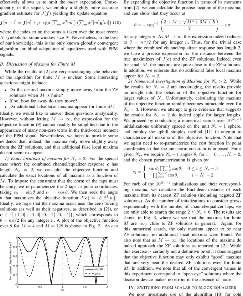
1) Exact locations of maxima forNc = 2: For the special case where the combined channel/equalizer response c has length Nc = 2, we can plot the objective function and calculate the exact locations of all maxima as a function of
M. To impose the constraint that the norm of the taps must be unity, we re-parameterize the 2 taps in polar coordinates, taking c0 = sinθ and c1 = cosθ. We then seek the angle
θ that maximizes the objective function J(c) = E[˜x3[n]]. Ideally, we hope that the maxima occur near the zero forcing solutions (as well as their negatives, as described in [2]), or c ∈ {[+1,0],[−1,0],[0,−1],[0,+1]}, which corresponds to
θ=nπ/2 for any integern. A plot of the objective function over θ forM = 4andM = 128is shown in Fig. 2. As can
0 0.5 1 1.5 2 0 0.2 0.4 0.6 0.8 1 θ/π
Normalized objective function J
M=128 M=4
Fig. 2. Objective function forNc= 2andM∈ {4,128}
be seen, the objective function only exhibits maxima near the desired ZF solutions; no additional false local maxima appear. By expanding the objective function in terms of its moments from [2], we can calculate the precise location of the maxima, and can show that they occur at
θ=−tan−1 3 +M ± √ M2+ 6M+ 5 2 ! +nπ
for any integern. AsM → ∞, this expression indeed reduces to θ = nπ/2 for any integer n. Thus, for the trivial case where the combined channel/equalizer response has length 2, we have a precise expression for the distance between the true maximizers of J(c) and the ZF solutions. Indeed, even for smallM, the maxima are quite close to the ZF solutions. In addition, we reiterate that no additional false local maxima appear for Nc= 2.
2) Numerical Investigation of Maxima for Nc>2: While the results for Nc = 2 are encouraging, the results provide no insight into the behavior of the objective function for larger values of Nc. Unfortunately, calculating the maxima of the objective function rapidly becomes intractable even for
Nc = 3. However, we attempt to give evidence that suggests the results for Nc = 2 do indeed apply for larger lengths. We proceed by conducting a numerical search over 10Nc−1
initializations uniformly spaced on the unit Nc −1 sphere, and employ the uphill simplex method [11] in attempt to characterize all maxima of the objective function. Note that we again need to re-parameterize the cost function in polar coordinates so that the unit norm constrain is imposed. For a givenNc, we requireNc−1 anglesθi fori= 0, . . . , Nc−2, and the chosen parameterization is given by:
ci=
(
sinθiQij−=01cosθj 0≤i≤Nc−3
QNc−2
j=0 cosθj i=Nc−2
.
For each of the 10Nc−1 initializations and their
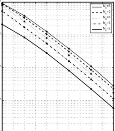
correspond-ing maxima, we calculate the Euclidean distance of each maxima from its nearest ZF solution (including negated ZF solutions). As the number of initalizations to consider grows exponentially with the number of channel/equalizer taps, we are only able to search the range2≤Nc ≤6. The results are shown in Fig. 3, where we see that the maxima for finite
M are very close to ZF solutions in general. Again, for this numerical search, the only maxima appear to be near ZF solutions; no additional local maxima were found. We also note that as M → ∞, the locations of the maxima do indeed approach the ZF solutions as reported in [2]. While this exercise is certainly not a definitive proof, it does suggest that the objective function may only exhibit “good” maxima that are very near the desired ZF solutions even for finite
M. In addition, we note that all of the convergent values in this experiment correspond to “open-eye” solutions where the decision device makes no errors in the absence of noise.
IV. SWITCHING FROM SCALAR TO BLOCK EQUALIZER We now investigate use of the algorithm (10) for cold startup of the scalar chip-rate equalizer, followed by switching
2 2.5 3 3.5 4 4.5 5 5.5 6 6.5 7 10−5 10−4 10−3 10−2 10−1 log 2(M) MSE Nc=6 N c=5 N c=4 N c=3 N c=2
Fig. 3. Proximity of maxima to ZF solutions as a function ofM
to the block symbol-rate equalizer of section II which can subsequently be adapted with decision-directed least mean squares (DD-LMS). It is well known that DD-LMS is not a good choice for cold-startup from initializations which are not open-eye. With the recent discovery of a suitable algorithm for cold-startup of a scalar equalizer [2] (and our results from section III which suggest that it always converges near a ZF solution for finite M), we expect that this algorithm can be used for cold-startup of the block equalizer.
Recall that for the blind algorithm (10), the equalizer output for a single chip of the M-PPM signal can be written
˜
x[n] =f⊤
(y¯[n]−µy1). Equivalently, we could write an entire equalized symbol as F⊤∗(y¯[n]−µy1)where
F∗= f0 ··· 0 0f ... . ..0 f ∈RNf+M −1×M . (11)
Projecting the equalized result into the relevantM−1 dimen-sional subspace gives:
˜ x[n] = UMF ⊤ ∗(y¯[n]−µy1) = UMF ⊤ ∗ | {z } ,F⊤ init ¯ y[n]
where we use the fact that UMF
⊤
∗1 = 0 which follows
from (3). A candidate cold startup-scheme for M-PPM then emerges:
1) Adapt a scalar chip-rate equalizer f using (10). 2) After sufficient number of iterations, some form of
symbol synchronization (i.e. identification of symbol boundaries) needs to be performed. This amounts to an M-ary hypothesis testing problem which could be solved by choosing the symbol boundary so that all symbols to have roughly equal power.
3) We then switch to using the block symbol-rate equalizer with the equalizer coefficients set toF=F∗UM⊤ where F∗ is defined in (11).
4) Adaptation of the block equalizer can then proceed using DD-LMS via
F[n+ 1] = F[n]−µy¯[n](x˜[n]−UMxˆ[n])
⊤
where µ is a small positive step-size which serves to average out the noise in the gradient estimate.
V. NUMERICALRESULTS ANDCONCLUSION A simulation was conducted using 4-PPM transmission over 1000 randomly generated Rayleigh WSSUS channels with length Nh = 10 and 10 dB SNR. The equalizer length was chosen to beNf = 30. The startup procedure outlined above was employed, where the blind algorithm in step 1 was given 1000 PPM symbols before switching to the decision-directed block equalizer. We note that DD-LMS will in general con-verge to the MMSE equalizer solution, and not the ZF solution. Nevertheless, for each of the 1000 channel realizations, we observed the ability of the cold startup scheme to sufficiently open the eye so that there would be no errors if the noise were removed. As hoped, the equalizer succeeded in opening the eye for all 1000 realizations, suggesting that indeed the cold startup procedure is a good candidate for use with the block equalizer structure.
We have presented a cold-startup strategy which combines the techniques presented in [1] and [2], and seems to be a promising choice for blind equalization of PPM signals. Future work could characterize (or bound) the exact locations of the maxima of (9), and show that they lie in the regions of convergence for DD-LMS, thus providing more analytical evidence in support of this cold-startup strategy.
REFERENCES
[1] A. Klein and P. Duhamel, “Decision-feedback equalization for pulse-position modulation,” IEEE Trans. Signal Process., vol. 55, pp. 5361– 5369, Nov. 2007.
[2] P. P¨a¨aj¨arvi, “Blind equalization using third-order moments,” Ph.D. dissertation, Lulea tekniska universitet, Sweden, May 2008. [Online]. Available: http://pure.ltu.se/ws/fbspretrieve/1918433
[3] M. Audeh, J. Kahn, and J. Barry, “Decision-feedback equalization of pulse-position modulation on measured nondirected indoor infrared channels,” IEEE Trans. Commun., vol. 47, pp. 500–503, Apr. 1999. [4] M. Z. Win and R. A. Scholtz, “Ultra-wide bandwidth time-hopping
spread-spectrum impulse radio for wireless multiple-access communi-cations,” IEEE Trans. Commun., vol. 48, pp. 679–689, Apr. 2000. [5] J. Barry, “Sequence Detection and Equalization for Pulse-Position
Mod-ulation,” in Proc. IEEE International Conference on Communications (ICC’94), May 1994, pp. 1561–1565.
[6] C. Carbonelli and U. Mengali, “M-PPM noncoherent receivers for UWB applications,” IEEE Trans. Wireless Commun., vol. 5, p. 22852294, Aug. 2006.
[7] M. Audeh, J. Kahn, and J. Barry, “Performance of pulse-position modulation on measured non-directed indoor infrared channels,” IEEE Trans. Commun., vol. 44, pp. 654–659, Jun. 1996.
[8] L. Tong, G. Xu, and T. Kailaith, “Fast blind equalization via antenna arrays,” in Proc. IEEE Intl. Conf. on Acoustics, Speech, and Signal Processing (ICASSP’93), Apr. 1993, pp. 272–275.
[9] J. Proakis, Digital Communications, 4th ed. New York: McGraw-Hill, 2000.
[10] G. Foschini, “Equalizing without altering or detecting data,” Bell Sys. Tech. J., vol. 64, pp. 1885–1911, Oct. 1985.
[11] M. Avriel, Nonlinear Programming: Analysis and Methods. Dover Publishing, 2003.