Resilient Virtual Clusters
Michael Le, Israel Hsu, Yuval TamirConcurrent Systems Laboratory UCLA Computer Science Department
{mvle,israel,tamir}@cs.ucla.edu
Abstract—Clusters of computers can provide, in aggregate,
reliable services despite the failure of individual computers. System-level virtualization is widely used to consolidate the workload of multiple physical systems as multiple virtual machines (VMs) on a single physical computer. A single physical computer thus forms a virtual cluster of VMs. A key difficulty with virtualization is that the failure of the virtualization infrastructure (VI) often leads to the failure of multiple VMs. This is likely to overload ‘‘cluster computing’’ resiliency mechanisms, typically designed to tolerate the failure of only a single node at a time. By supporting recovery from failure of key VI components, we have enhanced the resiliency of a VI (Xen), thus enabling the use of existing ‘‘cluster computing’’ techniques to provide resilient virtual clusters. In the overwhelming majority of cases, these enhancements allow recovery from errors in the VI to be accomplished without the failure of more than a single VM. The resulting resiliency of the virtual cluster is demonstrated by running two existing ‘‘cluster computing’’ systems while subjecting the VI to injected faults.
Keywords: Virtualization, Cluster, Reliability, Recovery, Microreboot, Middleware
1. Introduction
Decades of developments in ‘‘cluster computing’’ and ‘‘distributed systems’’ hav e enabled the implementation of clusters of computers for high-performance server and HPC applications, operating reliably despite the failure of individual computers. The fault tolerance mechanisms used in these clusters rely on the confinement of the impact of faults within the physical nodes where they occur.
Improvements in processor performance as well as hardware and software support for system-level virtualization are enabling the consolidation of the workload of multiple physical systems as multiple virtual machines (VMs) on a smaller number of physical computers. This is done while maintaining performance, security, and fault isolation among VMs and providing enhanced manageability features [28, 4, 29]. A small number of computers thus forms a virtual cluster of a much larger number of VMs as the virtual cluster nodes. Applications and middleware developed for physical clusters can be deployed, unmodified, on such a virtual cluster. The virtual machine monitor (VMM) is a key component of the virtualization infrastructure (VI) software that multiplexes the resources of a single computer among multiple VMs.
A major disadvantage of the virtual cluster architecture is that a single hardware fault or a defect in the VI software (e.g., a Heisenbug[7]) can lead to the failure of multiple virtual nodes by, for example, preventing VMs from being scheduled or preventing VMs from accessing I/O devices. This is likely to overwhelm the fault tolerance mechanisms designed for physical clusters. Hence, a key to enabling the deployment of virtual clusters is to enhance the resiliency of the VI to faults in the hardware or virtualization software.
It is difficult or impossible to prevent a single permanent hardware fault from leading to the failure of multiple virtual nodes of a virtual cluster. Howev er, with respect to a single
transient hardware fault or a defect in the VI software, there is
the potential for enhancing the resiliency of the VI using only software modifications of the VI, thus minimizing the probability of the failure of multiple virtual nodes. The design, implementation, and evaluation of such VI enhancements is the focus of this paper.
Previous works have inv estigated mechanisms for tolerating failures of different components of the VI. In particular, this has included recovery of driver VMs (DVMs), which provide VMs safe access to shared physical I/O devices [6, 17, 15, 12], and recovery from VMM failures [16]. However, these works focused on a single component of the VI in isolation, and their evaluations were based on micro-benchmarks or other simple workload configurations. There has been no evaluation of how multiple VI resiliency mechanisms work together. Furthermore, there has been no evaluation of the extent to which these mechanisms enable leveraging of existing middleware for fault-tolerant ‘‘cluster computing.’’
This paper presents our enhanced version of the Xen [2] VI with support for recovery from both DVM and VMM failures. This VI is used to deploy a virtual cluster running the
Ghidrah fault-tolerant middleware for compute-intensive
parallel applications [18, 19] as well as the Linux Virtual
Server (LVS)[30] middleware supporting scalable load balanced highly-available web service. In each case, the existing middleware has an ability to tolerate the failure of a single cluster node.
The resiliency enhancements to the VI are ‘‘successful’’ if they limit the impact of faults in the VI that are manifested as errors. Specifically, the goal is for the two cluster workload configurations to be able to operate as they do on a physical cluster, maintaining system operation despite faults.
We use our Gigan fault injector [14] to inject faults in key components (DVMs and the VMM) of the enhanced Xen VI. Our experiments show that the VI enhancements are ‘‘successful’’ for over 92% of the faults in the VI that are manifested as errors. Furthermore, as explained in Section 5.4, since not all CPU cycles are spent executing VI code and not all faults in the VI manifest as errors, the probability of system failure due to a single random fault occurring in a CPU while it is non-idle is less than 0.3%. The implication of this result is that virtual clusters with properly enhanced VIs can serve as a platform for cluster computing workloads requiring high reliability.
The rest of the paper is organized as follows. The next section describes the main components of the VI. Section 3 presents the detection and recovery mechanisms used to tolerate failures of the VI. Section 4 describes the experimental setup for the fault injection campaigns and presents an overview of the two cluster workloads. Results and analysis of the fault injection campaigns are presented in Section 5. Related work is discussed in Section 6.
Figure 1: Virtualization infrastructure and the split device driver architecture.
2. System-Level Virtualization
System-level virtualization allows multiple VMs, each with its own OS, to run on a single physical computer [28]. The
virtualization infrastructure (VI) consists of all the software
components involved in multiplexing hardware resources among VMs. The VI isolates VMs from each other, so that activities in one VM cannot affect another VM [27]. We refer to VMs that are not part of the VI as application VMs (AppVMs). In the context of a virtual cluster, AppVMs are the virtual cluster nodes.
A common VI organization for allowing multiple VMs to share I/O devices is called the split device driver architecture [6, 17, 23]. With this organization, a frontend
driver resides in each VM sharing a device. As shown in
Figure 1, the actual device driver together with a backend
driver reside in a VM that is referred to as the Driver VM
(DVM). In each AppVM, I/O requests are forwarded by the frontend driver to the backend driver, which invokes the actual device driver. In Xen [2], the frontend and backend drivers communicate through a ring data structure in an area of memory shared between the AppVM and DVM. Multiple AppVMs share a single device by having multiple frontend
drivers connect to a single backend driver. A DVM can support multiple drivers, and the VMM supports multiple DVMs, with each DVM hosting access to different devices.
A unique privileged VM (PrivVM) can invoke system management operations of the VMM, including creating and destroying VMs, attaching devices to DVMs, and pausing and unpausing VMs. The VMM does not permit these operations to be invoked by any other VM.
3. Resiliency to VI Failures
This section briefly describes our resiliency enhancements to the Xen VI. While some of these enhancements have been presented before [15, 12, 16], they are described here to facilitate understanding of the overall system and the experimental results. The DVM recovery mechanism for block devices has not been presented in prior work. Our VI enhancements do not require modification of the applications or cluster middleware. There are two goals for these enhancements: 1) to maintain the operation of the VI despite faults that are manifested as errors in the VMM or DVMs, and 2) to limit the impact of faults in the VI that are manifested as errors so that they do not result in the failure of more than one AppVM. The second goal is important since cluster middleware is typically designed to tolerate the failure of only a single node at a time.
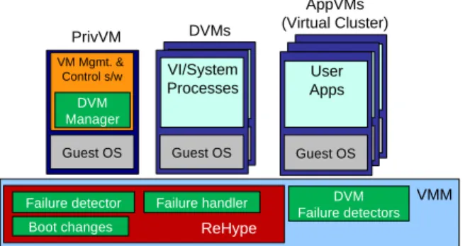
Figure 2: The virtualized system with the resiliency enhancements of the VI and the virtual cluster.
Figure 2 shows the main components of a virtualized system with the resiliency enhancements of the Xen VI and a virtual cluster as multiple AppVMs. The VI resiliency enhancements include ReHype [16] for detecting and recovering from VMM failure, two DVMs to enable uninterrupted access to devices for the AppVMs, a DVM Manager for controlling recovery from DVM failure, and DVM failure detectors for detecting and informing AppVMs and the DVM Manager of DVM failure [15, 12].
We hav e not implemented mechanisms for recovery from PrivVM failure. Once the virtual cluster’s VMs have been created, the PrivVM is not used during fault-free execution. This is verified by the results of system profiling, presented in Section 5. Since the PrivVM is mostly idle, the probability of its failure is much lower than for other VI components.
3.1. Resilience to VMM Failure with ReHype
Failure of the VMM generally results in the failure of all the system’s VMs. Recovery from such a failure typically involves rebooting the entire system — a slow process that involves the loss of the work in progress in all the VMs. ReHype [16] is designed to detect and recover from failure of the Xen VMM without losing the state of the VMs. ReHype avoids rebooting the entire system by performing a ‘‘microreboot’’ of only the VMM. VMs are paused during the VMM reboot and resume normal execution once the new VMM instance is running.
ReHype detects VMM failure when the VMM’s panic handler is invoked or when a watchdog timer based on a counter that is regularly incremented by the VMM expires.
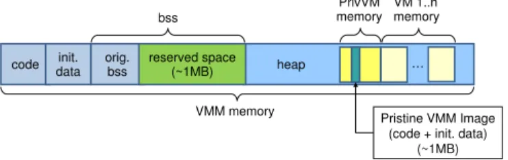
Figure 3: System memory layout with ReHype.
Performing a microreboot of the VMM involves refreshing parts of the VMM memory with a pristine VMM image stored elsewhere in memory. The overwritten memory includes VMM code, the initialized static data segment, and the original uninitialized (bss) static data segment (Figure 3). Before refreshing VMM memory, VMM state in the static data segments is preserved since it contains data that is critical for resuming execution of the existing VMs. ReHype reserves a space in the bss to which this state is copied and from which it is later restored.
To prevent the loss of VM states across a VMM microreboot, the memory of the VMs, which is allocated on the VMM’s heap, must be preserved. The memory states of VMs can be very large. Hence, to minimize recovery time, the VMM’s heap is preserved in place. The VMM’s boot code has been modified to restore critical VM management data structures, saved in the reserved space in the bss and the preserved heap, and to avoid marking as free pages that were allocated by the old VMM instance.
Once a new VMM instance has been booted, a number of inconsistencies between the new VMM instance and the rest of the system must be resolved. For example, acquired locks in the preserved structures must be released and hypercalls that were interrupted by the failure must be retried. These and other inconsistencies, as well as their resolution in ReHype, are described in detail in [16].
3.2. Recovery from DVM Failures
If a DVM fails, AppVMs that have been accessing I/O devices through this DVM lose their access to the I/O devices. DVM crashes are detected when the crash handler in the DVM’s kernel makes a hypercall to the VMM or when the VMM responds to illegal DVM activity by killing the DVM. DVM hangs are detected when the DVM stops context switching among processes or when the DVM stops consuming requests on its shared rings with AppVMs [15].
The simplest way to recover from a DVM failure is to reboot the failed DVM and establish a connection between the new DVM instance and the AppVMs. However, while the DVM is rebooting, the AppVMs that have been using the DVM cannot access I/O devices. Unfortunately, long latencies of an AppVM’s I/O requests can cause applications to fail.
To avoid the long recovery latency, our system uses two active DVMs, each controlling a different device. There are two options for managing the two DVMs with their respective devices: 1) as a primary and ‘‘warm spare,’’ or 2) actively use both DVMs, with the ability to degrade to using only one without loss in basic functionality.
With the first option above, upon detection of a DVM failure, a signal is sent to all the frontend drivers connected to backend drivers in the failed DVM. Each frontend driver handles the signal by disconnecting from the failed backend driver and connecting to the spare backend driver on the designated spare DVM. Since the spare DVM has a ‘‘warm spare’’ device, the AppVMs’ I/O requests can be immediately serviced without waiting for the device of the failed DVM to be reset. Once the failed DVM has been rebooted, the associated frontend drivers are notified by the VI so that they can switch their connections back to the newly-recovered backend drivers.
While the first option described in the previous paragraph is used for connection to network interfaces (this basic approach is described in [12]), the second option (actively using both DVMs) is used for block devices (access to disks). In this case, the device (the disk) has state that must be accessible following recovery. Hence, we use software RAID-1, implemented in the AppVM guest OS, to provide continuous access to the data despite the failure of one of the DVMs. Each disk of the RAID-1 configuration is controlled by a separate DVM and backend driver.
The RAID software of the AppVM guest OS detects disk failure based on error codes returned from block requests and on timeouts of block requests. Unfortunately, Xen’s block frontend and backend drivers do not implement timeouts. To work around this problem, we have modified the block frontend driver to receive an alert from the VMM when the DVM of its backend driver has failed. The frontend driver responds to the alert by marking all pending block requests as failed, causing the RAID software to mark the device as failed. Once the failed DVM is rebooted, the frontend drivers are
notified by the VMM to reconnect to the backend. The RAID software is then informed to re-form the RAID configuration.
4. Experimental Setup
To evaluate the effectiveness of our VI resiliency enhancements, we injected faults during the execution of VI code with the virtual cluster hosting two different workloads: (1) the Ghidrah Byzantine fault-tolerant cluster manager, and (2) the Linux Virtual Server (LVS) providing highly-available web service. This section describes the fault injection campaign as well as the two cluster workloads along with their fault tolerance mechanisms.
4.1. Fault Injection Campaign
The general configuration of the virtualized system, including the virtual cluster, is shown in Figure 2. The virtual cluster nodes run as AppVMs. There are two DVMs, each controlling a NIC and a SATA disk controller.
The fault injection campaign consists of many fault injection runs. A ‘‘run’’ begins by booting the VMM, PrivVM, DVMs, and the virtual cluster nodes (AppVMs). After the cluster nodes begin executing the cluster workload, a single fault is injected into the VMM or one of the DVMs. The duration of a run is long enough to provide sufficient time for the system to recover from failure and for the cluster workload to complete and produce results.
To simplify the setup for software-implemented fault injection, the entire target system of Figure 2 runs inside a fully-virtualized (FV) VM [14]. The FV VM setup also simplifies restoration of pristine system state before each run, which is needed to isolate the next run from the effects of fault injections of prior runs. The entire target system is restarted by rebooting the FV VM.
As discussed in Section 3, each AppVM uses a software RAID-1 device for its root file system. To decrease the time of restoring pristine disk images for each fault injection run, a stackable union file system (AUFS [25]) is used [11]. Each AppVM creates two RAID-1 devices, one containing the pristine disk state as a read-only branch and the second containing a smaller empty write branch. These file system branches are stacked to form a single writable root file system for the cluster node.
The cluster middleware of both Ghidrah and LVS can tolerate the loss of a cluster node and continue to operate correctly. They also can reintegrate a newly rebooted node into the system. In our virtual cluster, a user-level process that runs in the PrivVM is responsible for restoring a failed node. The cluster middleware logs detection of node failures. This log is monitored by the process in the PrivVM, which then reboots the failed node (AppVM) by invoking VM management commands.
We use the UCLA Gigan fault injector [14, 11] to inject
single bit flip faults into registers (general purpose and the program counter) while CPUs are executing VMM and DVM (user and kernel level) code. While these injected faults do not accurately represent all possible faults, they are a good choice since transient hardware faults in CPU logic and memory are likely to be manifested as erroneous values in registers. Furthermore, these faults can cause arbitrary corruptions in the entire system.
Tw o fault injection campaigns are run: 1) injecting faults while the CPU executes VMM code, and 2) injecting faults while the CPU executes DVM code (user and kernel). During a fault injection run, an injection is triggered at a randomly selected time, in the range of 500ms to 6.5s after the cluster begins running its applications. To ensure that the injection occurs only when the VMM or DVM is executing, a fault is only injected after the designated time has elapsed and 0 to 20,000 VMM or DVM instructions, chosen at random, have been executed. The injection is a single bit-flip into a randomly selected bit of a randomly selected register. Each VMM injection selects randomly from among all the CPUs of the target system. For DVM injections, only CPUs running the DVMs are selected for injection. Over 1400 faults are injected for each workload and for each campaign.
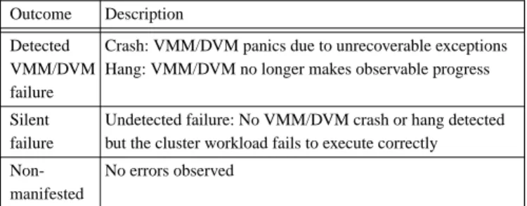
Table 1. Impact of a fault on system components.
Outcome Description Detected
VMM/DVM failure
Crash: VMM/DVM panics due to unrecoverable exceptions Hang: VMM/DVM no longer makes observable progress Silent
failure
Undetected failure: No VMM/DVM crash or hang detected but the cluster workload fails to execute correctly No errors observed
Non-manifested
As summarized in Table 1, the possible consequences of an injection are: detected (VMM/DVM crash or hang), silent (undetected failure), or non-manifested. A crash occurs when the VMM or DVM panics due to unrecoverable exceptions. VMM and DVM hang detection mechanisms are explained in Section 3.1 and Section 3.2, respectively. A silent VMM/DVM failure occurs when no VMM/DVM hang or crash is detected but the cluster workload fails to execute correctly. What constitutes incorrect execution is specific to the cluster workload and is discussed in more detail in the following subsections. Non-manifested means that no errors are observed.
Ultimately, the critical question is whether the system (the entire virtual cluster) continues to operate correctly. If a VMM or DVM failure is detected but the VI recovery mechanisms fail to restore the VI to working order, the cluster workload fails to complete and produce the correct results. In this case, the outcome of the injection run is a system failure. Furthermore, if the impact of a fault is ‘‘silent failure,’’ as discussed above, the outcome of the injection run is also a
system failure. In all other cases, there is no system failure
since either the fault is not manifested in any way or the combination of the VI resiliency mechanisms and the cluster middleware resiliency mechanisms are successful in restoring the system to working order.
4.2. The Ghidrah Cluster Manager
With clusters for parallel tasks, cluster management middleware (CMM) performs critical functions in the operation of a cluster, including allocating resources to user tasks, scheduling tasks, reporting task status, and coordinating fault handling for tasks. The Ghidrah CMM was developed at UCLA with aggressive fault tolerance capabilities in order to reliably perform these functions in support of a data-processing cluster operating in space [18, 19].
Figure 4: Logical structure of the Ghidrah CMM. The overall structure of Ghidrah is shown in Figure 4. The system consists of three components: a replicated centralized manager, an agent on each compute node, and a ‘‘trusted computer’’ called the Spacecraft Control Computer (SCC). Ghidrah supports running multiple parallel applications with gang scheduling; circles in Figure 4 represent processes of three user tasks (T1, T2, and T3). The Manager Group performs cluster-level decision making, such as scheduling and fault management. It is composed of three Manager Replicas, using active replication [18] to tolerate a single Byzantine-faulty node. An Agent on each node reports node status to the Manager Group and performs commands at the node on behalf of the Manager Group. The SCC, which is not part of the cluster, is the ‘‘hard core’’ of the system. It can power-reset individual nodes based on information received from the Manager Replicas as well as power-reset the entire cluster. Ghidrah is designed to maintain the basic cluster functionality despite any single faulty cluster node.
If a fault causes a process of a user task to crash, the Manager Group notifies all the processes of the task. In the experimental setup used here, the surviving processes respond by requesting the Manager Group to restart the user task.
We run Ghidrah on a cluster of four virtual nodes. The SCC is emulated by a remote node outside of the virtualized system. The application workload consists of two gang-scheduled instances of the IS (integer sort) benchmark in the NAS Parallel Benchmark Suite [1], both running across four
nodes. IS was chosen since it is communication-intensive, thus stressing the DVMs as well as the VMM.
For the injection campaign on the Ghidrah workload, there are two modes of incorrect execution that indicate a
system failure as defined in Section 4.1: (1) an instance of the
IS benchmark stops executing or generates incorrect results, and (2) the SCC power-resets the entire cluster, indicating that the Manager Replicas failed to generate correct status reports to the SCC.
4.3. The Linux Virtual Server
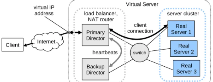
The Linux Virtual Server (LVS) is an open-source load-balancing solution for building highly scalable and highly available servers using clusters of servers [30, 20]. It is widely deployed in industry for online services such as web and FTP servers. (Note that the term ‘‘virtual server’’ here is unrelated to system virtualization technology). We use the LVS/NAT configuration shown in Figure 5 to provide highly available web service. Clients connect to the virtual server by using a virtual IP address that is owned by the LVS director node. The director forwards clients’ requests to one of the real servers in the server cluster. The real servers are Apache web servers.
Figure 5: Structure of Linux Virtual Server with primary and backup directors and three real servers.
Since the director node can be a single point of failure, LVS configuration typically involves the use of primary and backup directors. We use the open-source keepalived project to deploy a primary and one backup director. Periodic heartbeats between the primary and backup directors are used to detect when either director has failed. Upon failure of the primary director, the backup director assumes the role of the primary director. The LVS director also periodically checks for the liveness of the real servers by forming a TCP connection with each server. Failure to form a TCP connection causes the server to be removed from the pool of servers for handling requests. New or recovered (rebooted) real servers are automatically added to the server pool.
Our virtual server cluster is configured for two directors and three real servers. The client runs on a remote node outside of the virtualized system. To stress the virtual cluster, the client executes fiv e instances of the Apache ab benchmark. Three of the fiv e instances each perform a series of about 1300 HTTPS requests for a static 10KB file. The remaining two
instances each perform a series of about 300 HTTPS requests for a dynamic 10KB file generated by invoking a program on the server that performs a series of disk I/O operations.
The LVS cluster is considered to have failed if it is unable to service web requests. However, LVS director and server failover inv olves terminating client connections. Any time a director or real server fails, existing client connections through the director or with the real server are terminated. Furthermore, in the case that a new director becomes the new primary director, all connections must be terminated and re-formed using the new primary director. Hence, for the injection campaign on the LVS cluster, we define a system
failure as occurring when a client experiences more than two
connection timeouts during a single injection run.
5. Results
This section presents the results of the fault injection campaigns. As discussed in Section 4, injections were done while the system was executing VMM code as well as DVM code. For each injection target, there is a discussion of the errors caused by the faults and an analysis of the causes of system failure. The contributions of the different fault tolerance mechanisms is presented along with a discussion of the overall resiliency of the virtual cluster.
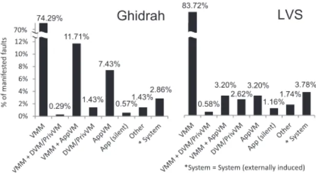
0.29% 11.71% 1.43% 7.43% 0.57% 1.43% 2.86% 0% 2% 4% 6% 8% 10% 12% 14% Ghidrah 74.29% 0.58% 3.20% 2.62% 3.20% 1.16% 1.74% 3.78% LVS 83.72%
*System = System (externally induced) 70% % o f m an if es ted f au lt s
Figure 6: Distribution of component failures caused by injecting faults into CPU registers during VMM execution. Note that left-most bars are not shown to scale.
5.1. Fault Injection into VMM
Some of the injected faults are manifested as errors — some component of the system deviates from correct operation (component failures). Figure 6 shows the distribution of component failures caused by injected faults that are manifested as errors for Ghidrah and LVS. With both cluster workloads there is a similar distribution of component failures. Not too surprisingly, when faults are injected during VMM execution, the majority of faults manifest as VMM failure. A single fault during VMM execution can cause other system components to fail together with the VMM. For example, with Ghidrah and LVS, about 12% and 3%, respectively, of manifested faults caused a VMM failure that led to an AppVM failure. A fault in the VMM can also manifest as a failure of a DVM, PrivVM, or AppVM without causing a detected VMM
failure. These manifestations are caused by the failure of the VMM to correctly execute hypercalls on behalf of the VMs. As a result, incorrect return values are provided to the VMs, which can result in a VM kernel panic.
Faults in the VMM can also manifest as silent application failures (‘‘App (silent)’’). These faults do not cause a detectable failure in the VI but cause Ghidrah and LVS to fail. Such silent application failures are rare (less than 1.2%) for both workloads. The ‘‘Other’’ category in Figure 6 includes several miscellaneous types of manifestations, each of which occurs very rarely.
A small fraction of manifested faults fall into the category of ‘‘System (externally induced)’’. This type of manifestation is a result of the outer VMM (the external entity in our experimental setup) terminating the target VM. The outer VMM may terminate the VM if it cannot safely access the VM’s memory to perform some operations on its behalf (possibly due to state corruption) or if the VM caused a triple fault exception to occur. A triple fault exception is generated if a fault is triggered while trying to invoke the double fault handler. Such exceptions can be caused by a corrupted page directory or segmentation table in the target VM.
Table 2. VMM fault injection results for Ghidrah and LVS. Percentage of successful application completion out of all manifested faults.
Cluster Successful Application
Completion Rate 91.7% Ghidrah
90.7% LVS
Due to the various resiliency enhancement mechanisms in the system, a large fraction of the component failures discussed above do not result in system failure (the system maintains correct operation). This fraction is shown in Table 2. Specifically, the virtual cluster running Ghidrah and LVS continues to operate correctly for over 91% and 90%, respectively, of manifested VMM faults. Without VI resiliency enhancements, the virtual cluster running Ghidrah and LVS would continue to operate correctly for only 7.4% and 3.2%, respectively, of manifested VMM faults. This is because the cluster middleware would only be able to tolerate faults in the VMM that manifest as failure of a single AppVM. The distribution of component failures leading to system failure is shown in Figure 7. With Ghidrah and LVS, approximately 60% and 50%, respectively, of system failures are caused by unsuccessful recovery from the detected failure of a VI component (these numbers exclude ‘‘App (silent)’’ and ‘‘System (externally induced)’’). For Ghidrah, there is a relatively large fraction of system failures caused by the failure of more than one component of the VI (˜34%). Further analysis reveals that after a VMM failure and subsequent reboot of the VMM, two AppVMs fail shortly thereafter. The
20.69% 3.45% 34.48% 6.90% 34.48% 0% 5% 10% 15% 20% 25% 30% 35% 40% Ghidrah 21.88%25.00% 12.50% 40.63% LVS
*System = System (externally induced)
% o f sy st em f ai lu res
Figure 7: Distribution of component failures leading to system failure. Component failures caused by injecting faults into CPU registers during VMM execution.
kernel of the two AppVMs panicked due to a failed assertion in the network frontend driver. This failure scenario is observed at a lower frequency with LVS, possibly due of the differences in network traffic patterns between the two cluster applications. In addition, approximately 20% of system failures for both cluster workloads are caused by the failed recovery of the VMM. Many of these unsuccessful cases are due to the VMM accessing corrupted data after the VMM is rebooted, thus immediately causing another failure. Other system failures are caused by a failed PrivVM, which our mechanisms do not yet tolerate.
With both Ghidrah and LVS, more than 40% of system failures are caused by undetected VI component failures. This includes cases that are externally induced and silent application failures. For both cluster workloads, more than a third of system failures are caused by the outer VMM terminating the target system VM (externally induced). Over 90% of these externally induced system failures are caused by a triple fault exception. On actual hardware, a triple fault exception will force a hardware system reset. The outer VMM terminating the target VM correctly emulates this behavior.
For the results presented so far, injections were uniformly distributed across CPUs. However, a fault injected in a CPU that spends a large fraction of its cycles executing VMM code is more likely to lead to VMM failure than a fault injected in a CPU that spends a smaller fraction of its cycles executing VMM code. Since the activities in VMs differ, the fraction of cycles spent executing VMM code is not the same across the CPUs hosting these VMs. Hence, it is important to evaluate whether the results are qualitatively different if the distribution of fault injections is adjusted to match the fraction of time each CPU spends executing VMM code.
With our setup, each VM runs on a single virtual CPU (VCPU) and each VCPU is pinned to a particular physical CPU. Table 3 shows the distribution of VMM execution across the CPUs, measured using the Xenoprof profiler [21]. The probability that a manifested fault leads to system failure can be computed using the VMM execution distribution, the manifestation rate for a fault in each of the CPUs, and the probabilities of a fault in each of the CPUs leading to system failure. Based on this, the probabilities of correct application
Table 3. Distribution of CPU time spent executing VMM code. PrivVM pinned to CPU 0. DVMs are pinned to CPUs 1 and 2. Ghidrah - each of the four AppVMs are pinned to a single CPU (3-6). LVS - primary and backup directors share CPU 3 and each of the three servers are pinned to a single CPU (4-6).
CPUs
0 1 2 3 4 5 6
Cluster
Ghidrah 10.8% 33.2% 32.2% 5.6% 6.6% 6.7% 4.9%
LVS 10.2% 18.1% 7.8% 3.2% 20.5% 19.8% 20.4%
completion given that a fault has manifested, with Ghidrah and LVS, are 90.8% and 91.3%, respectively. These results are similar to those presented in Table 2. Furthermore, since the manifestation rates across CPUs are similar, the probabilities of correct application completion given a fault are also similar when taking into account the actual execution distribution compared to uniform distribution: 97.8% vs. 97.9% in both cases with Ghidrah, and 98.0% vs. 97.8% with LVS. Hence, in this case, taking into account the fraction of time each CPU spends executing VMM code does not change the results qualitatively. 0.61% 0.40% 1.62% 0% 2% 4% 6% 8% 10% 12% 14% DVM + AppVM DVM AppVM App (silent) Ghidrah 97.37% 9.79% 0.93% 2.10% DVM + AppVM DVM AppVM App (silent) LVS 87.18% 85% % o f m an if es ted f au lt s
Figure 8: Distribution of component failures caused by injecting faults into CPU registers during DVM execution.
5.2. Fault Injection into DVMs
Figure 8 shows the distribution of component failures caused by faults injected while DVM code is executed. The vast majority of faults manifest as only a DVM failure. An AppVM kernel panic can occur when handling a malformed I/O response from a corrupted DVM. With LVS, a large fraction of AppVM failures (91%) are caused by the inability of the director to ‘‘ping’’ one of the servers. This ping failure (due to a failed DVM) results in a server being marked as failed and rebooted. A corrupted DVM can also cause arbitrary corruption to the device state and generation of incorrect I/O responses. This faulty behavior may not cause a DVM to crash or hang but does result in application failures.
Table 4 shows the fraction of the component failures, caused by DVM injections, that do not result in system failure. The successful application completion rate is higher than when the same type of injection is performed during VMM execution. The main reason is that, as shown in Figure 8, the VMM is able to isolate DVM failure from affecting other components of the virtualized system. Figure 8 also shows that, without VI fault tolerance mechanisms, the virtual cluster
running Ghidrah or LVS would continue to operate correctly for less than 1% of manifested DVM faults.
Table 4. DVM fault injection results for Ghidrah and LVS. Percentage of correct application operation out of all manifested faults.
Cluster Successful Application
Completion Rate 97.8% Ghidrah 97.0% LVS 15.38% 84.62%
>1 Component App (silent)
LVS 27.27% 72.73% 0% 10% 20% 30% 40% 50% 60% 70% 80% 90%
>1 Component App (silent)
Ghidrah % o f sy st em f ai lu res
Figure 9: Distribution of component failures leading to system failure. Component failures caused by injecting faults into CPU registers during DVM execution.
Figure 9 shows the distribution of component failures leading to system failure. The majority of system failures, over 70% and 80% for Ghidrah and LVS, respectively, are the result of silent application failures. A failed DVM can cause corruption of data written to or read from I/O devices, thus causing corruption of application data. For example, in our experiments, web clients accessing LVS issue requests that require the web server running under LVS to perform disk accesses. Many silent application failures resulting from DVM injections involve the client receiving corrupted data from the server. A failed DVM can also block the flow of network traffic. With LVS, this can cause a client to time out waiting for responses from the servers. With Ghidrah, this can lead to missing heartbeats from the managers replicas. Besides silent application failures, DVM faults cause system failures when they lead to the failure of a DVM and an AppVM together, overwhelming the DVM fault tolerance mechanism, designed to handle one VM failure at a time. In addition, with Ghidrah, there are two cases in which a system failure occurred despite a successful recovery of a failed DVM. These cases appear to be the result of a bug in Ghidrah. The CPU loads for the two DVMs are not identical. With Ghidrah, the percentages of CPU time spent executing DVM1 and DVM2 code (user-level and OS) are 49.2% and 50.8%, respectively. With LVS, the percentages are 64.8% and 35.2%, respectively. With LVS, DVM1 is utilized more than DVM2 since all three servers and the primary director use DVM1 as their primary network backend. This is done to minimize the overhead for network communication between the servers and primary director. As in Section 5.1, we evaluate the impact of the uneven load on the two DVMs. Since the load is almost identical with Ghidrah, we focus on LVS. As with VMM injection, the results obtained by
adjusting the fraction of fault injections based on DVM execution times are similar to the results based on uniform injection distribution: 97.0% correct operation rate for manifested faults. The probabilities of correct applications completion given a fault in a DVM are also the same, at 99.1%, for both the actual execution distribution and uniform execution distribution.
Table 5. CPU utilization of the VI running Ghidrah and LVS. Total CPU utilization is all non-idle CPU cycles over all CPU cycles. % of non-idle cycles in VI is all CPU cycles in VI over all non-idle CPU cycles.
VI Breakdown VMM DVMs PrivVM
Cluster Total CPU
Utilization
% of non-idle cycles in VI
Ghidrah 30.5% 15.3% 45.5% 51.8% 2.6%
LVS 27.7% 16.3% 64.1% 31.4% 4.5%
5.3. Impact of Different FT Mechanisms
This subsection analyzes the contributions of individual VI resiliency mechanisms to the prevention of system failure. Also analyzed are the contributions of the fault tolerance mechanisms of the cluster middleware running on the virtual cluster. The results in this section utilize the breakdown of CPU cycles usage shown in Table 5. Calculations are performed based on the assumption that faults occur in various software components in proportion to the CPU time spent executing these components. The fault injection results from Sections 5.1 and 5.2 are the basis for the calculations.
We hav e not yet implemented any mechanism for tolerating PrivVM failures. Hence, while faults can be manifested as PrivVM failures, the results in this section ignore CPU cycles consumed by the PrivVM and assume that the PrivVM does not fail. Given the small fraction of CPU time spent executing PrivVM code (2.6% and 4.5% out of all VI code for Ghidrah and LVS, respectively), these assumptions do not qualitatively skew the results. Subsection 5.4 presents results that take into account the possibility of PrivVM failure.
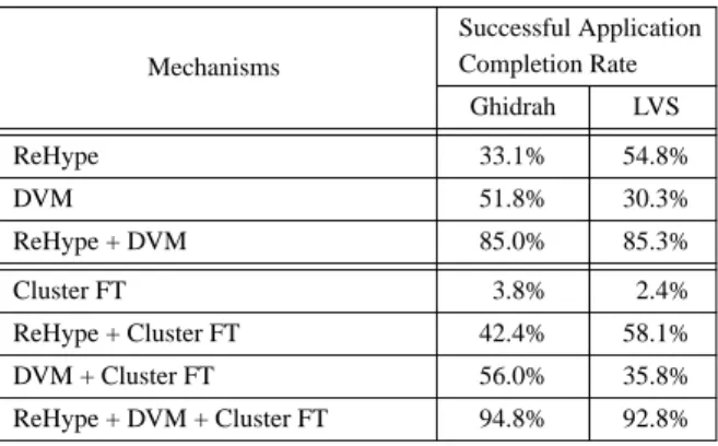
Table 6 shows the different combinations of VI and cluster fault tolerance mechanisms and the resulting successful application completion rates for both Ghidrah and LVS. The first two rows show the success rates when a single VI fault tolerance mechanism is used while the third row shows the success rates when both VI fault tolerance mechanisms are used together. These results assume no fault tolerance mechanisms in the cluster middleware. Table 6, in the context of Table 5, reflects the fact that the benefit of a single VI fault-tolerance mechanism is limited by the fraction of CPU time spent executing the component protected by that mechanism.
As shown in Table 6, utilizing just VI fault tolerance mechanisms, for a fault in the VI that is manifested as an error, the system achieves a successful application completion rate
Table 6. Contribution of different fault tolerance mechanisms to the successful application completion rate. Percentage of correct application operation out of manifested faults in VI.
Successful Application Completion Rate Ghidrah LVS Mechanisms 33.1% 54.8% ReHype 51.8% 30.3% DVM 85.0% 85.3% ReHype + DVM 3.8% 2.4% Cluster FT 42.4% 58.1% ReHype + Cluster FT 56.0% 35.8% DVM + Cluster FT 94.8% 92.8% ReHype + DVM + Cluster FT
of over 85%. Based on this resilient VI, existing cluster fault tolerance mechanisms can be leveraged to further increase the probability of correct system operations. The last four rows in Table 6 show the success rate of Ghidrah and LVS given different combinations of VI and cluster fault tolerance mechanisms. With only fault tolerance in the cluster middleware, system failure is almost guaranteed given a manifested fault in the VI. However, the cluster fault tolerance techniques significantly improve system reliability compared with using VI mechanisms alone. Specifically, success rates for the combinations of mechanisms exceed the sum of the success rates of the individual mechanisms. This is due to scenarios such as a VMM recovery using ReHype resulting in an AppVM failure which is then handled by the cluster fault tolerance mechanisms. It should be noted that, regardless of any VI fault tolerance mechanisms, the cluster fault tolerance mechanisms are needed to ensure the correct operations of the cluster despite faults in AppVMs.
5.4. Resiliency of the Virtual Cluster
To evaluate the resiliency of the virtual cluster, we begin with the assumption that the cluster middleware ensures that the system is 100% reliable when deployed on a physical cluster. Thus, if a single fault is injected into the system randomly in time and space, the probability that the result will be a system failure is determined by: the fraction of time the CPUs spend executing code of the VI, the probability that a fault in the VI is manifested as a failure of a system component, and the probability that a component failure results in a system failure. As shown in Table 6, the probabilities of system failure due to a manifested fault in the VI, for Ghidrah and LVS, are 5.2% and 7.2%, respectively. Table 5 shows that, excluding the cycles spent executing the PrivVM, the fractions of CPU cycles spent executing VI code are 15.0% and 15.7%, respectively. Hence, if every fault in the VI results in a component failure (is manifested), the probabilities of system failure due to a random fault anywhere in the system are 0.8% and 1.1%, respectively. Howev er, in our experiments, only
25% of faults in the VI manifest as component failures. Taking this into account, the probabilities that a random fault anywhere in the system will lead to system failure are approximately 0.2% and 0.28%, respectively. Furthermore, if we consider the fact that CPUs are typically not utilized 100% of the time (30.5% and 27.7%, respectively with our workload, as shown in Table 5), for Ghidrah and LVS, the probabilities of system failure due to a random fault are approximately 0.06% and 0.08%, respectively.
The results presented so far ignore failures that can occur in the PrivVM. We hav e not yet implemented any mechanism for tolerating such failures. Hence, for now, the only way to take PrivVM failures into account is to assume that all such failures lead to system failure. Hence, based on Tables 5 and 6, the probabilities of system failure due to a manifested fault in the VI, for Ghidrah and LVS, are 7.7% and 11.4%, respectively. The fractions of cycles spent executing VI code are 15.3% and 16.3%, respectively (Table 5). We assume that faults in the PrivVM are manifested as component failures at the same rate (0.25) as in other VI components and that the overall CPU utilization rates are the same (30.5% and 27.7%, respectively). Hence, for Ghidrah and LVS, the probabilities of system failure due to a random fault anywhere in the system are approximately 0.09% and 0.13%, respectively.
6. Related Work
Over the last few years there has been significant interest in techniques for enhancing system resiliency to device driver failure [6, 17, 10, 15, 12]. These techniques isolate device drivers in a DVM and recover the failed device driver by rebooting the DVM or using a new device driver in a spare DVM. The work reported in this paper, includes a mechanism that has not been evaluated previously — enabling the use of software RAID to recover from DVM failures.
The ReHype mechanism for recovery from VMM failure using microreboot was introduced in [16], and is used in this paper. The ReHype mechanism built upon the Otherworld [5] mechanism for microrebooting the Linux kernel while preserving process states, and the RootHammer [13] mechanism for rejuvenating the Xen hypervisor and PrivVM through a microreboot while preserving VM states.
None of the previous works have evaluated how different VI resiliency enhancement mechanisms work together. The previous works have also not presented nor evaluated the idea of leveraging existing cluster computing technology together with virtualization using resiliency-enhanced VI to deploy highly-reliable systems on modern hardware.
There has been extensive research in the area of reliable cluster computing [3, 26, 18, 8, 30, 9]. These and many other works rely on the fact that different physical nodes usually fail independently of one another. Hence, proposed mechanisms can tolerate only a limited number of failed nodes (typically, one). Our results facilitate leveraging all of these works.
Recent works on virtual clusters for high performance computing leveraged system-level virtualization to implement checkpointing of VM state for rollback recovery and for proactive migration of virtual cluster nodes away from potentially faulty computers [22, 29, 24]. Since these works use virtualization for HPC applications, they motivate the importance of VI resiliency even when there is no need for server consolidation used for increased utilization.
7. Summary and Conclusions
Virtual clusters are inherently less reliable than physical clusters because a single fault in the VI can cause multiple virtual cluster nodes to fail. We hav e described and evaluated enhancements to the VI that allow the VI to survive most manifestations of faults in the VI. The resulting resilient VI was used to deploy virtual clusters running two different cluster workloads: Ghidrah, a fault-tolerant middleware supporting compute-intensive applications, and the Linux Virtual Server (LVS) middleware supporting highly-available web services. Fault injection was used to evaluate the effectiveness of the VI resiliency enhancements.
We hav e shown that, with proper enhancements to the VI, for approximately 92% of faults in the VI that are manifested as component failures, a virtual cluster is able to maintain correct system operation. Based on the experimental results, a rough estimate of the probability that a random fault in the virtual cluster results in system failure, is 0.3%. Thus, the virtual cluster with resilient VI is a viable platform for running cluster workloads that require high reliability.
Acknowledgements
This work is supported, in part, by a donation from the Xerox Foundation University Affairs Committee.
References
[1] D. H. Bailey, E. Barszcz, J. T. Barton, D. S. Browning, R. L. Carter, L. Dagum, R. A. Fatoohi, P. O. Frederickson, T. A. Lasinski, R. S. Schreiber, H. D. Simon, H. D. Simon, V. Venkatakrishnan, and S. K. Weeratunga, ‘‘The NAS Parallel Benchmarks,’’ Int. Journal of High
Performance Computing Applications 5(3), pp. 63-73 (September
1991).
[2] P. Barham, B. Dragovic, K. Fraser, S. Hand, T. Harris, A. Ho, R. Neugebauer, I. Pratt, and A. Warfield, ‘‘Xen and the Art of Virtualization,’’ 19th ACM Symp. on Operating Systems Principles, Bolton Landing, NY, pp. 164-177 (October 2003).
[3] K. P. Birman, ‘‘The Process Group Approach to Reliable Distributed Computing,’’ Communications of the ACM 36(12), p. 37 (December 1993).
[4] J. P. Casazza, M. Greenfield, and K. Shi, ‘‘Redefining Server Performance Characterization for Virtualization Benchmarking,’’ Intel
Technology Journal 10(3), pp. 243-251 (August 2006).
[5] A. Depoutovitch and M. Stumm, ‘‘Otherworld - Giving Applications a Chance to Survive OS Kernel Crashes,’’ 5th ACM European Conf. on
Computer Systems, Paris, France, pp. 181-194 (April 2010).
[6] K. Fraser, S. Hand, R. Neugebauer, I. Pratt, A. Warfield, and M. Williamson, ‘‘Safe Hardware Access with the Xen Virtual Machine Monitor,’’ 1st Workshop on Operating System and Architectural Support
for the on demand IT InfraStructure (OASIS) (ASPLOS) (October 2004).
[7] J. Gray, ‘‘Why Do Computers Stop and What Can Be Done About It?,’’
5th Symp. on Reliability in Distributed Software and Database Systems,
Los Angeles, CA, pp. 3-12 (January 1986).
[8] I. Haddad, C. Leangsuksun, and S. L. Scott, ‘‘HA-OSCAR: The Birth of Highly Available OSCAR,’’ Linux Journal(115) (November 2003). [9] P. H. Hargrove and J. C. Duell, ‘‘Berkeley Lab Checkpoint/Restart
(BLCR) for Linux Clusters,’’ Journal of Physics: Conference Series
46(1), pp. 494-499 (2006).
[10] J. N. Herder, H. Bos, B. Gras, P. Homburg, and A. S. Tanenbaum, ‘‘Fault Isolation for Device Drivers,’’ Int. Conf. on Dependable Systems
and Networks, Estoril, Lisbon, Portugal, p. xx (June 2009).
[11] I. Hsu, A. Gallagher, M. Le, and Y. Tamir, ‘‘Using Virtualization to Validate Fault-Tolerant Distributed Systems,’’ Int. Conf. on Parallel and
Distributed Computing and Systems, Marina del Rey, CA, pp. 210-217
(November 2010).
[12] H. Jo, H. Kim, J.-W. Jang, J. Lee, and S. Maeng, ‘‘Transparent Fault Tolerance of Device Drivers for Virtual Machines,’’ IEEE Transactions
on Computers 59(11), pp. 1466-1479 (November 2010).
[13] K. Kourai and S. Chiba, ‘‘A Fast Rejuvenation Technique for Server Consolidation with Virtual Machines,’’ Int. Conf. on Dependable
Systems and Networks, Edinburgh, UK, pp. 245-255 (June 2007).
[14] M. Le, A. Gallagher, and Y. Tamir, ‘‘Challenges and Opportunities with Fault Injection in Virtualized Systems,’’ 1st Int. Workshop on
Virtualization Performance: Analysis, Characterization, and Tools,
Austin, TX (April 2008).
[15] M. Le, A. Gallagher, Y. Tamir, and Y. Turner, ‘‘Maintaining Network QoS Across NIC Device Driver Failures Using Virtualization,’’ 8th
IEEE Int. Symp. on Network Computing and Applications, Cambridge,
MA, pp. 195-202 (July 2009).
[16] M. Le and Y. Tamir, ‘‘ReHype: Enabling VM Survival Across Hypervisor Failures,’’ 7th ACM Int. Conf. on Virtual Execution
Environments, Newport Beach, CA, pp. 63-74 (March 2011).
[17] J. LeVasseur, V. Uhlig, J. Stoess, and S. Gotz, ‘‘Unmodified Device Driver Reuse and Improved System Dependability via Virtual Machines,’’ 6th Symp. on Operating Systems Design & Implementation, San Francisco, CA, pp. 17-30 (December 2004).
[18] M. Li, D. Goldberg, W. Tao, and Y. Tamir, ‘‘Fault-Tolerant Cluster Management for Reliable High-Performance Computing,’’ Int. Conf. on
Parallel and Distributed Computing and Systems, Anaheim, CA,
pp. 480-485 (August 2001).
[19] M. Li, W. Tao, D. Goldberg, I. Hsu, and Y. Tamir, ‘‘Design and Validation of Portable Communication Infrastructure for Fault-Tolerant Cluster Middleware,’’ IEEE Int. Conf. on Cluster Computing, Chicago, IL, pp. 266-274 (September 2002).
[20] Linux Virtual Server, http://linuxvirtualserver.org.
[21] A. Menon, J. R. Santos, Y. Turner, G. J. Janakiraman, and W. Zwaenepoel, ‘‘Diagnosing Performance Overheads in the Xen Virtual Machine Environment,’’ 1st ACM/USENIX Conf. on Virtual Execution
Environments, Chicago, IL, pp. 13-23 (June 2005).
[22] M. F. Mergen, V. Uhlig, O. Krieger, and J. Xenidis, ‘‘Virtualization for High-Performance Computing,’’ ACM SIGOPS Operating Systems
Review 40(2), pp. 8-11 (April 2006).
[23] Microsoft, Hyper-V Architecture, http://msdn.microsoft.com/en-us/
library/cc768520.aspx.
[24] A. B. Nagarajan, F. Mueller, C. Engelmann, and S. L. Scott, ‘‘Proactive Fault Tolerance for HPC with Xen Virtualization,’’ 21st Int. Conf. on
Supercomputing, pp. 23-32 (2007).
[25] J. R. Okajima, ‘‘aufs—another unionfs,’’ http://aufs.sourceforge.net/
aufs.html.
[26] D. Powell, ‘‘Distributed Fault Tolerance—Lessons Learnt from Delta-4,’’ Lecture Notes in Computer Science 774, pp. 199-217 (1994). [27] H. V. Ramasamy and M. Schunter, ‘‘Architecting Dependable Systems
Using Virtualization,’’ Workshop on Architecting Dependable Systems, Edinburgh, UK (June 2007).
[28] M. Rosenblum and T. Garfinkel, ‘‘Virtual Machine Monitors: Current Technology and Future Trends,’’ IEEE Computer 38(5), pp. 39-47 (May 2005).
[29] L. Youseff, R. Wolski, B. Gorda, and C. Krintz, ‘‘Evaluating the Performance Impact of Xen on MPI and Process Execution for HPC Systems,’’ 2nd Int. Workshop on Virtualization Technology in
Distributed Computing (2006).
[30] W. Zhang and W. Zhang, ‘‘Linux Virtual Server Clusters,’’ Linux