TABLE OF CONTENTS
TABLE OF FIGURES ... 5
EXECUTIVE SUMMARY ... 7
1 BACKGROUND ... 9
1.1 MOBILE APPLICATION LANDSCAPE ... 9
1.2 MOBILE NETWORK ARCHITECTURE ... 10
1.3 INTRODUCTION OF UMTS AND LTE NETWORK ARCHITECTURE ... 11
1.3.1 LTE ... 13
1.3.2 Offloading Architectures ... 15
1.4 ACTIVITY STATES ON WIRELESS ... 18
1.4.1 The UMTS State Machine ... 18
1.4.2 The LTE State Machine ... 21
1.4.3 Interaction Between UMTS and LTE ... 22
1.5 QOS FOR APPLICATIONS, POLICY & CHARGING ... 22
1.5.1 UMTS QoS ... 23
1.5.2 LTE QoS ... 24
1.5.3 QoS Management and Policy Framework ... 26
1.6 DEVICE PLATFORMS ... 27 1.6.1 iOS ... 28 1.6.2 Android ... 29 1.6.3 Windows Phone... 29 1.6.4 Blackberry OS ... 30 2 PROBLEM DEFINITION ... 31
2.1 IMPACT OF APPLICATION BEHAVIOR ... 31
2.2 IMPACT OF DEVICE PLATFORM BEHAVIOR ... 33
2.2.1 Control Plane Impact ... 33
2.3.1 Security Risks Associated with Smartphone ... 38
2.3.2 Malware Propagation ... 38
2.3.3 Bad Packet Injection ... 38
2.4 TRENDS IN NETWORK ... 39
2.4.1 Assessment of Subscribers and Applications ... 40
2.4.2 Machine to Machine (M2M) Contributions to Traffic Growth ... 43
2.4.3 Application to Historical and Current Data Traffic ... 44
3 RECOMMENDATIONS ... 47
3.1 ADDRESSING IMPACT OF APPLICATION AND DEVICE PLATFORM BEHAVIOR ... 47
3.1.1 HeartBeat for Always-on Application ... 47
3.1.2 Constant Push Service ... 47
3.1.3 Network Attachment ... 47
3.2 ENHANCEMENTS TO NETWORK ARCHITECTURE ... 48
3.2.1 Service Delivery Environments ... 48
3.2.2 Subscriber and Service Aware Traffic Management ... 50
3.2.3 Network Optimization ... 50
3.2.4 Data Caching in Network ... 51
3.2.5 Virtualization ... 51
3.2.6 Service-Level Analytics tools ... 51
3.2.7 Traffic Offloading ... 52
3.3 ENHANCEMENTS FOR CLIENT DEVICE APPLICATION PLATFORMS ... 53
3.3.1 Efficient Use of Radio Resources ... 53
3.3.2 Application Platform Support for Network Capabilities ... 57
3.3.3 Application Quality Assurance ... 57
3.4 GUIDELINES FOR APPLICATION DEVELOPMENT ... 58
3.4.1 Asynchronous Request and Responses ... 58
3.4.2 Saving Data and Session Information ... 59
3.4.4 Network Technology Awareness ... 60
3.4.5 Lengthening Data Bursts ... 60
3.4.6 Queueing up Data ... 61
3.4.7 Retry Scheduling ... 61
3.4.8 Text Compression and Media Transcoding ... 62
3.5 ENHANCEMENTS WITH RESPECT TO SECURITY ... 62
3.5.1 Malware Defenses ... 62
3.5.2 Packet Filtering ... 64
3.6 END USER BEHAVIOR ... 66
3.6.1 Increasing Awareness ... 66
3.6.2 Incentives for Reducing Data Use ... 67
3.6.3 Equipping Users for Effective Usage Management ... 67
4 CONCLUSIONS ... 68
5 REFERENCES ... 69
TABLE OF FIGURES
Figure 1: Separation of Service and Connectivity Layers ... 10
Figure 2: HSPA/LTE Network Elements & Architecture ... 13
Figure 3: LTE/EPC Network Functional Architecture ... 15
Figure 4: Femtocell Architecture ... 16
Figure 5: Wi-Fi Offload architecture ... 17
Figure 6: The UMTS state machine (without URA_PCH or Cell PCH activated) ... 19
Figure 7: The UMTS state machine URA_PCH or Cell PCH activated ... 20
Figure 8: LTE State Machine has only two main states ... 21
Figure 9: Interaction between UMTS and LTE state machines (derived from 3GPP 36.331) ... 22
Figure 10: UMTS QoS architecture ... 23
Figure 11: Weekly application traffic for different subscriber clusters of a new Android smartphone model (high-end with large screen) at one specific operator (Source: Ericsson Traffic And Market Data Report Nov 2011) ... 31
Figure 12: Traffic Mix for data plans (Source: Ericsson Traffic And Market Data Report Nov 2011) ... 32
Figure 13: Global Sales of Devices by Type (in Millions) (Source: Strategy Analytics& ABI Research) .... 33
Figure 14: Device-triggered Fast dormancy increases state changes and signaling when PCH state not is used ... 34
Figure 15: Signaling traffic generated by Apps ... 35
Figure 16: Push Service towards devices ... 36
Figure 17: Data Forecast from Cisco ... 37
Figure 18: Bad packet injection ... 39
Figure 19: Unconstrained growth in demand assuming 100% mainstream acceptance of leader behaviors. (This is an upper bound on the traffic forecast.) ... 42
Figure 20: Crossing the Chasm estimate of the demand curve without caps or Wi-Fi offload. ... 42
Figure 21: US Daily Traffic forecast with and without expected Wi-Fi Offload included. ... 43
Figure 22: Average downlink data volume per subscriber versus device release date. From Michael Flanagan ©2012 by Arieso Inc., used with permission ... 45
Figure 23: Fitting curves to various historical data in Cisco’s VNI forecast. ... 46
Figure 25: for EUTRAN/EPC macro network (Fig. 5.6.3.2 in TS 23.829) ... 53
Figure 26: Fast dormancy functionality ... 54
Figure 27: Key LTE Radio Access Features ... 55
Figure 28: UE/device states on LTE ... 56
Figure 29: High level overview of caching between device and application server ... 60
Figure 30: Comparison of signaling, time taken for small bursts and large bursts ... 61
Figure 31: Network Protection Architecture - Firewalls and IDP ... 63
EXECUTIVE SUMMARY
Mass market mobile wireless applications and devices for the subscribers have exploded in recent years. The proliferation of new applications, devices and services has led to increased signaling and data traffic flowing through HSPA and LTE mobile broadband networks.
This white paper researches, analyzes and discusses some of the deeper aspects of addressing the increased load on HSPA and LTE mobile broadband networks due to the new types of traffic and increased Internet access on wireless. This includes identifying requirements on most parts of the ecosystem generating the traffic and making recommendations to help mitigate the effects of new devices and services.
o Section 1 of the paper sets the background and describes network architectures and principles. This section also introduces the reader to concepts and stakeholders identified later in the paper like QoS, device platforms and operating systems that influence network traffic.
o Section 2 provides the problem definition and introduces the reader to the effects that applications, devices and user behavior have on network traffic load. With the moving of primary Internet access from fixed to mobile devices, the changes to mobile device and infrastructure are also discussed.
o Section 3 builds up the previous sections to identify short term and longer term recommendations to address the growing mobile signaling and data traffic due to the explosion of devices and applications. These recommendations address stakeholders in the entire ecosystem, including application developers, mobile OS vendors, security on the mobile Internet, content providers and consumers, end users, etc.
The paper identifies some of the following challenges affecting network performance and end user experience:
Impact of device platform behavior in both the control plane (always-on, constant push) and the user plane.
New trends in device security arising from smartphone OS risks like malware. Impacts from Network trends like streaming, computing, storing, gaming, video. Recommendations are made in some of the following areas:
Enhancements to network architecture including optimizing service delivery environments, traffic management, and traffic offload solutions.
Enhancements to device architecture to allow for optimization in radio resources, and network awareness.
Guidelines for application development that consider the challenges of wireless access, caching, scheduling.
Enhancements to address device security including Firewalls, intrusion detection, packet filtering etc.
Education of end users in the areas of awareness of data/signaling usage, choice of appropriate access for heavy data usage, support for app data usage alerts etc.
Finally, some key conclusions of the paper include the following:
Capacity for mobile broadband must continue to increase as new technologies and powerful devices that support bursty and chatty applications and drain network resources enter the market. Efficient use of radio resources through innovations for traffic offloading and the use of the best
available access such as Wi-Fi, femtocells and picocells should be considered.
Collaboration between network providers, application providers and device manufacturers is essential to address capacity needs and end user expectations. Improvements could be made to application design, device platforms and feature activations.
1 BACKGROUND
1.1 MOBILE APPLICATION LANDSCAPE
The rollout of high-speed wireless networks and devices was accompanied by the development of Wireless Access Protocol (WAP) browsers and device application platforms such as J2ME and Windows Mobile. Over time, networks have matured in capabilities and devices now feature larger, higher resolution screens and more powerful processors. This increased capability of the network and device hardware has motivated the development of robust software platforms incorporating HyperText Markup Language (HTML) browsers, comprehensive email clients and rich application platforms as exemplified by the iPhone, Android, BlackBerry, Windows Mobile, Symbian and WebOS smartphone platforms. The advent of full HTML browsers on smartphones has made ubiquitous access to the web feasible and the development of WAP sites typically unnecessary. In addition, ubiquitous access to email has had a tremendous impact on productivity and has become an essential part of business. Typically most smartphone platforms today ship with integrated browsers and email clients that are optimized by the platform developer for both network utilization and user experience.
However, another big change in the use of mobile devices over the last few years has been the proliferation of applications or “apps” as they are most commonly known. These mobile applications offer convenient access to services through a rich user experience and are often free or have a minimal price tag. Further, the universal availability of application development environments from the application platform vendors and the ready availability of a distribution channel in the form of application stores have enabled the rapid development of the mobile application ecosystem driving significant use of mobile networks and a complementary impact on the use of mobile web browsing and mobile email usage as well.
Looking ahead, the next major step in the evolution of mobile applications is the transformation of voice and video calling into a mobile data application with the replacement of circuit switched voice and video calling by packet switched calling in next-generation networks. Further, as mobile browsers implement the full suite of HTML5 technologies, features characteristic of applications such as data persistence, native code execution and multi-tasking will become available to web sites/browser-based applications, effectively blurring the differences between browser-based applications and native applications. Another emerging trend is the use of always-on connectivity in conjunction with multi-tasking application environments to implement rich messaging services.
Driving the mobile application usage explosion has been the ready availability of a wide choice of innovative applications. These mobile applications are developed, delivered and monetized using mobile application platforms, which feature centralized stores or marketplaces for application distribution and billing integration to enable monetization. The mobile application platform consists of an operating system, application framework and key applications. A developer uses a Software Development Kit (SDK) corresponding to the mobile application platform, which gives them access to the necessary tools and Application Programming Interface (APIs) necessary to develop applications on the platform. The application framework enables reuse of components thereby enabling developers to build rich and innovative applications rapidly. In addition, the application framework enables developers to utilize features of the device hardware, access location information and run background services. Developers distribute their applications by submitting them to the application marketplaces where the marketplace operator may verify them before they are offered to end users. Further, the application marketplaces include review and rating mechanism for end users to provide feedback. These marketplace
operator-driven and end user-operator-driven quality assurance mechanisms play a key role in the efficient operation of these marketplaces and the applications available through them. These mobile application marketplaces are operated by device manufacturers, service providers, mobile application platform vendors and other third parties.
The widespread uptake of smartphones, ready availability of application development platforms and distribution marketplaces are fostering innovation in applications on an unprecedented scale leading to an explosion in the number of applications, the usage of the applications and, naturally, the usage of mobile data networks.
1.2 MOBILE NETWORK ARCHITECTURE
Mobile networks are comprised of a number of network elements integrated to address the over-the-air communication over radio, the transport of data between the radio terminations and the Internet, the setup of communication sessions and enablement of services utilizing the data connectivity.
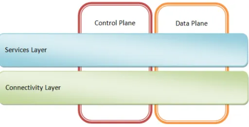
Figure 1: Separation of Service and Connectivity Layers
As shown in Figure 1, the elements of the network are:
Control or Signaling plane: Enable the initiation and termination of communication sessions. Data plane: The elements of the network that enable the transport of the communication data
over sessions, previously established using the Control or Signaling plane.
Connectivity layer: Provides end-to-end data communication that may vary based on the type of session. For example, packet connectivity in HSPA does not involve the MSC, VLR; circuit switched voice in HSPA does not involve the SGSN, GGSN.
Services layer: Translates the data communicated in the Connectivity layer into services. This is the abstracted functionality that utilizes the Connectivity layer to implement end-user friendly services.
The interaction between the Connectivity and Services layers is a focus area in this white paper. These would include APIs at the network level for communication with the Connectivity layer, and APIs at the device for the services/apps on the device to communicate with the Connectivity layer on the device. Connectivity layer technologies in the Data plane include channel modulation, error correction algorithms and packet routing in conjunction with Authentication, Authorization and Accounting (AAA) and Quality of Service (QoS) elements in the network. Connectivity layer technologies in the Control plane include multiple access, duplexing and paging.
Service layer technologies in the Data plane include user level functionality such as voice, web browsing, videos, etc. with their own unique connectivity, content and interactivity requirements. Service layer technologies in the Control plane include Notification services for Application to Person (A2P) messaging. The elements of the Service layer both in the Data and Control planes are typically made available to mobile application developers using standard software and web development abstraction paradigms such as networking protocols, sockets, markup languages, etc. Connectivity layer technologies in the Data and Control planes are typically reserved for management by the service providers.
The separation of the technologies employed across the mobile network into Connectivity and Service layers enables services to be developed independent of the underlying Connectivity layer technologies. Further, the layering enables mobile application developers to utilize the mobile network using paradigms familiar to them.
However, the limitations and capabilities of the Connectivity layer are not completely eliminated by the layering and an awareness of the underlying Connectivity layer in the Service layer enables improved performance of the total system and cross-layer optimization is the motivation for this paper.
Further, the availability of mature application or service development platforms both on client devices and in the cloud is triggering an exponential increase in the number of applications available on mobile networks. Although network operators continue to provide services within their domain, the subscribers are increasingly accessing the Internet for services as well. The Internet services encompass communication (email, VoIP, instant messaging), entertainment, social networking, navigation or other services. The growing trend is for many of these new services being developed to be delivered by application developers using platforms that are located entirely outside of the mobile network bringing with them unprecedented challenges for the Service providers. These challenges include a reduced ability to control the kinds of applications that make use of a network’s resources.
1.3 INTRODUCTION OF UMTS AND LTE NETWORK ARCHITECTURE
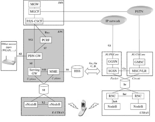
Universal Mobile Telecommunications System (UMTS) is a member of the family of third-generation systems defined by 3GPP, which combines innovations in radio access as an evolution from GSM. This is a new service architecture, which allows for mobile-fixed convergence at the service and application level. This network architecture is evolved into Long Term Evolution (LTE) networks, which bring efficiencies in the areas of latency, data rates and network architecture. See Figure 2.
UMTS:
The system architecture of an UMTS network can be divided in two broad interacting domains: UMTS Terrestrial Radio Access Network (UTRAN) and the Core Network (CN).
The UTRAN consists of the Radio Base Station (NodeB) and the Radio Network Controller (RNC). Wideband CDMA technology was selected for the UTRAN air interface.
The main function of the CN is to provide switching, routing and transit for user traffic. The CN also contains the databases and network management functions. The UMTS CN is divided in circuit switched and packet switched domains. Some of the UMTS circuit switched elements are the Mobile services Switching Centre (MSC), Visitor location register (VLR) and Gateway MSC. UMTS Packet switched elements are Serving GPRS Support Node (SGSN) and Gateway GPRS Support Node (GGSN).
LTE:
The system architecture of an LTE network can be divided in two broad interacting domains: enhanced UMTS Terrestrial Radio Access Network (eUTRAN) and the Enhanced Packet Core (EPC).
The eUTRAN consists of the enhanced Radio Base Station (eNodeB). Orthogonal Frequency Division Multiplexing (OFDM) technology was selected for the eUTRAN air interface in the downlink and SC-FDMA (a CDMA technology) in the uplink.
The main function of the CN is to provide switching, routing and transit for user traffic. The CN also contains the databases and network management functions. The EPC consists only of a packet switched domain, with some common components from IP Multimedia Systems (IMS). EPC Packet switched elements are Mobility Management Entity (MME) and PDN gateway (PGW) and Serving Gateway (SGW).
Figure 2: HSPA/LTE Network Elements & Architecture
For EPC, 3GPP (Third Generation Partnership Project) defines nodes common to EPC and IMS that will function in the different releases for future technologies. The Home subscriber server (HSS) acts for user control, and the Policy Control and Resource Functions (PCRF) specify access policies.
1.3.1 LTE
LTE describes standardization work by the 3GPP to define a new high-speed radio access method for mobile communications systems. This specification is standardized in 3GPP Release 8 (Rel-8). In this architecture, the main task is continuing with the smooth transition from 3G networks. LTE offers a smooth evolutionary path to higher speeds and lower latency. Coupled with more efficient use of operators’ finite spectrum assets, LTE enables an even richer, more compelling mobile service environment.
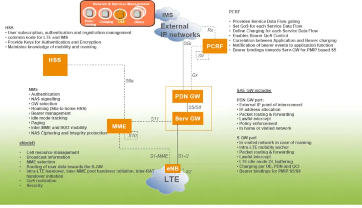
In order to achieve this, LTE networks (See Figure 3) offer enhanced: Spectrum efficiency
Support for variable bandwidth
Backward compatibility with pre-Rel 8 3GPP Releases
Interfaces to interoperate with non 3GPP accesses e.g. CDMA and Wi-Fi accesses
One of the most significant features of LTE and EPC is its transition to a flat, all-IP based core network with a simplified architecture and open interfaces. Indeed, much of 3GPP’s standardization work targets the conversion of existing core network architecture to an all-IP system. Within 3GPP, this initiative is called Evolved Packet Core (EPC) and was formerly known as System Architecture Evolution (SAE). EPC enables more flexible service provisioning plus simplified interworking with fixed and non-3GPP mobile networks.
Flatter network architecture in the EPC leads to improved data latency and better support of delay sensitive, interactive and real-time communications. EPC is based on IP protocols with support for TCP/IP, UDP, Diameter, SIP, etc. This allows operators to offer IP-based voice, video, rich media and messaging. This migration to all-packet architecture also enables improved interworking with existing fixed and wireless communication networks.
There are two nodes in the EPC architecture user plane; the LTE base station (eNodeB) and the EPC Gateway, as shown in Figure 3. This flat architecture reduces the number of involved nodes in the connections. The LTE base stations are connected to the core network over the S1 interface. Existing 3GPP (GSM and WCDMA/HSPA) and 3GPP2 (CDMA) systems are integrated to the evolved system through standardized interfaces, providing optimized mobility with LTE. For 3GPP systems, this means a signaling interface between the Serving GPRS Support Node (SGSN) and the evolved core network. For 3GPP2, a signaling interface between CDMA RAN and evolved core network addresses mobility.
Control signaling is handled by the Mobility Management Entity (MME) node, separate from the gateway, facilitating optimized network deployments and enabling fully flexible capacity scaling.
Figure 3: LTE/EPC Network Functional Architecture
1.3.2 OFFLOADING ARCHITECTURES
Due to increases in smartphone usage and their high impact on 3GPP networks, analysis for new options to manage data traffic is a critical issue for mobile operators. Throughout the world and especially in the Americas region, there is a significant lack of spectrum.
Mobile data offloading is the use of complementary network technologies for delivering data originally targeted for cellular networks. Rules triggering the mobile offloading action can either be set by an end user (mobile subscriber) or an operator. The decision on choice of network usually resides in an end-user device, in a server or it is divided between the two. For the end-users, the purpose for doing mobile data offloading is based on data service cost control and availability of higher bandwidth. For the operators, the main purpose for the offloading is congestion of the cellular networks. The main complementary network technologies used for the mobile data offloading are Wi-Fi and femtocell.
1.3.2.1 FEMTOCELLS
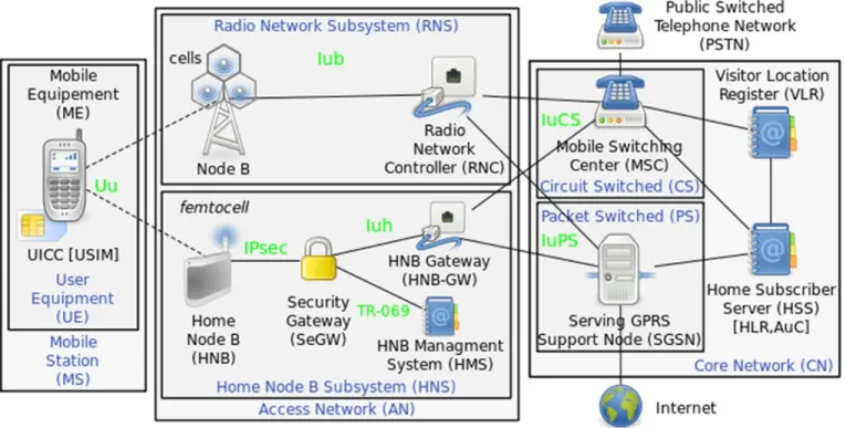
A femtocell is a small cellular base station, typically designed for use in a home or small business. It connects to the service provider’s network via broadband (such as DSL or cable); current designs typically support two to four active mobile phones in a residential setting, and eight to 16 active mobile phones in enterprise settings. A femtocell allows service providers to extend service coverage indoors, especially where access would otherwise be limited or unavailable. Although much attention is currently focused on WCDMA, the concept is applicable to all standards, including GSM, CDMA2000, TD-SCDMA, WiMAX and LTE solutions.
For a mobile operator, the attractions of a femtocell are improvements to both coverage and capacity, especially indoors. Consumers benefit from improved coverage and potentially better voice quality and battery life. Depending on the carrier they may also be offered more attractive tariffs (e.g. discounted calls from home).
A femtocell-based deployment will work with existing handsets but requires installation of a new access point that uses licensed spectrum. In 3GPP terminology, a Home NodeB (HNB) is a WCDMA femtocell. A Home eNodeB (HeNB) is an LTE femtocell.
Typically the range of a microcell is less than two kilometers wide, a picocell is 200 meters or less, and a femtocell is on the order of 10 meters.
Figure 4: Femtocell Architecture
1.3.2.2 WI-FI OFFLOAD
Most data capable devices and smartphones now come with built in Wi-Fi capability. There are already thousands of installed Wi-Fi networks mainly in congested areas such as airports, hotels and city centers and the number is growing rapidly. One of the main concerns in a converged Wi-Fi/cellular network is to have a seamless and consistent user experience for subscribers. Wi-Fi offloading is an emerging approach to data offloading with multiple solutions entering to the market with using different capabilities in UE, external clients and SIM.
Standardization efforts have focused on specifying tight or loose coupling between the cellular and the Wi-Fi networks. 3GPP based Enhanced Generic Access Network (EGAN) architecture applies tight coupling as it specifies rerouting of cellular network signaling through Wi-Fi access networks. This makes
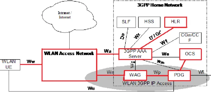
3GPP has also specified an alternative loosely coupled solution for Wi-Fi. The approach is called Interworking Wireless LAN (IWLAN) architecture and it is a solution to transfer IP data between a mobile device and operator’s core network through a Wi-Fi access. In this approach the two networks are in practice totally separated and network selection is done by a client application. In the IWLAN architecture, a mobile device opens a VPN/IPSec tunnel from the device to the dedicated IWLAN server in the operator’s core network to provide the user either an access to the operator’s walled-garden services or to a gateway to the public Internet. With loose coupling between the networks, the only integration and interworking point is authentication by an AAA connected to the HLR in the mobile network.
Very few terminals in the market handle IPSec connectivity in a native way today. Therefore, the UE needs an external client to support this functionality. The impact of installing this client and its behavior is a concern for new implementations.
The most straightforward way to offload data to the Wi-Fi networks is to have a direct connection to the public Internet. This no coupling alternative omits the need for interworking standardization. For the majority of the web traffic there is no added value to route the data through the operator core network. In this case the offloading can simply be carried out by switching the IP traffic to use the Wi-Fi connection in mobile client instead of the cellular data connection. In this approach the two networks are in practice totally separate and network selection is done by a client application.
Access Network Discovery and Selection Function (ANDSF) is the most complete 3GPP approach to date for controlling offloading between 3GPP and non-3GPP access networks (such as Wi-Fi). The purpose of the ANDSF is to assist user devices in discovering access networks in their vicinity and to provide rules (policies) to prioritize and manage connections to all networks.
Figure 5: Wi-Fi Offload architecture
With this final architecture, all policies and control defined by the mobile operator will be applied following business rules, and by the other side, all sessions will be handled by the same packet core providing continuity even if the user change his access from Wi-Fi to 3GPP networks and vice versa.
There are three main initiation schemes for mobile offload to Wi-Fi: WLAN scanning initiation, user initiation and remotely managed initiation.
1. In the WLAN scanning based initiation the user device performs periodically WLAN scanning. When a known or an open Wi-Fi network is found an offloading procedure is initiated.
2. In the user initiated mode a user is prompted to select which network technology is used. This happens usually once per network access session.
3. In the remotely managed approach, a network server initiates each offloading procedure by prompting the connection manager of a specific user device. Operator managed is a subclass of the remotely managed approach.
o In the operator managed approach, an operator is monitoring its network load and user behavior. In the case of the forthcoming network congestion the operator initiates the offloading procedure.
1.4 ACTIVITY STATES ON WIRELESS
As the rapidly surging growth of smart phones in wireless networks, various types of applications including those “always-on” applications contribute as significant factors of consumption of UE power, bandwidth and network resources. Messages are sent between the phone’s active applications and their respective servers in the Internet, causing the phone to more frequently needing to connect/reconnect to the network, and subsequently moving between different states of the wireless state machine. The more frequent connections the phone needs with the network, the more it consumes battery, and the more frequent state changes between active and energy saving states, the more radio network management messages are needed, leading to increased signaling traffic in the network.
1.4.1 THE UMTS STATE MACHINE
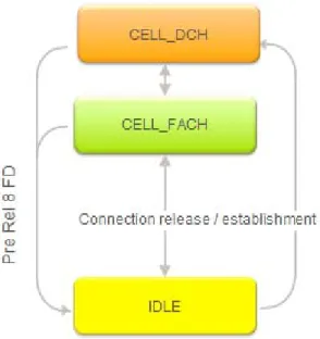
In UMTS, the UE states supported are IDLE, CELL_FACH, URA_PCH, Cell_PCH and CELL_DCH. The last four states are for the UE in Connected Mode, that is, the UE that has established an RRC connection to WCDMA RAN. Different data rates are supported in CELL_DCH state. In the IDLE mode the UE does not have a logical connection with the radio network. The supported states are defined in the following sections. Further details on the states are specified in 3GPP TS 25.331.
Figure 6: The UMTS state machine (without URA_PCH or Cell PCH activated)
Figure 6 shows the transitions between the IDLE, CELL_FACH and CELL_DCH states.
In the IDLE mode, the UE is on and is able to receive system information and cell broadcast messages. It is not known to WCDMA RAN and cannot send or receive any user data. There is no RRC connection between the network and the smartphone. Power consumption for the idle state is lowest of all states. In the CELL_FACH state, it is possible to transmit small amounts of low-speed data through the use of a shared channel, and in more recent standard releases (3GPP Rel-7, Rel-8), somewhat larger amounts of mid-speed data is supported as well. Connectivity is maintained while power consumption is about 20 to 30 times higher than in the idle state. The UE is able to transmit control signals and data packets on the common transport channel RACH or in common E-DCH (Rel-8) in the UL and on FACH or HS-DSCH (Rel-7) in the DL. No dedicated physical channel is allocated to the UE unless it is in the process of transmitting data on a common E-DCH1. DRX patterns can further be applied to HS-SCCH channel to save battery energy for those UEs, which support this function.
The CELL_DCH state is characterized by the allocation of a dedicated connection over the air using DCH or E-DCH and by the allocation of HS-DSCH to the UE. The DCCH logical channels are used for control signaling and DTCH traffic channels are used for user data transmission. They are mapped onto the transport channels and further multiplexed onto one of Dedicated Physical Channels (DPCHs), DCH or E-DCH, or multiplexed onto shared physical channel, HS-DSCH.
1All logical channels are mapped onto RACH or E-DCH in UL and FACH or HS-DSCH in DL. These channels are suitable for carrying control information and with the Rel-7/Rel-8 enhancements some user data and the resources are shared by all users in the cell. No associated uplink HS-DPCCH is allocated if HS-DSCH is used, except while transmitting data on a common E-DCH in the uplink.
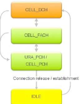
Figure 7: The UMTS state machine URA_PCH or Cell PCH activated
Figure 7 shows how state transitions are different when URA_PCH/CELL_PCH are used in the network and supported by the device.
In the URA_PCH state, the UE is known at the UTRAN Registration Area (URA) level in the Serving Radio Network Controller (SRNC) but it is not allocated with any dedicated radio resources and it is not able to transmit or receive any control signals or data packets. Essentially, the smartphone is in “sleep” mode, but since the RRC connection is maintained based on the most recent URA location, it enables the cellular network to still stay in a logical connection to the device, subsequently not breaking the application’s connection with their respective servers.
Similarly, in the Cell_PCH state, the smartphone is in “sleep” mode, but the RRC connection is maintained based on most recent cell location to enable the device to be directly addressed at its current cell when the network needs to wake up the device due to new data arriving. The device will update its location to the radio network whenever it moves from one cell area to another. Maintaining the UE context in the cellular network and not releasing the logical connection permits much faster network access than in idle mode, while still keeping power consumption as low as in Idle.
In Cell_DCH state a feature package called Continuous Packet Connectivity (CPC) improves the UE power consumption in that state (battery life time) and air interface capacity. The savings can be exploited either by enhancing the "always-on" experience by keeping inactive devices longer in the Cell_DCH state, or by further improving the device’s battery life time. UE DTX (discontinuous transmission from the UE) allows UEs to switch off continuous transmission of the dedicated physical control channel (DPCCH) when there is no information to transmit in the uplink. When this is the case, only a minimum of transmission is needed to maintain synchronization and control power. Two immediate benefits of switching off transmission are reduced battery consumption and reduced interference, which increases uplink capacity (in terms of number of users).
1.4.2 THE LTE STATE MACHINE
In LTE, 3GPP supports only two states for a UE2, namely, RRC IDLE, RRC CONNECTED. In the RRC CONNECTED state, there is a RRC context established – that is, the parameters necessary for communication between the terminal and the RAN are known to both entities. The cell to which the terminal belongs is known and the identity of the terminal is known, and these are used for signaling purposes between the terminal and the network. RRC CONNECTED is meant for data transfer to and from the UE. But discontinuous reception (DRX) can be configured to reduce power consumption, and long DRX operation is intended to achieve similar benefits as the PCH states in the UMTS system. Although expressed differently in the specifications, RRC CONNECTED can be thought of as having two sub states, IN SYNC and OUT OF SYNC, depending whether the uplink is synchronized to the network or not.
Figure 8: LTE State Machine has only two main states
2
1.4.3 INTERACTION BETWEEN UMTS AND LTE
Figure 9: Interaction between UMTS and LTE state machines (derived from 3GPP 36.331)
Figure 9 addresses network and device transitions from UMTS to LTE networks. Devices in a connected state undergo in-session handover to the corresponding connected state in the other technology. In all other cases, reselection occurs between the non-connected states of the two technologies.
1.5 QOS FOR APPLICATIONS, POLICY & CHARGING
The explosion in data traffic in recent years can be attributed to the continuous growth and proliferation of a broad range of multimedia applications. While most users are not concerned with the details of how a particular service is implemented, users are interested in comparing the same service offered by different providers in terms of universal agreed upon parameters that focus on user-perceivable effects, rather than their causes within the network, and are independent of the specific network architecture or technology. Important parameters from a user perspective include end-to-end delay (including delays in the terminal, network and servers), delay variation due to the inherent variability in arrival times of individual packets in packet networks and throughput. Introduction of newer services such as VoIP, gaming, etc., will require strict guarantees on delay and packet loss in order for these services to be viable, thus highlighting the need for E2E (end-to-end) QoS (Quality of Service) mechanisms in the network.
QoS is a measure of the ability of the network to provide the necessary levels of service to the various applications and network flows. The spatial and temporal dynamics of radio environments coupled with the different error characteristics present unique challenges in meeting the necessary QoS demands needed to support the diverse end user applications.
There is a need to standardize simple and effective QoS mechanisms for multi-vendor mobile broadband deployments. Such QoS mechanisms could allow the access operator to enable service and subscriber differentiation and to control the performance experienced by the packet traffic of a certain service and subscriber group. To support QoS guarantees for various multimedia services, 3GPP clearly defines the end-to-end QoS architecture for UMTS and introduces several bearer and processing mechanisms to ensure UMTS can make full use of its technical advantages to offer differentiated services for users. 1.5.1 UMTS QOS
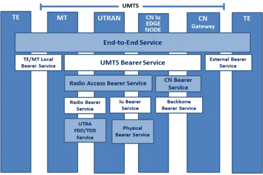
3GPP TS 23.107 specifies the UMTS QoS concept and architecture to best meet the requirements of end-to-end service flows in mobility networks. The UMTS QoS Architecture defines a layered QoS framework where there are multiple layers spanning different sections of the network between different nodes and is shown in Figure 10. An E2E service spans from one Terminal Equipment (TE) to another TE and is the top most layer of this architecture. The E2E service may have a certain QoS, which is provided for the user of a network service who decides whether they are satisfied with the provided QoS. A bearer service with clearly specified characteristics is set up from source to destination to meet the network QoS requirement. Bearer services provide QoS based on services provided by the layers below them that include TE/MT local bearer service, a UMTS bearer service and external bearer service. The bearer is the basic enabler for traffic separation because it provides differential treatment for traffic with differing QoS requirements. The concept of the bearer and the associated signaling procedures further enables the system to reserve system resources before packet flows that are mapped to that bearer are mapped into the system. The UMTS bearer service is comprised of the Radio Access Bearer service and the Core Network Bearer service, which, in turn, have sub-layers. The UMTS operator offers services provided by the UMTS bearer service that provides the UMTS QoS. Every bearer service must fulfill a set of QoS requirements.
UMTS QoS classes are defined by taking into account the different error characteristics of the air interface and accordingly, the QoS mechanisms defined must be robust. UMTS (3GPP 23.107) defines four different QoS classes namely:
Conversational class Streaming class Interactive class Background class
These different QoS classes are distinguished from each other based on the delay sensitivity of the traffic supported by each.
Conversational and Streaming classes are used to serve real-time traffic flows, which are very sensitive to the delay. Examples of Conversational classes include real-time services like video telephony. Interactive class and the Background class are mainly meant for applications like WWW, email, FTP, News and Telnet. Since these classes are less delay sensitive compared to the conversational and streaming classes, both the classes provide better error rate by means of channel coding techniques and retransmissions. Packet retransmission is initiated whenever packet error, packet loss or packet order mismatch takes place because these classes expect high throughput and less error rates even though they are delay insensitive. The main difference between Interactive and Background class is that Interactive class is mainly used for interactive applications like interactive email and interactive Web browsing, while Background class is meant for background downloads or emails and background file downloading (3GPP 23.107). Since the scheduling algorithm gives more priority to the interactive class than the background class, the background applications use the transmission resources only when the interactive applications do not need them. Accordingly, performance targets for audio and video applications form the basis of network QoS classes. UMTS bearer service (QoS) attributes describe the service provided by the UMTS network to the user of the UMTS bearer. Key QoS service attributes (3GPP 23.107) include:
Maximum bit rate (kbps) Guaranteed bit rate (kbps) Delivery order (y/n) etc.
The parameters related to throughput/bitrates are separated for uplink/downlink in order to support asymmetric bearers.
1.5.2 LTE QOS
3GPP LTE and SAE have enhanced the QoS mechanisms in UMTS. The evolved network, called Evolved Packet System (EPS), introduces the concept of default bearer that is setup when the user attaches to the network to effectively enhance user experience, reduce service setup latency and realize "always online" IP connections. The QoS parameters of the default bearer include the subscription data obtained from the Home Subscriber Server (HSS) whose values can be modified through PCRF interactions or local configurations. Other EPS bearers in connection with the same PDN are called dedicated bearers whose setup or modification can be triggered by the network side only. The main
by the access network operator. Therefore, it is natural that the access network and service owner assigns the QoS level per packet flow associated with a particular service. In addition, the bearer level QoS parameter values are always allocated by the packet core network. LTE supports end-to-end QoS where bearer characteristic are defined and controlled throughout the duration of a session between the mobile device (UE) and the P-GW. LTE QoS is characterized by:
QCI (QoS Class Identifier)
ARP (Allocation and Retention Priority) Maximum Bit Rate (MBR)
Guaranteed Bit Rate (GBR)
Aggregate Maximum Bit Rate (AMBR)
Bearer types are classified into two main classes: Guaranteed Bearers and Non-Guaranteed bearers, with guaranteed and non-guaranteed rates with QCI labels providing specific values of packet delay and loss that can be tolerated for any given bearer. The QCI value helps setup access point parameters used to control bearer level packet transfer (e.g. scheduling weights, admission thresholds, queue management thresholds, and link layer protocol configuration). ARP is used to decide the priority of admission or dropping off of dedicated bearers in case of limited network resources. Both GBR and non-GBR bearers are defined by QCI and ARP.
Besides QCI and APR, every GBR bearer is also associated with the parameters GBR and MBR. GBR bearers are used to carry voice, video and real-time gaming services through dedicated bearers. The GBR represents the bit rate that can be expected to be provided by a GBR bearer, while the MBR indicates the upper limit of GBR bearer.
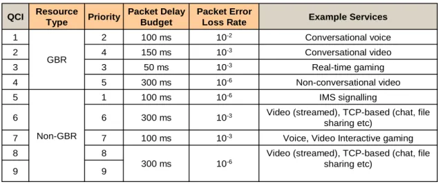
Non-GBR bearers are used to carry best effort services and/or services whose bit rates cannot be guaranteed. To improve bandwidth utilization, EPS defines the AMBR. AMBR is an IP Connectivity Access Network (IP-CAN) session level QoS parameter of every PDN connection. Multiple EPS bearers for the same PDN connection share the same AMBR value. Each non-GBR bearer can potentially make use of the whole AMBR if other EPS bearers do not transfer any services. Theoretically, an AMBR restricts the total bit rate of all the bearers sharing this AMBR. AMBR can be classified into UE-AMBR and Access Point Name (APN)-AMBR. Table 1 lists standardized QCI characteristics defined in EPS.
Table 1: Standardized QCI characteristics: 3GPP TS 23.401 V8.1.0 (2008-03)
To ensure interoperability between UMTS Terrestrial Radio Access Network (UTRAN) and Evolved UTRAN (E-UTRAN), an appropriate mapping between the EPS QoS Class Identifier (QCI) parameter and Universal Mobile Telecommunication System (UMTS) QoS parameter is designed.
1.5.3 QOS MANAGEMENT AND POLICY FRAMEWORK
The QoS management functions provide the functionality needed to establish, modify and maintain a UMTS Bearer Service with a specific QoS. The QoS management functions of all UMTS entities together shall ensure the provision of the negotiated service between the access points of the UMTS bearer service.
Policies are a set of rules that an operator can define and enforce in a telecom network, both within an operator domain and across different operator domains. The 3GPP standards have defined a Policy Charging and Control architecture that merges the service-based local policy and flow-based charging functionality into the model called PCC. Such a model allows for more efficient real-time control of the service flows in gateways.
In the PCC model, there are three key functional elements: a central policy repository, the policy decision point (PDP) and the policy enforcement point (PEP). Decisions made in the policy decision point (PCRF in 3GPP Rel-7), based on rules for network operations, are communicated to the policy enforcement points where these decisions are translated to QoS rules of individual service data flows to be enforced on the traffic plan.
The PCRF policy entity binds the service and transport layers. The PCRF collates subscriber and application data, authorizes QoS resources, and instructs the transport plane on how to proceed with the underlying data traffic. The PCRF is connected on its northbound Rx interface to the Application Function (AF). The AF resides on the service plane and represents applications that require dynamic policy and QoS control over the traffic plane behavior. The PCRF is connected on the traffic plane via the Gx interface to the Policy and Charging Enforcement Function (PCEF) that typically resides in a gateway node. The PCEF's role includes traffic detection and resultant policy enforcement. A Subscriber Policy Register (SPR) node also provides subscriber specific data to the PCRF, to assist in evaluating policy decisions.
Voice, Video Interactive gaming 10-3 100 ms 7 7 9 9
Video (streamed), TCP-based (chat, file sharing etc)
10-6 300 ms
8 8
Video (streamed), TCP-based (chat, file sharing etc) 10-3 300 ms 6 6 IMS signalling 10-6 100 ms 1 Non-GBR 5 Non-conversational video 10-6 300 ms 5 4 Real-time gaming 10-3 50 ms 3 3 Conversational video 10-3 150 ms 4 2 Conversational voice 10-2 100 ms 2 GBR 1 Example Services Packet Error Loss Rate Packet Delay Budget Priority Resource Type QCI
The service data flows can be thought of as a set of packet flows, typically IP flows and QoS control is applied per service data flow in the PCEF. The PCEF utilizes PCC (policy and charging control) rules to classify traffic by service data flow. Rules can be pre-defined or dynamically provisioned in the PCEF. Dynamic PCC rules are derived within the PCRF from information supplied by the AF (such as requested bandwidth), PCEF data (such as requested QoS at traffic level by user) and other Subscriber specific data if available. Provisioning of rules via the Gx interface to the PCEF can take place in two ways:
1. "Pushed" – i.e. unsolicited provisioning, where the PCRF may decide to provision PCC rules without obtaining a request from the PCEF; or
2. "Pulled" – i.e. where Provisioning has been solicited by a request from the PCEF
Each rule uses a series of data flow filters to allow the PCEF to detect the relevant traffic plane packets. The resultant activated PCC rule contains a QoS class identifier and the uplink plus downlink bit-rates authorized for the service data flow. As each PCC rule can only be bound to a single data bearer, this may require a series of rules to be installed to control QoS across multiple underlying traffic bearers. The actual policy enforcement procedures for authorized QoS per PCC Rule is bearer dependent Possible procedures include Packet scheduling, data packet (Diffserv) marking, and packet discarding. Event mechanisms can be set by the PCRF in the PCC rules to cause the PCEF to inform it of changes in the underlying traffic bearer.
1.6 DEVICE PLATFORMS
Device platforms have tremendous impact on not only how an application interacts with the device but also on how it communicates with the network. They are the foundational building blocks of a smartphone as they manage software resources and hardware interaction. Most smartphones in the market today have one of these popular Operating Systems (OS): Apple’s iOS, Google’s Android, Microsoft’s Windows Phone, RIM’s BlackBerry OS, HP’s WebOS, Nokia’s Symbian, and embedded Linux distributions such as Maemo and Meego. RIM’s Blackberry OS is a leading operating system amongst enterprise and business customers. Also, among these operating systems iOS and Android have gained popularity in the past three years with a collective market share of about 60 percent in 20113. Analysts have also predicted that Windows Phone will become the third most preferred OS by the year 2015 with a market share of approximately 20 percent4. In this section we will focus on these four OSs and how they help smartphones efficiently interact with the network. The following table provides a snapshot of topics that are common to the four OSs, which will be covered in the subsections below.
3
http://www.gartner.com/it/page.jsp?id=1622614 4
Table 2: Comparison of 4 major device OS
OS
Features Apple iOS Google Android
Microsoft
Windows Phone Blackberry
Detection of network type Yes via “Reachability” Yes via ConnectivityManager Yes via NetworkInterface Type
Yes via Network Manager Asynchronous
request/response
Supported by
default Supported by default
Supported by default
Supported by default Data caching Yes by
default
Not supported by default
Not supported by
default Yes by default Data Compression Yes by
default
Not enabled by default
Not supported by
default. Yes by default Supports network
efficient data formats (JSON and
XML)
Yes (iOS 5.0) Yes Yes Yes
Push notification Yes (4.0 and
higher) Yes (2.2 and higher) Yes Yes
1.6.1 IOS
iOS was developed by Apple Inc. and was first introduced in 2007 when the first iPhone launched. Apps for the iOS can be developed using the Cocoa Touch framework, which is implemented using objective-C. Web applications that run on the Safari browser are built using Web2.0 technology. iOS offers many features that help its devices and their applications to efficiently utilize network resources and provide a good end-user experience. An application has to be aware of the current network status to determine if data packets can be routed through the cellular data network. If no network connection is available, or if the signal strength is too low to sustain the data transfer, the application can switch to offline mode to preserve battery life in the connected state. iOS provides a sample application called “reachability,” which can be used to determine the network status5. The advanced Safari browser included in iOS supports the latest HTML5 offline data storage features. The offline storage means a web app can store session data locally in a cache on the device, using either a simple key/value data API, or a more advanced SQL interface. The data is persistent among Safari launches, meaning apps start up faster, are less dependent upon the network, and perform better6. iOS supports data compression formats such as gzip and deflate and automatically adds “Accept-Encoding” header in the requests and decompresses the response. This helps in saving the amount of data that needs to be transferred over the network for network enabled applications. Apple also introduced support for push notification in iOS 4.0. Thus an application is not required to keep polling the server for updates or run in the background. If an update for an event occurs,
5
https://developer.apple.com/library/ios/#samplecode/Reachability/Introduction/Intro.html#//apple_ref/doc/uid/DTS40007324-Intro-the server would send a push notification to https://developer.apple.com/library/ios/#samplecode/Reachability/Introduction/Intro.html#//apple_ref/doc/uid/DTS40007324-Intro-the application. Starting with iOS 5.0 Apple supports native parsing for lightweight data formats such as JSON without having to use third party libraries. The OS handles HTTP threads asynchronously so that a network error in sending a request or receiving a response does not block the main thread preventing the application from becoming non-responsive. There are third party libraries like Three20 and ASIHTTPRequest that support handling of multiple simultaneous requests and responses independent of each other7. The advantages of asynchronous request and response are detailed in section 3.3. Apple also joined efforts with Nokia to introduce “Network Controlled Fast Dormancy” in iOS 4.2. This technology helps cut down signaling traffic and increase battery life for the device. Network controlled fast dormancy and its advantages are detailed in subsequent sections.
1.6.2 ANDROID
Android is a Linux-based open source OS developed by Open Handset Alliance (OHA) led by Google. Applications for Android are written in Java8. The OS supports asynchronous handling of multiple HTTP threads and completion of tasks in the background mode. The main UI activity is kept separate from other threads so that main UI is not blocked due to pending operation on other threads. Android provides ConnectivityManager to determine the availability and type of network connection. Thus an application can check the connectivity status before starting the update of a scheduled background service or data cache. The OS also provides techniques to delay the download of bandwidth intensive applications or data until the device is connected to Wi-Fi9. This Wi-Fi offloading facility takes the burden away from the cellular data network. HTTP caching is supported in Android and its persistent cache size is 6MB. The WebKit browser in Android supports a cache memory of 8MB10. Like iOS, Android also supports data formats such as JSON and XML for text encoding. These formats are supported by most web servers and are easier and faster to parse and present results to the end user. Starting version 2.2, Android supported Cloud to Device Messaging (C2DM), which enables servers to send push notification to the device whenever fresher data becomes available. This increases network efficiency as an application does not have to wake up periodically and poll the server for data, where, sometimes, new data might not be available. This also helps preserve battery life of the device. Android supports data compression formats such as gzip and deflate but compression is not enabled by default.11 In conclusion, Android, due to its openness nature, has left it to the developers to come up with solutions to make their apps network efficient and does not offer concrete guidelines on how to build network friendly applications.
1.6.3 WINDOWS PHONE
Windows phone, created by Microsoft, is the evolution of the Windows Mobile platform that began with Windows CE in 1996. Microsoft released the SDK to developers in September 2010. Development for Windows Phone application is done using the following Visual Studio 2010 (or higher), expression blend for design purposes, C#, .Net, Sliverlight for business applications, and XNA for game development. As with iOS and Android, this OS also supports asynchronous handling of network requests and response out of the box. There are two classes supported in .Net framework that handle asynchronous
7
GSMA - Smartphone Challenge: Guidelines for development of network friendly applications
8 Using Internet data in Android applications; http://www.ibm.com/developerworks/xml/library/x-dataAndroid/?ca=drs-9http://developer.android.com/training/monitoring-device-state/manifest-receivers.html
10
Rajiv Vijayakumar, Understanding mobile web browser performance, Qualcomm Incorporated.
http://assets.en.oreilly.com/1/event/60/Understanding%20Mobile%20Web%20Browser%20Performance%20Presentation.pdf 11
request/response for accessing data from the Internet: WebRequest class and HttpWebRequest class12. The NetworkInterfaceType property in the NetworkInterface class provides the network type servicing Internet requests. However this information is not available instantaneously and therefore Microsoft recommends checking network connection type on a background thread. The OS does not support caching by default. Caching of network data is only partially supported by the Silverlight engine13. An example of how an offline data cache can be implemented is available14. Memory, storage and communication bandwidth conserving data formats such as JSON and XML are supported by the OS. However serialization using the above data formats comes at the cost of increased processing resources. As with Android this OS does not support compression by default. The industry uses multiple software libraries to perform decompression for content that is gzip-compressed by a web server. The platform provides a push client service to enable push notifications by default. A comprehensive explanation of the service is explained here15. It is rumored that Windows Phone 8, code named “Apollo” will have features such as data smart, which will help users save cellular data when possible and avoid “bill shock,” and Wi-Fi offloading, which detects Wi-Wi-Fi networks and connects to them automatically without requiring any user interaction.
1.6.4 BLACKBERRY OS
BlackBerry 10 is a multitasking, microkernel operating system built upon the QNX Neutrino RTOS, which has a long history in the automotive, industrial, medical and networking markets. BlackBerry 10 runs device drivers, file systems, networking stacks and applications outside of the OS kernel as memory-protected components.
This modular architecture enables the design of self-healing systems that can recover gracefully from software faults in applications or system-level services; it also allows systems to support new or upgraded services on the fly. The BlackBerry 10 networking stack executes outside the kernel, like the other system-level processes, and presents developers with a single unified interface, regardless of the configuration and number of networks involved. Its active networking executable implements a zero-copy architecture, which provides the best possible performance for network interaction. Based on the open NetBSD, the networking stack supports all the more common protocols and networking functionality: UDP, TCP, IP (v4 and v6), broadcast, multicast, forwarding, routing, sockets, multilink PPP, PPPoE, DHCP, DNS, NFS, NTP, IPsec, and so on.
The web browser for BlackBerry 10 is based on WebKit, an open source project and the most popular web browser layout engine, used in Apple Safari, Google Chrome, Amazon Kindle eBook reader, and many other browsers. The browser for BlackBerry 10 enables true desktop-style browsing on smartphones and tablets, with Adobe Flash support and industry-leading HTML5 compatibility. Its hardware-accelerated features include CSS3 animations and transitions, 2D and 3D canvas, as well as embedded 1080 pixel HTML5 and Flash video, and smooth 60 fps touch scrolling. The browser incorporates a regular, up-to-date WebKit base for the latest features and defect fixes.
12http://msdn.microsoft.com/en-us/library/ 13
2 PROBLEM DEFINITION
2.1 IMPACT OF APPLICATION BEHAVIOR
The reality of user behavior in consuming more content than what is produced, the popularity of multimedia services and the lack of processing power on UEs results in far greater traffic flowing downstream into UEs than flowing upstream from UEs into the cloud. Naturally, communication channels are typically asymmetric reserving greater bandwidth for the downlink vs. the uplink. In spite of the asymmetric bandwidth allocation, mobile networks are seeing significant traffic pressure on the downlink due to the sheer number of applications using the networks and the multimedia heavy nature of the traffic generated by many of the applications.
Figure 11: Weekly application traffic for different subscriber clusters of a new Android smartphone model (high-end with large screen) at one specific operator
(Source: Ericsson Traffic and Market Data Report Nov 201116)
As shown in Figure 11, the dominant contributors to mobile traffic are online media and web browsing, which tend to be extremely asymmetric with data primarily flowing downstream from the cloud into the UEs. Another emerging class of traffic on the downlink is OS and application updates, which are delivered over-the-air to the UEs17.
16 Ericsson Traffic and Market Data report – Nov 2011
(http://www.ericsson.com/res/investors/docs/2011/cmd/traffic_and_market_data_report_111107.pdf ) 17
Ericsson White Paper July 2010 - Delivering capacity for mobile broadband - an eminently manageable challenge (http://www.ericsson.com/news/100709_wp_hspa_244218600_c
Average weekly application traffic for different subscriber clusters of a new Android smartphone model
1 10 100 1000 10000
online video online audio web browsing social networking
app store email
[M B / w e e k / s u b s c rib e r] 50-55% 55-60% 60-65% 65-70% 70-75% 75-80% 80-85% 85-90% 90-95% 95-100%
Figure 12: Traffic Mix for data plans
(Source: Ericsson Traffic and Market Data Report Nov 2011)
In addition, a number of symmetric applications such as file sharing or Peer-to-Peer (P2P), mobile Voice over IP (VoIP) and gaming contribute to traffic on the downlink. However, P2P traffic has been on the decline over the last several years as first audio content and then video content became readily available through legitimate storefronts. In addition, relative to other traffic types, Mobile VoIP and Mobile Gaming are low bit rate services, which do not impact the overall traffic as much in spite of a very large number of concurrent sessions in use.
As UEs become more capable, services such as video conferencing, User Generated Content (UGC) uploads, P2P applications, video surveillance and augmented reality are gaining popularity. Further, as voice services transition to VoIP in LTE networks, the potential increased traffic from voice will also contribute to the uplink traffic mix. The aggregate of these services is making network capacity requirements more symmetric and resulting in significant pressure on the uplink capacity. Foreseeing this trend, HSPA and LTE have increased the relative throughput of the uplink vs. the downlink compared to earlier technologies18 and further LTE also allows for more flexible spectrum allocation to account for evolving network traffic usage patterns.
Nevertheless, until LTE is widely deployed, accelerated growth in uplink traffic will require immediate and unique solutions on deployed HSPA and HSPA+ networks.
Figure 13: Global Sales of Devices by Type (in Millions)
(Source: Strategy Analytics& ABI Research)
As shown in Figure 13, Machine-to-Machine (M2M) devices are expected to grow into a significant share of the devices on the network. These M2M applications have diverse network requirements varying from heavy signaling-low throughput in the case of geo-tracking to low signaling-high downlink throughput in the case of Near-Video On Demand (VOD) to low signaling-high uplink throughput in the case of webcams. Further, M2M applications may also be widely distributed in large numbers due to the low cost-low maintenance nature of the UEs resulting in rapid growth in M2M traffic. In addition, the wide distribution of these devices will require remote manageability using OTA software updates further adding to the traffic demands on the network.
2.2 IMPACT OF DEVICE PLATFORM BEHAVIOR
As the 3G service gets widely deployed and next-generation service starts to kick off, various types of mobile devices are introduced into the market. Today’s mobile devices are multi-functional devices capable of hosting a broad range of applications for both business and consumer use. Providing this ever-increasing capability is the mobile operating system, which is also evolving at a rapid pace, including the provision of frequent updates or upgrades to the end users for downloading to their mobile device. As discussed further in this section, this can cause an impact both to the mobile device itself, such as reduced battery life, and network performance degradation, such as signaling storm.
2.2.1 CONTROL PLANE IMPACT
As the rapid growth of various mobile devices being supported by UMTS/LTE network continues, network congestion becomes one of the biggest issues, highlighted by the popularity of smartphones and M2M usage. However, the capacity crunch is not only due to increasing user data traffic, but also in increasing signaling traffic. Due to the fact that the applications that run on smartphones and M2M have different behavioral characteristics compared to that of traditional voice and simple data, which run on the wireless network, they pose a large signaling traffic challenge to the networks which support. For example, smart phones and M2M have an increasing number of applications that send only a small amount of data, but the transmission frequency of the packets is relatively high. Users of smartphones make constant queries to the network as they move among cell sites to push email, access social networking tools and conduct
other repetitive actions. These always-on applications also rely on keep-alive messages. As a result, while data traffic is growing, by many accounts, signaling traffic is outpacing actual mobile data traffic by 30 to 50 percent, if not higher. As another example, a web-based IM user may send a message but then wait a couple of seconds between messages. To preserve battery life, the smartphone moves into idle mode. When the user pushes another message seconds later, the device has to set up a signaling path again. The base station controller (i.e., RNC) spends a lot of its resources trying to process such signaling, which prevents it from doing other things like allocating additional resources for data.
There are several common smartphone behaviors which could potentially bring signaling storm to the network and need to be considered and handled within the ecosystem. Some key behaviors are:
Fast dormancy
Heartbeat for always-on application Constant push service
Network (re-)attachment
2.2.1.1 FAST DORMANCY NETWORK IMPACT
It is essential to keep the UE power consumption low while having to do frequent transmissions. The original idea in 3GPP was to provide the Radio Resource Control (RRC) states Cell_PCH and URA_PCH to allow for very low UE power consumption. Here, when a data transmission is over, the UE is moved to PCH state quickly and there would be no need to move UE to idle state for low power consumption. The motivation to avoid idle state is because the next packet would then cause packet connection (PS RAB) setup leading to increased latencies and increased signaling traffic in the network.
Figure 14: Device-triggered Fast dormancy increases state changes and signaling when PCH state not is used
Nevertheless, it is common practice that many networks are configured with relatively long inactivity timers for Cell_DCH and for Cell_FACH states, resulting in infrequent transitions to the PCH state. As a result, transmissions of even a small packet may lead to high battery drain. In order to keep UE power consumption low, UEs have implemented proprietary (that is, a functionality not defined by 3GPP standards) Fast Dormancy. When using such a Fast Dormancy, the mobile application informs the radio layers when the data transmission is over, and the UE can then send Signaling Connection Release Indication (SCRI) to the RNC simulating a failure in the signaling connection. Consequently, the UE releases RRC connection and moves to idle state. That approach keeps the UE power consumption low, but it causes frequent setup of packet connections unnecessarily increasing network signaling load. There are also differences between different UE vendors on how they implement Fast Dormancy functionality. In addition to the high signaling load, the network counters indicate a large number of signaling connection failures as this battery saving method cannot be distinguished from a genuine signaling connection failure in the network.
2.2.1.2 HEARTBEAT FOR ALWAYS-ON APPLICATION
One of the key driving forces of the smartphone is the huge number of online applications available to its users and its ability to provide a mobility platform for user to access those applications and information anytime and anywhere. For real-time Internet applications, the logical always-on connection between the server and client is required, resulting in frequent or periodic small heartbeat packets to be sent as a keep-alive message to maintain the connection. Since there is no coordination between the application and network on when these small heartbeat packets will be sent, and considering that mobile devices are frequently switched to idle mode to save battery, many times these heartbeat packets end up being sent during the mobile device’s idle state, which, in turn, triggers the device to continually switch between active and idle model over short period time and create massive signaling traffic. Although heartbeat is mainly associated with a given application and can be considered as having impact to the application itself, the smartphone platform becomes tightly coupled with many always-on applications which further contribute to the heartbeat signaling traffic. The following figure demonstrates signaling traffic created by different platforms. In addition, the smartphone platform also has its own heartbeat mechanisms to keep the device connected to the server all the time.
Figure 15: Signaling traffic generated by Apps
2.2.1.3 CONSTANT PUSH SERVICE
Currently the major smartphone platforms support push notification mechanisms to allow third party applications to use device platform vendors’ push server and push mechanism to convey some short notification information to the client in the device. This is done in order to let the user receive the latest update or information from the application server. Some applications running on particular device platform can create more push related signaling traffic. Since these push servers reside outside the operator’s network and are not coordinated with the device’s actual network connection status, such as idle or active mode, many push messages may therefore be sent while the device is on idle mode, which will trigger unnecessary signaling traffic, such as paging messages, network connection and release messages.
Figure 16: Push Service towards devices
2.2.1.4 NETWORK ATTACHMENT
Since the notion of “always online” is critical to the end user of smartphones and the smartphone is becoming the device of choice using operators’ next-generation mobile broadband networks, many mobile devices are designed to aggressively keep connecting to the broadband network as early as possible to ensure a good user experience. However, due to different device platform implementation, different level of signal traffic impact can be expected. For example,