arXiv:physics/0007033v2 [physics.optics] 20 Jul 2000
The Channel Capacity of a Fiber Optics
Communication System: perturbation theory
Evgenii Narimanov and Partha Mitra
Abstract— We consider the communication channel givenby a fiber optical transmission line. We develop a method to perturbatively calculate the information capacity of a non-linear channel, given the corresponding evolution equation. Using this technique, we compute the decrease of the chan-nel capacity to the leading order in the perturbative param-eter for fiber optics communication systems.
I. Introduction
T
H e performance of any communication system is ul-timately limited by the signal to noise ratio of the re-ceived signal and available bandwidth. This limitation can be stated more formally by using the concept of channel capacity introduced withing the framework of information theory[1]. The channel capacity is defined as the maximum possible bit rate for error-free transmission in the presence of noise. For a linear communication channel with additive white Gaussian noise, and a total signal power constraint at the input, the capacity is given by the celebrated Shannon formula[1] C = Wlog 1 + P0 PN (1) whereW is the channel bandwidth,P0is the average signal power, andPN is the average noise power.Current optical fiber systems operate substantially below the fundamental limitation, imposed by the Eq. (1). How-ever, a considerable improvement in the coding schemes for lightwave communications, expected in the near future, may result in the development of systems, whose efficiency may approach this fundamental limit.
However, the representation of the channel capacity in the standard form (1) is unsuitable for applications to the actual fiber optics systems. It was obtained based on the assumption of linearity of the communication chan-nel, while the modern fiber optics systems operate in a substantially nonlinear regime. Since the optical transmis-sion lines must satisfy very strict requirements for bit-error-rate (10−12to 10−15), the pulse amplitude should be large
enough so that is can be effectively detectable. The in-crease of the number of wavelength-division multiplexing (WDM) channels[2] in the modern fiber optics communi-cation systems also leads to a substantial increase of the electric field intensity in the fiber. As a consequence, the Kerr nonlinearity of the fiber refractive indexn=n0+γI
(where I is the pulse intensity) becomes substantial and should be taken into account.
In the present paper we consider corrections to the chan-nel capacity of the optical fiber communication system, originating from the nonlinearity of the fiber. The tech-nique that we use involves a perturbative computation of
the relevant mutual information and subsequent optimiza-tion. To our knowledge, this method appears to be sub-stantially new.
II. Fiber Optics Communication System as an Information Channel
We consider a typical fiber optics communication sys-tem, which consists of a sequence ofN fibers each followed by an amplifier (see Fig. 1). The amplifiers have to be in-troduced in order to compensate for the power loss in the fiber. An inevitable consequence of such design, however, is the generation of the noise in the system, coming from the spontaneous emission in the optical amplifiers. For sim-plicity, we will assume that all the fibers and the amplifiers of the link are identical.
The information is encoded in the electric field at the “imput” of the system, typically using the light pulses sent at different frequencies. The available bandwidth of the amplifiers as well as the increase of the fiber absorption away from the “transparency window” near the wavelength
λ= 1.55µm, limits the bandwidth of the fiber optic com-munication system.
The maximum amount of the information, that can be transmitted through the communication system per unit time, is called the channel capacity C. According to the Shannon’s basic result[1], this quantity is given by the max-imum value of the mutual information per second over all possible input distributions:
C = maxpx{H[y]− hH[y|x]ipx} (2)
The mutual information
R = H[y(ω)]− hH[y(ω)|x(ω)]ipx (3)
is a functional of the “input distribution”px[x(ω)], which
represents the encoding of the information using the elec-tric field components at different frequences
Ein(t) = Z
W
dω x(ω) exp (iωt) (4)
The entropyH[y(ω)] is the measure of the information re-ceived at the output of the communication channel. How-ever, if the channel is noisy, for any output signal there is some uncertainty of what was originally sent. The con-ditional entropy H[y(ω)|x(ω)] at the output for a given x(ω) represents this uncertainty.
The entropiesH[y(ω)] andH[y(ω)|x(ω)] are defined in terms of the corresponding distributions p(y) and p(y|x) via the standard relation
H ≡ −
Z
Fig. 1. The schematical representation of a fiber optics communica-tion channel
wherep≡py(y) for the entropyH[y(ω)], andp≡p(y|x)
for the entropyH[y(ω)|x(ω)], and the functional integral is defined in the standard way
Z Dξ(ω)≡ lim M→∞cM ΠMm=1 Z dξ(ωm) (6) where is a normalization constant.
For any communication link, the signal power is limited by the system hardware. Therefore, the maximum of the mutual information in (1) should be found under the con-straint of the fixed total powerP0 at the input:
P0 = Z
Dx(ω)|x(ω)|2px[x(ω)] (7)
If the propagation in the communication channel is de-scribed by a linear equation, then the input-output relation for the system is given by
y(ω) =K(ω)x(ω) +n(ω) (8)
wheren(ω) is the noise in the channel. In this approxima-tion, the problem of finding the maximum of the mutual information can be solved exactly, with the corresponding input distribution px being Gaussian[1]. If the amplifiers
compensate exactly for the power losses in the fibers, the Channel Capacity is given by the Shannon formula (1).
As follows from (1), the better bit rates can be obtained for the higher signal-to-noise ratio P0/PN. With this in
mind, the optics fiber communication systems are designed to operate with the pulses of high power. As a result, the optics fiber links operate in the regime, in which due to the Kerr nonlinearity the refraction index of the fiber strongly depends on the local electric field intensity. Therefore, a modern fiber optics communication system is, in fact, an essentially nonlinear communication channel, and cannot be adequately described within the framework of the Shan-non’slineartheory.
III. The Model
The first step in the calculation of the channel capacity is to find the “input-output” relation for the communication channel. The time evolution of the electric field in the fiberE(z, t), wherezis the distance along the fiber, can be accuarately described in the “envelope approximation”[2], when
E(z, t) = A(z, t) exp (i(β0z−ω0t)) + c.c. (9)
where the function A represents the slowly (compared to the light frequency) varying amplitude of the electric field
in the fiber. The evolution of A(z, t) is described by the equation ∂A ∂z +β1 ∂A ∂t + i 2β2 ∂2A ∂t2 + α 2A=iγ|A| 2 A (10)
Here the coefficientsβ describe the frequency dependence of the wavenumber β(ω) = β0+β1ω+β2 2 ω 2+O ω3 (11) whereω is measured from the center of the bandω0.
The equation (10) neglects the effects such as the stimu-lated Raman scattering and the stimustimu-lated Brillouin scat-tering[2], compared to the Kerr nonlinearity of the refrac-tion index of the fiber, represented by the termγ|A|2A.
The optical amplifiers incorporated into the communi-cation system (see Fig. 1) compensate for the power losses in the fiber, but due to spontaneous emission each of them will inevitably introduce noise n(t) = exp (iω0t)R
dω nωexp (iωt) into the channel. Generally,
even in a single optical amplifier, the noise distribution at any given frequencyω0+ω within the channel bandwidth
n(ω) is close to a Gaussian: pn[n(ω)] ∼ exp " −|n(ω)| 2 Pω N # (12) This is even more so in a system with many independent amplifiers, due to the Central Limit Theorem. For simplic-ity, the noise spectrumPω
N can be assumed to be flat.
If the envelope function just before the amplifier is
A(t)≡A0
ωexp (iωt), then immediately after the amplifier
Aω = exp
α 2d
A0ω+nω (13)
wheredis the span of a single fiber.
The equations (10), (13) define the evolution of the elec-tric field envelope over one “fiber-aplifier” link of the com-munication system. The total “input-output” relation will then involve solving the corresponding equations for allN
iterations of the single fiber-amplifier unit.
IV. The Perturbative Framework
If one is able to calculate the “output” signal y(ω) in terms of the “input” x(ω) and the noise contributions of each of the amplifiersn{ωα}, α= 1, . . . , N,
y(ω) = Φx(ω);nω{1}, . . . , nω{N}
(14) then the the conditional distributionp(y|x) can be simply calculated as follows: p(y|x) = ΠNα=1−1 Z Dnω{α} pn h nω{α} i × pn h y(ω)−Φx(ω);nω{1}, . . . , nω{N} i (15) wherepnis the distribution function of the noise, produced
then be directly related to the input distributionpx(x) via
the standard relation
py(y) =
Z
Dx(ω)p[y(ω)|x(ω)] px[x(ω)] (16)
Using Eqns. (15),(16), one is able to express the mutual information in terms of a single distributionpx. The
calcu-lation of the channel capacity then reduces to a standard problem of finding the maximum of a (nontrivial) func-tional.
The equation (10) is, in fact, the well studied [3] non-linear Shroedinger equation, with the time and distance variables interchanged. Only some partial solutions of this equation are known, corresponding to solitons[3], [4]. How-ever, in order to calculate the channel capacity, one needs to find the general input-output relation for the communica-tion system. This implies solving a set ofNessentially non-linear equations (10) forarbitraryinitial conditions. Even knowing some partial solutions, doing such calculation ex-actly for an essentially nonlinear system is not possible in a closed form.
In order to make progress, we note the presence of a nat-ural perturbation parameter in the problem, namely γ.In fact, the fiber equation (10) is already an approximation, derived in the limit, when the change in the effective re-fraction index due to pulse propagation, described by the nonlinear term iγ|A|2A, is small compared to the “un-perturbed” value of the index of refraction n0. We have developed a perturbative technique, when the solution of the nonlinear evolution equation, is represented as a power series in γ. Solving (10) separately for each power of γ, and using (13), for the input-output relation of a single fiber-amplifier unit Φ(ωn), defined as
A(ωn) = Φ(ωn) A(ωn−1) , (17) we obtain: Φ(ωn) Aω(n−1) = " A(ωn−1)+ ∞ X ℓ=1 γℓFω(ℓ) A(ωn−1) # × exp (−iκωd) +nω (18)
wheredis the length of a single fiber,
κω = β1ω−1
2β2ω
2 (19)
The procedure for the calculation of the functionsFω(ℓ),
de-scribed in detail Appendix A, can be carried to an arbitrary orderℓ.
The further calculation then involves the following steps:
• Iterating Eq. (18) N times, to obtain the
“input-output” relation for the whole communication system Φω
h
x(ω) ;n(1)ω , . . . , n(ωN)
i
• substituting the result into Eqns. (15), (16) to obtain
the conditional distributionp(x|y) and the output dis-tributionpy(y) in terms of the input distributionpx(x)
as expansions in powers ofγ
• calculating the entropiesH[y(ω)] andH[x(ω)|y(ω)],
and the mutual informationR
Following these steps, the calculation of the channel ca-pacity becomes a straightforward procedure. In Appendix B we describe it in detail, using a simple nonlinear channel
y(ω) =x(ω) exp (−φ[x(ω)]) +n(ω) as an example.
V. The Fiber Link Channel Capacity
After a tedious, but straigthforward calculation, we ob-tain:
H[y(ω)] = H0[y(ω)]−∆C1−∆Hy+O γ4(20)
and
H[y(ω)|x(ω)] = H0[y(ω)|x(ω)] + ∆C2+O γ4 (21) whereH0[y] andH0[x|y] are given by the standard expres-sions for a linear channel[1]. In the limit of large signal-to-noise ratioP0≫PN we obtain:
∆C1 = N2W γP0 α 2 Q1 αd,β 2 2W4 α2 (22) ∆C2 = 4 3 N 2−1 W γP0 α 2 Q2 αd,β 2 2W4 α2 (23) and the functionsQ1 andQ2are defined as follows:
Q1(u, z) = Z 1/2 −1/2 dx1 Z 1/2 −1/2 dx2 Z x¯ 1/2 dx × f(u, z;x1, x2, x) (24) Q2(u, z) = Z 1/2 −1/2 dx1 Z 1/2 −1/2 dx2 Z 1/2 −1/2 dx × f(u, z;x1, x2, x) (25)
where ¯x≡max [1/2,1/2 +x1+x2], and
f(u, z;x1, x2, x)≡ 1−exp −u−iv2 2 1 +v2 (26) where v≡z(x−x1) (x−x2) (27) The correction ∆Hy = γ2W Z Dy(ω)p(0)y [y(ω)] p(1)y [y(ω)] 2 (28) is caused by the deviations of the otput distribution
py = p(0)y +
X
ℓ
γℓp(yℓ) (29)
from the Gaussian form
p(0)y [y(ω)]∼exp −
|y(ω)|2
Pω+PωN
!
where Pω (such thatP0 =R dωPω) is the input power at frequencyω: p(0)x [x(ω)]∼exp − |x(ω)|2 P0 ω ! (31) Note, that the correction ∆Hy ≥0 and equals to zero only
when the distributionp(1)y = 0. Therefore, as follows from
Eqns. (20),(28), in the second order in nonlinearity γ the mutual information R has the maximum, when p(1)y = 0,
or, equivalently, when the outputdistribution is Gaussian up to thefirstorder in nonlinearity.
For a general nonlinear channel, that would correspond to the input distribution, being non-Gassian already in the first order in γ. The corresponding correction can be ob-tained from Eq. (16), taken only up to the first orded in nonlinearity: ∂ ∂γ Z Dx(ω)p[y(ω)|x(ω)] px[x(ω)] γ=0 = 0(32) Generally, such an integral would yield px(x) =
p(0)x (x)
1 +γp(0)x (x)
, wherep(0)x is Gaussian, andp(1)x 6=
0. However, it is straightforward to show, that for the fiber optics channel described by Eq. (10), a Gaussian input dis-tribution leads to non-Gaussian corrections in the output distribution starting only from the second order. There-fore, the requrementp(1)y = 0 is satisfied, when the input
distribution is such thatp(1)x = 0.
For the channel capacity, defined as the maximum value of the mutual information, we obtain:
C = Wlog 1 + P0 PN −∆C1−∆C2+O γ4 (33) The equation (33) yields the result for the fiber optics chan-nel capacity in the second order in the nonlinearity γ. In the next section we will discuss the physical origins of the corrections ∆C1 and ∆C2.
VI. The Discussion and the Conclusions
In the spirit of the Shannon formula, the decrease of the capacity of a communication channel with a fixed band-width can be attributed to (i) the effective suppression of the signal power, and (ii) the enhancement of the noise. The corrections to the channel capacity, derived in the pre-vious section, can be interpreted as resulting precisely from these two effects.
The four-wave scattering[2], induced by the fiber non-linearity, inevitably leads to the processes, which gener-ate photons with the frequencies outside the channel band-width. Such photons, are not recorded by the “receiver”, and are lost for the purpose of the information transmis-sion. This corresponds to an effective bandwidth power dissipation, and should therefore lead to a decrease of the channel capacity. Since for small nonlinearity this power loss ∆P ∼γ2, the dimension analysis implies
∆P = γ 2P2 0 α2 F βW2 α (34)
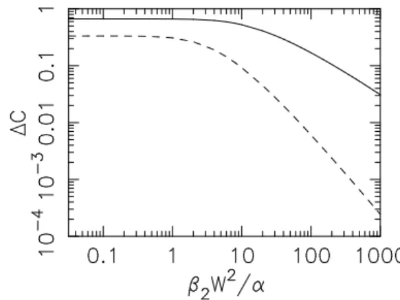
Fig. 2. The corrections to the channel capacity, ∆C1 and ∆C2, in
units ofW N2 γ2
P2 0α−
2
, shown as functions of|β2|W2/αin the
limitαd≫1,N≫1. The correction ∆C2 is represented by the
solid line, while ∆C1 corresponds to the dashed line. Note, that
∆C1, which describes the effect of the power leakage from the
bandwidth, is more strongly affected by the dispersion
Such scattering processes are suppressed, when the scat-tering leads to a subsantial change of the total momen-tumδκ[ω1, ω2→ω3, ω], so that the corresponding scatter-ing rate
S[ω1, ω2→ω3, ω] ∼ δ(ω1+ω2−ω3−ω)
1 + (δκ/κ0)2 (35) In the spirit of the uncertainty realtion,κ0∼1/Leff, where
Leff corresponds to the length of the concentration of the power of the signal in the fiber. For a small absorption coefficient α ≪ 1/d the distance Leff is of the order of the fiber length d, while in the opposite limit α≫ 1 the effective lengthLeff ≈1/α.
Using Eqn. (19), and the energy conservationω3=ω1+
ω2−ω, the momentum changeδκ[ω1, ω2→ω3, ω] can be expressed as
δκ = β2(ω−ω1) (ω−ω1) (36) Substituting (36) into (35), for the channel capacity loss due to the bandwidth power “leakage”, in the limitP0≫
PN, andαd≫1, we obtain ∆CP ∼ W∆P P ∼W γ2P2 0 α2 Z W dω1 Z W dω2 Z W dω3 × Z ω /∈W dω S[ω1, ω2→ω3, ω] = Wγ 2P2 0 α2 Z W dω1 Z W dω2 Z ω /∈W dω × 1 1 + (β2/α)2(ω−ω1)2(ω−ω2)2 (37) which in the appropriate limit is consistent with ∆C1.
In Fig. 2 we plot the dependence of ∆C1 on the dimen-sionless parameter β2W2/α. Since momentum change δκ
is proportional toβ2, the increase of the dispersion leads to a strong suppression of the power leakage from the band-width window, and of the corresponding correction to the channel capacity.
In a communication system with many “fiber-amplifier” units, the fiber nonlinearity leads not only to the mixing of the signals at different frequencies, but also to the mix-ing of the signal with the noise. Qualitatively, this would correspond to an effective enhancement of the noise power in the system, and therefore to a loss of the channel capac-ity. This effect is not present, when the system has only one “fiber-amplifier” link, which explains the appearance of the (N−1) factor in ∆C2 and ∆C3.
The effective noise enhancement is caused by the scat-tering processes, which involve a “signal photon” and a photon, produced due to spontaneous emission in one of the amplifiers. The total power of this extra noise can be expressed as ∆PN P0 ∼ γ 2P0PN α2 Z W dω1 Z W dω2 Z W dω3 Z W dω × S[ω1, ω2→ω3, ω] (38) The corresponding correction to the capacity
∆CN ∼ W ∆PN PN ∼Wγ 2P2 0 α2 Z W dω1 Z W dω2 Z W dω × 1 1 + (β2/α)2(ω−ω1)2(ω−ω2)2 (39) where we assumed αd ≫ 1. In this limit (39) is up to a constant factor identical to ∆C2.
The dependence of ∆C2onβ2W2/αis also shown in Fig.
2. Note, that ∆C2 also decreases with the increase of the dispersion, but more slowly than ∆C1. Since the scattering processes, which contribute to ∆C1, need to “move” one of the frequencies out of the bandwidth window, they gener-ally involve a substantial change of the total momentum, and are therefore more strongly affected by the dispersion. The two physical effects, described above, determine the fundamental limit to the bit rate for a fiber optics commu-nication system. As follows from our analysis (see Fig. 2), the relative contributions of ∆C1 and ∆C2, often referred to as the “four-wave mixing”, can be suppressed by choos-ing a fiber with a large dispersion, or when uschoos-ing a larger bandwidth.
In our analysis, we treated the whole available band-width as a single channel. As a result, the cross-phase modulation[2], which severely limits the performance of advanced wavelength-division multiplexing systems[6] (WDM), does not affect the channel capacity. The rea-son for this seemingly contradictory behaviour, is that in a WDM system, the “receiver”, tuned to a particular WDM channel, has no information on the signals at the other channels. Therefore, even in the absense of the “geniune” noise, the nonlinear interaction between different channels, leading to a change in the signal in any given channel, will be an effective noise source, thus limiting the communica-tion rate. This limit however is not fundamental, and can be overcome by using the whole bandwidth all together.
In conclusion, we developed a perturbative method for the calculation of the channel capacity for fiber optics com-munication systems. We obtained analytical expressions
for the corrections to the Shannon formula due to fiber nonlinearity. We have shown that, compared to the Shan-non limit, the actual channel capacity is substantially sup-pressed by the photon scattering processes, caused by the fiber nonlinearity.
Appendix
I. Perturbative Solution of the Propagation Equation
In this Appendix we describe the perturbative solutuion of the nonlinear equation (10) with the boundary condition
A(0, t) = Z
dω x(ω) exp (iωt) (40)
We representA(z, t) as a power series
A(z, t) = Z dωexpiωt−hα 2 +iκω i z ∞ X n=0 γℓ × Fℓ(z, ω) (41)
where κω is defined is (19). Substituting (41) into Eqns.
(10),(40), we obtain: (i) forℓ= 0 ∂F0(z, ω) ∂z = 0 (42) F0(0, ω) = x(ω) (43) (ii) forℓ6= 0 ∂Fℓ(z, ω) ∂z = i ℓ−1 X ℓ1,ℓ2,ℓ3=1 δℓ−1,ℓ1+ℓ2+ℓ3 Z dω1 Z dω2 × Fℓ1(z, ω1)Fℓ2(z, ω2)F ∗ ℓ3(z, ω1+ω1−ω) × exp [i(κω1+κω1−κω1+ω2−ω−κω)] (44) Fℓ(0, ω) = 0 (45)
whereδin the Kronekker’s delta-function.
For any ℓ, these equations reduce to linear first order differential equation, and can be solved straightforwardly. For example, the solutions for the first three terms in the anzats (41) are given by:
F0(z, ω) = x(ω) (46) F1(z, ω) = Z dω1 Z dω2 Fω ω1ω2x(ω1)x(ω2) × x∗(ω1+ω2−ω) (47) F2(z, ω) = Z dω1 Z dω2 Z dω3 Z dω¯ Gωω1ω2ω3m¯ × x∗(ω1)x∗(ω2)x(ω1+ω2−ω¯)x(ω3) × x(ω+ ¯ω−ω3) +Hωω1ω2ω3ω¯x(ω1)x(ω2)x(ω3) × x∗(ω1+ω2−ω¯)x∗(¯ω+ω3−ω)] (48) Here the functionsF,GandH are given by
Fω ω1ω2 = i 1−exp −αd−iφω ω1ω2d α+iφω ω1ω2
Gmω1ω2ω3ω¯ = − F ¯ ω ω1ω2 ∗ (Fω3 ωω¯) ∗ × (1−exp (−αd+iφω3 ωω¯d)) − Fω¯ ω1ω2 1 Fω¯ ω1ω2 + 1 Fω3 ωω¯ ∗ × 1−exp −2αd+ φωω¯1ω2+φ ω3 ωω¯ d Hωω1ω2ω3ω¯ = 2 F ¯ ω ω1ω2 Fωω¯m3 × 1−exp −αd−iφωωω¯ 3d − 2 Fω¯ ω1ω2 1 Fω¯ ω1ω2 +Fω1 ¯ ω ω3 ∗ × 1−exp −2αd−i φωω¯¯1ω2+φ ω ¯ ωω3 d where φωω1ω2 = (κω1+κω2−κω1+ω2−ω−κω)
II. The Perturbative Calculation of the Channel Capacity
In this Appendix, we describe the perturbative calcula-tion of the capacity of the simple nonlinear channel
y(ω) =x(ω) exp (iγφ[x(ω)]) +n(ω) (49) Hereφ[x] is an arbitrary real function, and the noisen(ω) is a Gaussian random variable:
pn[n(ω)] ∼ exp " −|n(ω)| 2 PN # (50) The fact, that the noise in this model is additive, implies that the conditional distribution p(y|x) is fixed, and de-fined by the noise distributionpn:
p(y|x) = pn[y−xexp (iγφ(x))] (51)
It is therefore straightforward to show, that the entropy
H[y|x] does not depend onγ:
H[y|x] = − Z dypn y−xeiγφ(x) ×loghpn y−xeiγφ(x)i = − Z dzpn(z) log [pn(z)] = log [2πePN] (52)
In order to calculate the entropy H[y], we represent the output distribution as a power series in γ:
py(y) = p0y(y) " 1 + ∞ X n=1 p(yn)(y) # (53) wherep0
y(y) is the “unperturbed”, Gaussian distribution
p0y(y) = 1 π(P0+PN) exp − |y| 2 P0+PN ! (54)
corresponding to the linear channely=x+n. Substituting (53) into the definition of the entropy Hy, Eq. (5), we
obtain: Hy = log [2πe(P0+PN)]− 1 2 Z p(1)y (y) 2 p0y(y) + 1 P0+PN Z dy|y|2py(y) − Z dy|y|2p0y(y) (55) The second term in Eq. (55), (1/2)R
p(1)y (y)2p0y(y),
repre-sents the difference of the output distribution from Gaus-sian, and corresponds to the contribution ∆Hyin Eq. (20).
Note, that in the second order in nonlinearity the devia-tions of the output distribution from Gaussian lead to a
decreaseof capacity.
The third term,
(1/(P0+PN))
hR
dy|y|2py(y)−Rdy|y|2p0y(y)
i
, is propor-tional to the change of the output power, R
dy|y|2py(y),
due to nonlinearity, and corresponds to ∆C1 in Eq. (20). Generally, the nonlinearity leads to energy exchange tween different degrees of freedom in the channel (e.g. be-tween different frequencies), and to the power leakage out of the bandwidth window. However, for the specific (nad non-generic) example, chosen in the present Appendix, this exchange is absent, since the output power
h|y|2i = h|x|2i+h|n|2i=P0+PN (56)
does not depend on the nonlinearity.
Substituting (56) in Eq. (55), and using Eq. (52), for the mutual informationRwe obtain:
R = log 1 + P0 PN −1 2 Z p(1) y (y) 2 p0 y(y) (57)
As immediately follows from Eq. (57), the channel capac-ity, equal to the maximum of the mutual information, is given by the Shannon formula (1), and is achieved when
p(1)
y (y) = 0 (58)
The next step is to calculate theinputdistribution
px(x) = p0x(x) " 1 + ∞ X n=1 p(xn)(x) # (59) corresponding to (58). The general relation between the input and the output distributions is defined by the condi-tional distributionp(y|x):
py(y) =
Z
dx p(y|x) px(x) (60)
and, considered as an equation forp(x), is a Fredholm in-tergal equation of the first kind. Note however, that since Eq. (58) represents not the whole output distribution, but only it’s first order term p(1)y (y), we can expand Eq. (60)
and keep only the terms up to the first order in γ. We obtain: Z dx p(y|x)|γ=0 p0x(x) p(1)x (x) + Z dx ∂ ∂γp(y|x) γ=0 p0x(x) = 0, (61)
Substituting here the conditional distribution from Eq. (51), we obtain: Z dx pn(y−x)p0x(x)p1(x) = i PN × Z dx pn(y−x)p0x(x)φ(x) (x∗y−y∗x), (62)
Using the identity
ypn(y−x) = x+PN ∂ ∂x∗ pn(y−x), (63)
and integrating by parts, we can represent the right hand side of (62) as follows: i Z dx pn(y−x)p0x(x) i PNφ(x) (x ∗y−y∗x) = i Z dx pn(y−x)p0x(x) x∗∂φ(x) ∂x∗ −x ∂φ(x) ∂x (64) Therefore, as follows from Eqns. (62) and (64), the input distribution p(1)x (x) = i x∗∂φ(x) ∂x∗ −x ∂φ(x) ∂x (65) This procedure can be followed up for all orders inγ. By a direct calculation, it is straightforward to show, that the channel capacity is represented by the Shannon result (1), which is achieved when for anyn >1
(
p(xn)(x) = 0
p(yn)(y) = 0
(66) Subsitituting (66) and (65) into Eq. (59), for the input distibution we finally obtain:
px(x) = 1 πP0 1 +iγ x∗∂φ(x) ∂x∗ −x ∂φ(x) ∂x × exp " −|x| 2 P0 # (67) with the corresponding channel capacity
C = Wlog 1 + P0 PN (68) This result has a simple physical meaning. When the in-put distribution is organized in such a way, that the quan-tityz=xexp (iγφ(x)) has the Gaussian distribution, then,
considering z as input, the communication channel be-comes linear: y=z+n, and the channel capacity is there-fore given by the Shannon formula (1),(68). The corre-sponding input distribution is then defined by the Jacobian of the transformation fromx≡xR+ixI to z≡zR+izI,
∂(zR, zI)/∂(xR, xI) (note, thatxR,xI,zR,zI are defined
asrealvariables): px(x) = 1 πP0 ∂(zR, zI) ∂(xR, xI)exp " − x2R+x2I 2 P0 # (69) which reduces to the distribution (67), since
∂(zR, zI) ∂(xR, xI) = 1 +γxR ∂φ(xR, xI) ∂xI −γxI ∂φ(xR, xI) ∂xR ≡ 1 +iγx∗∂φ(x, x ∗) ∂x∗ −iγx ∂φ(x, x∗) ∂x (70)
This result should be contrasted to the so called “Gaus-sian estimate” of the channel capacity[7]. In the latter appoach, the information channel is described by thejoint Gaussiandistribution P(xω, yω)∼exp −[x∗ ω y∗ω]A xω yω (71) where A = hx∗ ωxωi hx∗ωyωi hy∗ ωxωi hy∗ωyωi −1 (72) The channel capacity is then estimated as the mutual in-formation, corresponding to the distribution (71):
CG= Z dωlog hx∗ ωxωihyω∗yωi hx∗ ωxωihyω∗yωi − hx∗ωyωihyω∗xωi (73) Under the constraint of the fixed input powerR
dωh|xω|2i,
the estimate (73) was shown[7] to give the low bound to the channel capacity.
For the model channel considered in the present Ap-pendix, the “Gaussian estimate” yields an expression, dif-ferentfrom the Shannon result. For example, whenφ(x) =
|x|2, we obtain CG = −Wlog " 1− P0 (P0+PN) (1 +γ2P02) 2 # = Wlog 1 + P0 PN −2W γ2P2 0 P0 PN +O γ4 (74) which, as expected, is smaller that the actual channel ca-pacity (68). Note, that the difference between the exact channel capacity and the Gaussian estimate
δC ≡ C−CG=Wlog " 1 + P0 PN 1− 1 (1 +γ2P2 0) 2 !# = 2W γ2P2 0 P0 PN +O γ4 (75)
is not merely a constant scale factor, but a nontrivial func-tion of the signal to noise ratio, and the nonlinerity.
Even when the input distribution is Gaussian, like e.g. when the phaseφ depends onxvia the “power” |x|2, the Gaussian Estimate does not yield the exact result. The reason for this behaviour is that the joint Gaussian distri-bution does not correctly reproduce theconditional distri-bution p(y|x).
For an essentially noinlinear system (e.g. a fiber op-tics communication channel), there is generally very little
aprioriknowledge about the parametric dependence of the Channel Capacity on the signal to noise ratio and other system parameters. In this case, the Gaussian Estimate for the channel capacity can be (should be?) viewed as a very unreliable method, as there is no way to separate it’s artefacts from the actual behaviour of the channel capacity.
References
[1] C. E. Shannon,A Mathematical Theory of Communication. The Bell System Technical Journal vol 27, pp. 379 - 423, 623-656. 1948.
[2] G.P.Agrawal, Nonlinear Fiber Optics, Academic Press, San Diego, 1995.
[3] R.K.Dodd, J.C.Eilbeck, J.D.Gibbon, and H.C.Morris, Solitons and Nonlinear Wave Equations, Academic Press, New York, 1984.
[4] G. L. Lamb, Jr.,Elements of Soliton Theory, Wiley, New York, 1980.
[5] J. P. Gordon and L. F. Mollenauer,Phase noise in photonic com-munication systems using linear amplifiers. Optics Letters, vol. 23, pp. 1351-1353. Dec. 1990.
[6] G. P. Agrawal,Fiber-Optic Communication Systems, John Wiley and Sons, New York, 1997.