Lighting Control System
Catalog
Lighting Control System
Introduction ... Page 4 POWERLINK AS Systems
Overview ... Page 5 Soft Split System ... Page 6 LV Switching System ... Page 6 Time Clock System ... Page 6 System Components (exploded & applied views) ... Page 8 Electronic Components
QO(B)-AS and EHB-AS Circuit Breakers ... Page 9 Control Bus Strips ... Page 15 Power Interface Module ... Page 17 Class 2 Barrier Kit ... Page 19 Control Modules ... Page 20 Panelboards
General Information ... Page 27 Series Ratings ... Page 28 Dimensions ... Page 29 Accessories
Desktop Power Supply ... Page 35 Input Expansion Cabinet ... Page 36 Network Options
General Information ... Page 38 LonWorks Gateway ... Page 39 Software
Overview ... Page 40 Features (PLK/CMS) ... Page 41 Power Management Services ... Page 42 Compliance Certification
Codes and Standards ... Page 43 Year 2000 Compliance ... Page 44 Suggested Specifications ... Page 45
The POWERLINK AS lighting control system combines remote switching capabilities and thermal-magnetic overcurrent protection in standard Square D NQOD and NEHB panelboards. The POWERLINK AS system offers the capability to control lighting and other loads to preset time schedules or from external control devices such as wall switches, occupancy sensors, or building management systems. POWERLINK panelboards can also be networked together, set up, and monitored from a remote location.
Standard components of the POWERLINK AS system include remotely operated circuit breakers, control bus strips, a power interface module, and Class 2 barrier kit. Optional network and display components include a control module with an internal time clock, Windows®
-based software for remote setup and monitoring, and various components for remote communications.
The POWERLINK AS system features modular “plug and play” component construction that simplifies design, specifications, and installation. It minimizes wiring and wiring errors, thereby reducing installation time and costs, while enhancing reliability and offering expanded functionality. The modular design also eliminates the need for separate interface cabinets, interposing relays, external control voltage circuits, external time clocks, or contactor devices typically associated with lighting control systems. This is made possible by the integration of remote power switch-ing capability, thermal-magnetic circuit breakers, an internal power supply, communications, an optional internal time clock, and control functions in a single panelboard.
The POWERLINK AS system can be configured to meet specific needs for remote power switching and branch circuit overcurrent protection. This makes it ideal for a variety of energy and load management applications. It allows building owners, operators, and plant managers to efficiently manage lighting, as well as many other types of electrical loads, including:
• Displays • Electric strip heaters • Interior/exterior signage • Exhaust fans • Water heaters • Power drops • Water coolers • Appliances
• HVAC units • Audio/video equipment
POWERLINK AS Panelboard
Introduction
POWERLINK AS systems provide the easiest means possible of adding automatic control of electrical power—for lighting control and other applications—to new or existing buildings. Controlling electrical loads—turning them off during unoccupied periods—conserves energy, saves money, and helps the environment. This is not only cost effective, but is often required by federal and state laws in new or renovated buildings. POWERLINK AS systems use innovative circuit breaker technology, and fit into conventional panelboard enclosures. Because no additional enclosures are needed and existing conduits remain undisturbed, POWERLINK AS systems are easily retrofitted into existing facilities and typically have a lower installed cost than conventional contactor or
relay-Saving Time and Money
POWERLINK AS systems are substantially less expensive to design and install compared to traditional relay or contactor technology. Design and layout of the POWERLINK AS system are as simple as those of any other panelboard.
The POWERLINK AS system can do many things that contactors cannot do, even with elaborate control wiring and auxiliary components. POWERLINK AS capabilities include:
• Independent branch circuit control is easy to set and change through software settings.
• 42-channel time clock with seven-day repeating schedule and 365-day calendar, including 32 holiday periods, daylight savings adjustment, and astronomical sunrise/sunset capabilities. In short, a full-featured time clock at a very low price.
• Automatic time off sweeps—very effective for saving energy.
• Central monitoring and control provided by the communications network, which can be industry standard RS-485 or LONWORKS®, or both.
• Blink notice—lets you know when lights are about to turn off. • Low voltage Class 2 wiring used for switch inputs—usually does not
require conduit and is easy to move.
• Easy to change inputs and timed event schedules—a plus for retailers and commercial facilities that frequently change their facility layouts. Recon-figuration is done in minutes, rather than by time-consuming rewiring. • Set up either at the front panel or remotely over the RS-485 network. • Advanced system features, such as telephone override and master
switch override and configured input timers. Features like these are difficult and expensive to hard-wire with contactors.
• Downloadable firmware for new features.
The modular components of the POWERLINK AS system simply plug into Square D panelboards for ease of installation and operation. There are no wiring harnesses or pigtails. Branch circuit conductors do not have to be routed through other enclosures.
Overview
1 2 3 4 5 6 7 8 57 58 59 60 61 62 63 64 + - C + - C + - C + - C + - C + - C + - C + - CTX RXSH IN-IN OUT- OUT+ +SH
EXP RS-485 (COMMS)
•
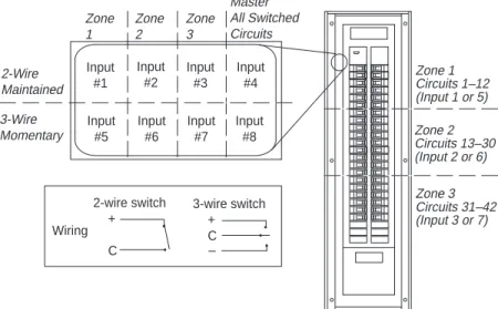
LED 2-Wire Maintained Master All Switched Circuits Zone 3 Zone 2 Zone 1 3-Wire Momentary Zone 3 Circuits 31–42 (Input 3 or 7) Zone 1 Circuits 1–12 (Input 1 or 5) Zone 2 Circuits 13–30 (Input 2 or 6)Soft-Split System (no control module)
❏ Factory pre-configured—No field setup is required
❏ External devices control up to three pre-con-figured zones and 42 circuits
❏ All breakers in the zone will be controlled by the pre-mapped input
❏ Master input controls all switched circuits
❏ Functionality of a split bus panelboard or contactor system—but “soft” splits can be changed with a control module
❏ External control wiring connects in power interface module
❏ Standard circuit breakers can be intermixed with remotely operated breakers
Low Voltage Matrix Switching System
(simple-input based control)
❏ All POWERLINK AS systems can perform low voltage matrix switching
❏ Each system supports up to 16 low voltage inputs, expandable to 64 inputs
❏ Mapping of inputs to switch specific branch circuits is performed using a control module
❏ Any circuit can be logically connected (mapped) to any input
❏ Easy setup with graphic control module— reconfiguring to accommodate facility changes is easy and involves no rewiring
❏ After programming, the control module can be removed, and the POWERLINK AS systems will continue to switch circuits from input connections
Time Clock System using control module
❏ Same features as low voltage matrix switching❏ Individual schedules for each circuit or zone
❏ 7-day repeating schedules
❏ Special holiday schedules
❏ 365-day calendar
❏ Configure up to 256 events
❏ Sunrise/sunset astronomical clock eliminates the need for photocells
❏ Blink notice
❏ Daylight savings time
Control Circuits 1 External Inputs 2 3 4 5 10...18 19...42 2 5 1 3 4 On On Off
Table 1 Sample Control Map
On
Off Off Off Off Off Off
On On
AS42C-T
AS42CM-T
On On On On Input #1 Input #2 Input #5 Input #6 Input #3 Input #4 Input #7 Input #8 Wiring 2-wire switch + C 3-wire switch + C • • • • • –POWERLINK AS systems support a wide variety of network options to allow remote communications with the POWERLINK panel either via a workstation or from a third-party building automation system.
Network Topology and Compatibility
Network options for the POWERLINK AS system are as follows: RS-485
• An optional RS-485 network communications port for integration into a power monitoring and control system.
• Up to 32 panelboards can be connected on a multi-drop network directly to a personal computer via an RS-232/485 port.
• To optimize system performance with multi-drop networks, the
POWERLINK AS system can communicate over the Square D SY/NET network. This network supports communications speeds up to 500K Baud, distances up to 15,000 feet, and practically limitless device connections.
LonWorks
• Takes advantage of the latest industry standard technology to provide high-speed, peer-to-peer communications.
• Allows the POWERLINK AS system to operate on the same network as other devices supporting the LonWorks protocol.
• POWERLINK AS panelboards are fully LonMark compliant.
• Adds capabilities to the POWERLINK AS system, such as the ability to create global zones or shared inputs.
• Provides vast flexibility in configuring unique control solutions. Examples include the following:
–An input switch in one panel can control circuit breakers in any panel on the network.
–A time-of-day control module in one panel can control circuit breakers in many panels.
–Third party I/O and software can interface directly with POWERLINK AS inputs and breakers.
Ethernet
• Allows the POWERLINK AS system to communicate on new or existing networks
• Provides high speed, high bandwidth communication
Powerful Software Solutions
Square D offers a full line of simple to advanced, system-wide WINDOWS®-based software packages. POWERLINK AS application
software automatically integrates real-time panelboard and system information into organized and usable formats.
Application Engineering Services
The Square D Power Management Operation Engineering Services Group provides a complete range of commercial and industrial facility design and
Overview
Control Bus Strips Power Interface Module Class 2 Barrier Kit Graphical Control Module with Clock
Components
X
X
X
X
X
X
X
*X
X
X
X
* Only one graphical control module is required to
Table 2
POWERLINK AS Systems — Components
POWERLINK System Types
Soft-Split System
LV Matrix Switching System Time Clock System
Class 2 Barrier Kit
Power Interface Module
Control Module with Local Display
Standard Circuit Breakers Low Voltage External Control Device Input Compartment Main Lug Compartment (225 A Max.) 1-, 2-, and 3-Pole Remote Control Circuit Breakers
Control Bus Strips (Furnished in Pairs)
NQOD/NEHB Panel (225 A max. interior) Class 2 Barrier Kit
QO(B)-AS or EHB-AS Remotely Operated Circuit Breakers Power Interface Module
(standard and network versions)
Control Module (local display optional)
Control Bus Strips (furnished in pairs)
Figure 2—POWERLINK AS System (Exploded View of Components)
Exploded View
The diagram to the right shows an exploded view of the POWERLINK AS system. The system components feature several advantages over components of conventional systems: • Modular design • Simple and quick installation
• All components snap into place (plug and play)
• No wiring harnesses or pigtails
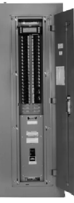
Complete System
The photo to the right shows a complete NQOD panelboard system.
POWERLINK AS systems use standard NQOD and NEHB panelboards as foundations. All enclosures, interiors, deadfronts, and accessories are standard off-the-shelf items. The POWERLINK AS system components are discussed in detail in the following sections.
Remotely Operated Circuit Breakers
• Overcurrent protection. POWERLINK AS circuit breakers provide the
same overload and short circuit protection as standard QO(B) and EHB circuit breakers.
• High interrupting. Series connected ratings up to 200,000 rms
symmetri-cal amperes with integral or remote mounted main breakers.
• Multi-pole switching. Single-, two-, and three-pole circuits can be switched.
• Position indication. An integral on/off/trip status flag indicates the actual
state of breaker contacts.
• Up to 30 amperes. 15, 20, and 30 ampere ratings are available.
• Rugged contacts. POWERLINK AS circuit breakers can handle the high
loads found in buildings today. They are rated for full life with inductive loads (0.8 power factor). They are also rated for HACR (heating, air conditioning, and refrigeration) service, as well as HID (high intensity discharge) lighting loads.
• Switch duty rated. 15 A and 20 A circuit breakers are SWD (switch duty)
rated for use with 120 V fluorescent lighting loads.
• Long life. At 200,000 electrical load operations, they last up to six times
longer than other common power switching devices.
• Manual override. Each circuit breaker has a mechanical override that has
priority over remote operation. The circuit can be turned off or on in a crisis. • Plug and play control connector. Wiring mistakes are eliminated by
modular connectors. There is no exposed wiring.
Principles of Operation
The core of a POWERLINK AS circuit breaker is the highly effective Square D trip mechanism. A 24 Vdc motor, along with a drive train and linkage, provides remote operation capability. This motor is located in the left pole of the 2-pole circuit breaker and the center pole of the 3-pole circuit breaker.
When the circuit breaker handle is in the on position, the motor and drive train can open and close the contacts. When the handle is in the off position or the circuit breakers is tripped, the contacts cannot be closed remotely. The auto/manual switching mode selector on the front of the circuit breaker provides mechanical override capability. In manual mode, the motor drive train is disconnected from the contacts. The circuit breaker handle then operates the contacts like a conventional circuit breaker.
A sensing device determines the presence or absence of voltage on the loadside terminal, and reports circuit breaker contact position back to the control system. Thus, a true-positive-closed-loop feedback of actual contact status is achieved.
POWERLINK AS circuit breakers are an integral part of the POWERLINK lighting control system. These compact devices perform both overcurrent protection and remote switching functions. Circuit breakers feature rugged contacts rated for 200,000 load operations and can be series rated for use with systems capable of providing 200,000 rms symmetrical fault current.
Features
General
POWERLINK AS remotely operated, thermal-magnetic circuit breakers (hereafter referred to as POWERLINK AS circuit breakers) are designed to provide remote switching and overcurrent protection on ac voltage systems. They are available in 1-, 2-, and 3-pole construction. The 2- and 3-pole circuit breakers are common trip. An overcurrent condition on any given pole of the circuit breaker will cause all poles of the circuit breaker to open. POWERLINK AS circuit breakers are UL Listed and CSA Certified. They are manufactured and tested according to the following standards: • UL Standard 489
• NEMA Standard AB-1-1986
• Canadian Standards Association (CSA) Standard 22.5 (QO(B) only) • Federal Specification W-C-375B/GEN, Class 11a, 11b; 12a, 12b; and 13a, 13b • NOM 117 (pending final testing)
Tripping System
POWERLINK AS circuit breakers have a permanent trip unit that contains a factory preset thermal (overload) trip element and a magnetic (short circuit) trip element in each pole. The thermal trip element is true rms sensing and is calibrated to carry the continuous current rating of the breaker at 40°C (140°F) free air ambient temperature. In accordance with the National Electrical Code, POWERLINK AS circuit breakers are intended to be applied at up to 80 percent of their continuous current rating.
Operating Mechanism
POWERLINK AS circuit breakers have an over-center toggle mechanism that provides quick-make, quick-break operation and Square D’s unique VISI-TRIP® circuit breaker trip indicator. The operating mechanism is
trip-free. This means the circuit breaker will trip even though the operating handle may be restricted to the ON position. Without any restrictions, the operating handle moves to a position between ON and OFF when the circuit breaker is tripped. An internal cross-bar provides common tripping of all poles on 2- and 3-pole POWERLINK AS circuit breakers.
Circuit Breaker Status Indicator with VISI-TRIP
POWERLINK AS circuit breakers are equipped with Square D’s unique VISI-TRIP circuit breaker trip indicator. The indicator window displays one of three colors to show circuit breaker contact status.
Indicator Color Circuit Breaker Contact Status
White Circuit breaker contacts are closed Green Circuit breaker contacts are open
Red VISI-TRIP indicator, circuit breaker is tripped Load Terminations
All load lugs are UL Listed to accept solid or stranded and copper or alumi-num conductors. Lugs are suitable for use with wire rated for 75°C (sized according to the 1993 National Electrical Code 75°C temperature rating) QO(B)-AS circuit breakers are rated for 60°/75°C, and EHB-AS circuit breakers are rated for 75°C.
VISI-TRIP indicator Switching mode selector
Remotely Operated Circuit Breakers
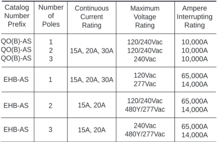
Table 1 Ratings for POWERLINK AS Circuit Breakers Catalog Number Prefix QO(B) QO(B) QO(B) EHB EHB EHB Number of Poles 1 2 3 1 2 3 Voltage Rating 120/240Vac 120/240Vac 240Vac 120Vac 277Vac 120/240Vac 480Y/277Vac 240Vac 480Y/277Vac Continuous Current Rating 15A, 20A, 30A 15A, 20A, 30A 15A, 20A, 30A 15A, 20A, 30A
15A, 20A 15A, 20A Ampere Interrupting Rating 10,000A 10,000A 10,000A 65,000A 14,000A 65,000A 14,000A 65,000A 14,000A Maximum Voltage Rating 120/240Vac 120/240Vac 240Vac 120Vac 277Vac 120/240Vac 480Y/277Vac 240Vac 480Y/277Vac Continuous Current Rating
15A, 20A, 30A
15A, 20A, 30A
15A, 20A 15A, 20A 1 2 3 EHB-AS EHB-AS EHB-AS 1 2 3
Ratings for POWERLINK AS Circuit Breakers
The following POWERLINK AS circuit breaker ratings must meet or exceed the parameters of the electrical system on which the breakers are used.
Continuous Current Ratings
POWERLINK AS circuit breakers have continuous current ampere ratings, as established by the 1993 NEC, Paragraph 240-6a, for 15A, 20A, and 30A devices.
POWERLINK AS circuit breakers are to be applied in accordance with the NEC for 80 percent continuous current ratings in the intended enclosure. The continuous current ratings is indicated on the operating handle of each circuit breaker.
Interrupting Ratings
POWERLINK AS circuit breakers have interrupting ratings for each specific type: QO(B) or EHB, as shown in Table 3. The ampere interrupting rating of a circuit breaker is the highest current at rated voltage that the circuit breaker is intended to interrupt under standard test conditions and is expressed in rms symmetical amperes. The interrupting rating is stamped into each POWERLINK AS circuit breaker case for each voltage rating. POWERLINK AS circuit breakers have series connected ratings, like standard QO(B) and EHB breakers. The series connected ratings apply to either an integral main located in the same enclosure, or a remote main located in a separate enclosure. For more information on NQOD and NEHB panelboard series ratings, see page 28.
Table 3
UL Listed Interrupting Ratings for POWERLINK AS Circuit Breakers
QO(B)-AS QO(B)-AS QO(B)-AS
Frequency Rating
The rated frequency for POWERLINK AS circuit breakers is 50/60Hz. Applying POWERLINK AS circuit breakers at frequencies above or below the rated frequency may possibly damage the circuit breaker electronic components or system electronics.
UL HACR Rating
All POWERLINK AS circuit breakers are UL Listed for use with heating, air
UL HID Rating
All POWERLINK AS circuit breakers have a UL Listed rating for use with high intensity discharge lighting. These lighting systems, which include high pressure sodium, metal halide, and mercury vapor, have inherently high inrush current characteristics, which require circuit breakers rated for such applications.
UL Switching Duty Rating
POWERLINK QO(B)-AS and EHB-AS circuit breakers are UL Listed for Switching Duty (SWD), making them suitable for switching 120Vac fluores-cent lighting loads. This switching duty rating applies only to QO(B)-AS and EHB-AS 15A and 20A circuit breakers in 1-, 2-, and 3-pole versions.
Switching Mode Selector Switch
On the front of POWERLINK AS circuit breakers is a switching mode selector switch that places the circuit breaker in either AUTO or MANUAL switching mode. When the switching mode selector is in the down position (or AUTO mode) and the circuit breaker operating handle is in the ON position, the circuit breaker contacts may be remotely opened or closed via the internal 24Vdc motor and circuit breaker electronics. If the switching mode selector is in the out position (or MANUAL mode), the remote switching mechanism is disengaged, and the circuit breaker contacts default to the position as indicated by the circuit breaker operating handle. If the switching mode selector is initially in MANUAL mode, then depressed into the AUTO mode, the circuit breaker contacts default to the last state (open or closed) issued by the POWERLINK AS system control module. In the MANUAL mode, all POWERLINK AS circuit breakers are physically disengaged from the remote mechanism, which causes them to disregard signals from the POWERLINK AS system control module and operate the same as standard circuit breakers. When the circuit breaker operating handle is in the OFF or TRIPPED position and the switching mode selector is in either the AUTO or MANUAL mode, the circuit breaker cannot be remotely turned on or reset. When tripped, the circuit breaker must be reset using the circuit breaker operating handle.
The following table describes switching conditions of POWERLINK AS circuit breakers. Switching Mode Selection Position AUTO or MANUAL AUTO AUTO AUTO AUTO MANUAL MANUAL AUTO or MANUAL
CIRCUIT BREAKER INITIAL STATUS Circuit Breaker Handle Position OFF ON ON ON ON ON ON TRIPPED Initial Position of Circuit Breaker Contacts OPEN OPEN OPEN CLOSED CLOSED OPEN CLOSED OPEN ACTION Input Command from Controller ON or OFF OFF ON ON OFF ON or OFF ON or OFF ON or OFF
CIRCUIT BREAKER FINAL STATUS Final Position of Circuit Breaker Contacts OPEN OPEN CLOSED CLOSED OPEN CLOSED CLOSED OPEN Resulting Action None None Load ON None Load OFF Load ON None None
Remotely Operated Circuit Breakers
Table 5
Calculated Electrical Endurance (Years)
QO(B)-AS and EHB-AS Circuit Breakers
Number of
Estimated
Operations per Day
Endurance in Years
18
30
22
25
27
20
37
15
55
10
110
5
548
1
Note: One operation is defined as either from closed to open to closed, or from
open to closed to open. Numbers are calculated estimates, based on operating 365 days per year.
Construction Standards for POWERLINK AS Circuit Breakers
The POWERLINK AS system uses a remotely operated, thermal-magnetic circuit breaker to provide remote switching and overcurrent protection. For more detailed information on Square D thermal-magnetic circuit breakers, refer to the Distribution Product Catalog Class 601, Thermal-Magnetic/ Magnetic Only Molded Case Circuit Breakers.
Remote Circuit Breaker Endurance
QO(B)-AS and EHB-AS circuit breakers have an electrical life of 200,000 remote operations (at 80% load and 0.8 power factor). The number of years the circuit breakers yield based on the number of operations per day.
Ampere Rating One-Pole 120/240Vac - 10,000 AIR Plug-on Catalog No. Bolt-on Catalog No. Two-Pole 120/240Vac - 10,000 AIR Three-Pole
240Vac - 10,000 AIR Lug Wore
Size▼ Plug-on Catalog No. Bolt-on Catalog No. Plug-on Catalog No. Bolt-on Catalog No. 15 20 30 QO115AS ●▲ QO120AS ●▲ OQ130 ● QOB115AS ●▲ QOB120AS ●▲ OQB130 ● QO215AS ●▲ QO220AS ●▲ OQ230 ● QOB215AS ●▲ QOB220AS ●▲ OQB230 ● QO315AS ●▲ QO320AS ●▲ OQ330 ● QOB315AS ●▲ QOB320AS ●▲ OQB330 ● (1) #12-8 Al (1) or (2) #14-10 Cu QO/QOB-AS Plug-on or Bolt-on Remote Controlled Circuit Breakers—UL Listed
All are UL Listed as HACR type for use with air conditioning, heating, and refrigeration equipment having motor group combinations and marked for use with HACR type circuit breakers.
▲ UL Listed as SWD (switching duty) rated. Suitable for switching 120Vac fluorescent lighting loads. ● HID rated for use with high intensity discharge lighting systems.
▼ Suitable for use with 60°C or 75°C conductors. POWERLINK QO(B)-AS Circuit Breakers UL Listed Mechanical Accessories—Class 690 Handle Accessories
Handle Lock-off
Handle Padlock Attachment
Breaker Prefix Number of Poles Catalog Number
QO(B) 1, 2, 3 HLO1 QO(B) 1, 2, 3 QOASPA Ampere Rating One-Pole 277Vac - 14,000 AIR 120Vac - 65,000 AIR Catalog No. Two-Pole 480Y/277Vac - 14,000 AIR 120/240Vac - 65,000 AIR Three-Pole 480Y/277Vac - 14,000 AIR
240Vac - 65,000 AIR Lug Wore
Size▼
Catalog No. Catalog No.
15 20 30 EHB14015AS ●▲ EHB14020AS ●▲ EHB14030AS ● EHB24015AS ●▲ EHB24020AS ●▲ EHB34015AS ●▲ EHB34020AS ●▲ (1) or (2) #14-10 Cu(1) #12-8 Al EHB-AS Bolt-on Remote Controlled Circuit Breakers—UL Listed
All are UL Listed as HACR type for use with air conditioning, heating, and refrigeration equipment having motor group combinations and marked for use with HACR type circuit breakers.
▲ UL Listed as SWD (switching duty) rated. Suitable for switching 120Vac fluorescent lighting loads. ● HID rated for use with high intensity discharge lighting systems.
▼ Suitable for use with 75°C conductors. POWERLINK EHB-AS Circuit Breakers
UL Listed Mechanical Accessories—Class 690 Handle Accessories
Handle Lock-off
Handle Padlock Attachment
Breaker Prefix Number of Poles Catalog Number
EHB 1, 2, 3 HLO1 EHB 1, 2, 3 EHASPA ire ire
•
•
•
•
•
•
QO130AS QOB130AS QO230AS QOB230AS QO330AS QOB330AS
SELECTION DATA
UL Listed as HID rated for use with high intensity discharge lighting systems. UL Listed as HID rated for use with high intensity discharge lighting systems.
Remotely Operated Circuit Breakers
Remotely Operated
Control Bus Strips
• Internal interconnect wiring meets NEC and UL requirements for Class 1 control circuits.
• Control bus strips meet NEC and UL requirements for maximum allow-able gutter fill.
• Installation is simplified since control bus strips reside on panelboard interior mounting channels without fasteners.
• Alignment tool is included to speed installation. Control bus alignment tool holds two control bus strips in place on panelboard interior mounting channel, while POWERLINK circuit breakers are attached to interior. Tool may be removed after first circuit breakers are installed.
• Top and bottom 25-pin connectors provide flexibility in mounting power interface modules.
• External Class 1 control wiring is eliminated between circuit breakers and the power interface module, reducing installation time.
• 6-pin connectors provide secure plug-in connections for circuit breakers and ensure that proper connections are made.
• Each connector comes with a cover to protect the connection until needed.
• Furnished in bi-directional identical pairs. No “left” or “right” devices to cause installation problems.
Features
Control bus strips, used in conjunction with the other POWERLINK AS modular components, eliminate external control wiring between POWERLINK AS circuit breakers and the power interface module, which simplifies installation and troubleshooting procedures.
The POWERLINK AS system uses NQOD-ASB and NEHB-ASB control bus strips. The control bus strips provide interconnect wiring between POWERLINK AS circuit breakers and the power interface module. Specifi-cally, they conduct 24Vdc switching power and control signals from the power interface to switch individual circuit breakers, and report circuit breaker status back to the control module.
Type NQOD-ASB Control Bus
for NQOD Panelboards
Max. No. of Control Circuits 14 24 36 42 Required Panel Space (Interior) 20 Poles 30 Poles 42 Poles 54 Poles Control Bus Catalog Number NQOD214ASB NQOD224ASB NQOD236ASB NQOD242ASB
Single Phase 100A and 225A
Max. No. of Control Circuits 18 24 36 42 Required Panel Space (Interior) 20 Poles 30 Poles 42 Poles 54 Poles Control Bus Catalog Number NQOD218ASB NQOD224ASB NQOD236ASB NQOD242ASB
Three Phase 100A and 225A
Max. No. of Control Circuits 12 24 36 42 Required Panel Space (Interior) 20 Poles 30 Poles 42 Poles 54 Poles Control Bus Catalog Number NEHB412ASB NEHB242ASB NEHB436ASB NEHB442ASB
Three Phase 100A and 225A
Type NEHB-ASB Control Bus
for NEHB Panelboards
Control bus type NQOD-ASB is not suitable for use with NQOD 400A or 600A panels, NQOD column-width panels, panelboard interiors with 14” wide enclosures, or QO load centers.
Control bus type NEHB-ASB is not suitable for use with NEHB 400A, 600A, or NEHB column-width panels.
SELECTION DATA
NEHB Control Bus (furnished in pairs)
Power Interface Module
• One power supply furnishes 24Vdc power for remote circuit breaker switching and 5Vdc power for the control module system electronics. • Sequencing operation with programmable stagger delay eliminates
voltage sags when multiple circuit breakers are switched as a group. • On-board EEPROM retains input map, even in the event of a power
outage.
• Input terminal board accepts up to 16 external dry contact inputs with the following characteristics:
– 2-wire maintained (16) – 2-wire momentary (16) – 3-wire momentary (8)
• An RS-232 port provides the means for interfacing to an optional input expansion cabinet, LonWorks gateway, or remote dial-up connections. • RS-485 network option for connection to SY/LINK networks.
• Module can be mounted at either the top or bottom of the panelboard interior.
• Plugs directly to the panelboard interior; occupies only six pole spaces. • Only one wire to connect: the neutral wire.
The power interface module provides voltage sources for POWERLINK AS circuit breakers and system electronics, and reports the status to the control module. In addition, the module contains input and communications terminations for connecting to external control devices.
Features
The power interface module has capability for up to 16 two-wire inputs, 8 three-wire inputs, or a combination of these types of inputs. These are numbered 1 through 8 [plus (+) to common (C)] and 57 through 64 [minus (-) to common (C)] on the interface module. Inputs 9 through 56 are available when the expansion cabinet is used.
1 2 3 4 5 6 7 8 57 58 59 60 61 62 63 64 + - C + - C + - C + - C + - C + - C + - C + - C
TX RXSH IN-IN OUT- OUT+ +SH
EXP RS-485 (COMMS)
•
LED Wiring 2-wire switch + C 3-wire switch + C • • • • • – 1 2 3 4 5 6 7 8 57 58 59 60 61 62 63 64 + - C + - C + - C + - C + - C + - C + - C + - CTX RXSH IN-IN OUT- OUT+ +SH
EXP RS-485 (COMMS)
•
LEDInput Terminal Compartment Power Interface Module
(Standard)
Input Terminal Compartment Power Interface Module
(Network)
Wiring Diagram
Power Interface Module
SPECIFICATIONS
Operating Voltage:
NQOD242ASP(N) &
Max. Operating Range
NEHB242ASP(N) ... 187 to 264Vac (60Hz)
NEHB342ASP(N) ... 342 to 418Vac (50/60 Hz)
NEHB442ASP(N) ... 432 to 528Vac (60 Hz)
Wire Connections—Inputs:
Number of Inputs ... 16 points independent,
... expandable to 64 points
Input Types ... 2-wire maintained, 3-wire momentary,
... or 2-wire momentary. No external control
... voltage required. Mechanical contact
... input or solid state equivalent.
Input Terminals ... 3 per input
Terminal Wire Range ... #22-18 AWG Cu
#18 AWG ... Maximum of 3000 feet
#22 AWG ... Maximum of 1000 feet
NEC Circuit Classification ... Class 2 Remote Control
External control voltage ... None required
Network Port Specifications:
Network Port Type [ASP(N) Models] ... One RS-485 (Belden 8723)
Number of Terminals ... Five
Terminal Wire Range ... #22-18 AWG Cu
NEC Circuit Classification ... Class 2 Remote Control
Input Expansion Port Specifications:
Port Type ... One RS-232
Number of Terminals ... Three
Terminal Wire Range ... #22-18 AWG Cu
NEC Circuit Classification ... Class 2 Remote Control
Environmental Specifications:
Operating Temperature (ambient) ... -5
°
C to +40
°
C
Storage Temperature (ambient) ... -20
°
C to +85
°
C
Operating Humidity ... 5% to 95% (non-condensating)
Diagnostics LED:
Blinking ... Normal operation
On (no blink) ... Program requires firmware download
Off ... Check power
Nominal Voltage
208 to 240Vac
380Y/220Vac
480Y/277Vac
Module Type Standard Network Voltage Range 208Vac, 240Vac 208Vac, 240Vac Catalog Number NQOD242ASP NQOD242ASP-NPower Interface Modules for NQOD Panelboards
Module Type Standard Standard Standard Network Network Network Voltage Range 208Vac, 240Vac 380Y/220Vac 480Y/277Vac 208Vac, 240Vac 380Y/220Vac 480Y/277Vac Catalog Number NEHB242ASP* NEHB342ASP NEHB442ASP NEHB242ASP-N* NEHB342ASP-N NEHB442ASP-N
Power Interface Modules for NEHB Panelboards
* Special order only.
SELECTION DATA
Power Interface Module with LV compartment cover removed
Class 2 Barrier Kit
• UL Listed barrier tubing allows Class 2 conductors to occupy same gutter area as line-voltage conductors.
• Accommodates Class 2 wiring from external control devices and RS-485 network cable in a common raceway.
• Barrier tubing extends from panelboard tub endwall to the input terminal compartment on the power interface module.
• No special mounting tools or fasteners. • Kits include:
– 0.75” tube in six-foot lengths
– 0.75” box coupling compression fitting
– Choice of straight-in or 90° power interface module fittings • The six-foot tube may be cut to desired length and the compression
fittings may be re-attached to the end of the tube.
• Up to two barriers, one straight-in and one 90 degree, may be attached to input terminal compartment on power interface module. Meets requirements for 1996 NEC article 725-52.
The Class 2 barrier kit includes a flexible, UL Listed barrier tube that separates Class 2 low-voltage external control wiring from line voltage conductors within the panelboard gutter.
Features
.985 ± .010 Dia. R .125 ± .015 R .015 Max. 1.400 ± .015 Dia. .200 ± 0.15 .215 ± 0.15 ASBK-B 90 DEGREE COUPLINGSame Inside Diameter As 931-021 Compression Fitting 1.400 ± .015 Dia. .985 ± .010 Dia. R .200 ± .015 R .125 ± .015 Hose End View .75 ± .010 ASBK-B 90 DEGREE COUPLING
SELECTION DATA
DescriptionBarrier with straight-in coupling Barrier with 90 degree coupling
Catalog Number ASBK-S ASBK-B
The intelligence of the POWERLINK AS system comes from its resident microprocessor-based control module, which directs and simplifies the operation of the system. An optional time-of-day control module makes it possible to schedule automatic switching of lighting and electrical equipment for individual circuits.
SPECIFICATIONS
General:
Screen ... LCD with contrast adjustment
... (graphical display modules only)
Environmental:
Operating Temperature (ambient) ... -5
°
C to +40
°
C
Storage Temperature (ambient) ... -20
°
C to +85
°
C
Operating Humidity ... 5% to 95% (non-condensating)
Memory:
EEPROM ... For configuration/command storage
Super Capacitor ... For 30 days time clock and status backup
Port:
DB-9 ... For communication with
... power interface module
... (or receive power from
... desktop power supply)
Serial ... One RS-232 for connection
... to IBM-compatible PC
The control module provides optional network communications, multi-channel time clock functions, 365 day calendar control, and optional local display operations. Each POWERLINK AS panelboard requiring any of these functions needs a control module.
The control module serves as a programming tool for input-based control such as LV matrix switching. For these applications, only one control module is required to program all the POWERLINK panels on a job site. Control modules are easy to install and do not require any tools. Simply open the trim front door and plug the control module onto the power interface module.
The control module can be configured at your desk by using a small AC adapter. Once the panelboard is in service, the configuration can be completed at the panel or over the communications network. There are two types of control modules: the graphical display control module (models AS42CM and AS42CM-T) and the standard control module (AS42C and AS42C-T). Both are described in the following pages.
Control Modules
Standard control module (top) and graphical display control module
Control Modules
Features
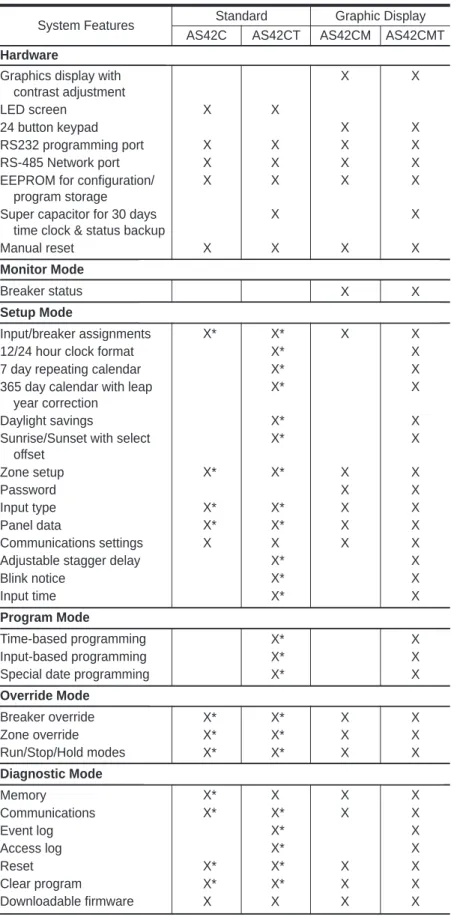
System Features
Hardware
Graphics display with contrast adjustment LED screen
24 button keypad RS232 programming port RS-485 Network port EEPROM for configuration/
program storage Super capacitor for 30 days
time clock & status backup Manual reset
Monitor Mode
Breaker status
Setup Mode
Input/breaker assignments 12/24 hour clock format 7 day repeating calendar 365 day calendar with leap
year correction Daylight savings
Sunrise/Sunset with select offset Zone setup Password Input type Panel data Communications settings Adjustable stagger delay Blink notice
Input time
Program Mode
Time-based programming Input-based programming Special date programming
Override Mode Breaker override Zone override Run/Stop/Hold modes Diagnostic Mode Memory Communications Event log Access log Reset
Standard Graphic Display AS42C AS42CT AS42CM AS42CMT
X X X X X X X X X X X X X X X X X X X X X X X X X X X* X* X X X* X X* X X* X X* X X* X X* X* X X X X X* X* X X X* X* X X X X X X X* X X* X X* X X* X X* X X* X X* X* X X X* X* X X X* X* X X X* X X X X* X* X X X* X X* X X* X* X X
SELECTION DATA
Description StandardStandard time of day Graphic Display
Graphic Display Time of day
Catalog Number AS42C AS42C-T AS42CM AS42CM-T
Control Modules
Graphical Display Control Module
The graphical display control module (AS42CM and AS42CM-T), shown in figure 4, displays system status and program information using an LCD screen (A). System configuration and programming are performed using the module selection keys (B). Screen contrast can be adjusted to the desired value using the module’s contrast control (C). The control module can be reset manually by depressing the reset button (D) with a paper clip or similar tool. This will restart operation without affecting system configura-tion. In addition to the network connection, a temporary link is available using the RS-232 (serial) communications port (E).
Entering the Program
You can program the graphical display control module in one of three ways:
1) Local desktop mode (see page 35):
Requires: Power supply—AS42CM-DPK
Procedure: Use the 24-button keypad on the control module to enter setup information.
2) Local desktop mode (see page 35):
Requires: Power supply—AS42CM-DPK Serial cable—AS42CM-SC
Software—PLK-101 or CMS 1000 installed on a personal computer or workstation.
Procedure: Use AS42CM-SC cable to connect a personal computer to the RS-232 communication port on the control module. You can then download configuration information from POWERLINK software to the control module.
3) Network mode:
Requires: Power supply—A control module plugged into an energized POWERLINK panelboard.
Software—POWERLINK PLK 101 or CMS 1000 installed on a remote personal computer or workstation.
Procedure: Set up the communications options in the control module (i.e., network address and baud rate). Connect the personal computer and the POWERLINK panelboard to the network. Then use POWERLINK software to down-load configuration information to the control module.
Events
Circuit breakers are turned on or off based on an event. A control module will accept up to 256 programmed events. Events can be on automatic control, such as time-of-day, or signalled by an input change (e.g., moving a light switch from on to off). Output signals are sent from the control module to the circuit breakers via the power interface module.
Overrides
An override changes the state of an output independent of the control module program. Three types of overrides may be initiated from the control module:
Figure 4–Graphical display control module A—LCD Screen
B—Selection Keys C—Contrast Control D—Reset button
E—RS-232 Communications Port
Note: If using the RS-232 port on the control module, serial
Override conditions may be selected as temporary, which will be in effect until the next event, or continuous, which remains in effect until released. Individual circuit breakers have the switching mode selector switch, which takes priority over overrides initiated from the control module.
Operating Modes
There are three modes of operation:
1. Run—System responds automatically to events. All system features and functions are working. Single-event, on-line programming is allowed. 2. Manual—All circuit breakers are turned on, and events are not
processed. All remote and network data is ignored.
3. Hold—Control signals are not processed, but events are logged. Outputs are updated when the mode of operation is returned to RUN. Overrides, diagnostics, and local programming are allowed.
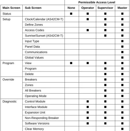
Access Codes
The control module uses a four-digit access code to control program security. There are three levels of security, each level requiring its own access code. If no key is pressed for five minutes, an access code will “time out,” and it must be re-entered.
Control Modules
Permissible Access Level Main Screen Sub Screen None Operator Supervisor Master
Status ■ ■ ■ ■
Setup Clock/Calendar (AS42CM-T) ■ ■ ■
Define Zones ■ ■ Access Codes ■ ■ ■ Sunrise/Sunset (AS42CM-T) ■ ■ Input Type ■ Panel Data ■ Communications ■ Global Values ■ Program View ■ ■ ■ ■ Program ■ ■ Delete ■ ■ Override Breakers ■ ■ Zones ■ ■ All Breakers ■ ■ Operating Mode ■ ■
Diagnostic Control Module ■ ■ ■
Interface Module ■ ■ ■
Expansion Unit ■ ■ ■
Non-Responding Breaker ■ ■ ■
Software Versions ■ ■ ■
Clear Memory ■
Control Modules
Names
For control modules programmed with a PC, an operational 12-character alphanumeric name tag can be assigned to individual circuit breakers or zones of circuit breakers within a panelboard. Name tags will not actually appear unless a name has been entered for that item, using a PC and PLK-101 or CMS-1000 software.
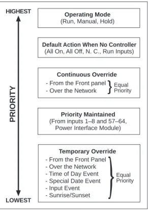
Priorities
In cases of conflicting commands, such as a time-based event telling a circuit breaker to turn on and an input event telling a circuit breaker to turn off, a priority system is used. Higher priority commands override lower priority commands. Refer to Table 7 to see how the POWERLINK AS system assigns priorities.
Screen Organization
The control module organizes screens under five headings: Status, Setup, Program, Override, and Diagnostic. These are listed across the top of the screen (A) on all five main screens (see figure 5).
1. Status screen—shows the position, pole number, and status of all circuit breakers, indicating if the circuit breaker is on, off, or overridden. The screen also displays present operating mode, and time of day and date, (time-of-day control module only). This is the default screen on power-up. 2. Setup screens—used to set up the system configuration,
communications, and global values. This must be completed before any programming functions can be performed.
3. Program screens—used to program the system for desired operation. 4. Override screens—used to override breaker position.
5. Diagnostic screens—used to evaluate system performance, and for troubleshooting.
Selection Keys
The selection keys (B) on either side of the LCD are used for entering the program choices. The keys operate only if there is an arrow next to them. Solid arrows indicate that the key will modify a choice on
that screen.
Hollow arrows indicate that the key will advance you to a new screen.
The keys will stay in a neutral position until actuated and can be moved to a minus (-) or plus (+) position.
Access Codes Screens
The control module displays the access code screen as necessary. If a screen with restricted access is requested by a user without access authorization, the module prompts the user to enter an access code before it displays the requested screen.
Global Values
Global values are set to affect all POWERLINK AS circuit breakers and all program items.
BLINK NOTICE—sets the number of minutes prior to a change that the
Operating Mode (Run, Manual, Hold)
Equal Priority - From the Front Panel
- Over the Network - Time of Day Event - Special Date Event - Input Event - Sunrise/Sunset
Temporary Override Default Action When No Controller
(All On, All Off, N. C., Run Inputs)
- From the Front panel - Over the Network
Equal Priority Continuous Override HIGHEST
LOWEST
PRIORITY
(From inputs 1–8 and 57–64,Priority Maintained Power Interface Module)Figure 5—Control Module Status Screen
AS
STATUS SETUP PROGRAM OVERRIDE DIAGNOSTIC
RESET
OPERATING MODE = RUN
BREAKER STATUS IS SHOWN BELOW = ON = OFF 11:00 AM 12/31/92 1 2 3 4 5 6 7 38 9 10 11 12 13 3436 16 17 31 32 33 21 22 37 24 25 26 27 28 29 30 41 42 40 20 BLINK = OVERRIDDEN 11:00 AM TU 05 / 02/ 95
B
A
11:00 AM TU 08 / 04/ 98 = ON = OFFC
D
E
Control Modules
SEQUENCE TIME—sets the time period between circuit breaker switching operations, when multiple circuit breakers are switch simultaneously with an event. Default value is 0.25 seconds, and sequence time may be user configured to either 0.25, 0.5, 1.0, 5.0, or 10.0 seconds.
DEFAULT ACTION IF NO CONTROL MODULE—defines the action by the system if control module is removed. Default action takes effect if the control module is removed from the system for more than one minute, or if no control module is present upon power-up.
The available user-defined default actions are:
ALL ON—All circuits forced on; no programs will execute. ALL OFF—All circuits forced off; no programs will execute.
NO CHANGE—All circuits remain in current state; no programs will execute. RUN INPUTS—Circuits will continue to respond to input-based programs; time-based programs, special date programs, and input timers will not execute. This is the system default.
Circuit Breaker Status
Circuit breaker status is indicated at the bottom of many screens. All circuit breakers available to the system are shown as numbers (refer to figure 3).
A white number in a black box indicates that the circuit breaker is in the off position.
A black number in a white box indicates that the circuit breaker is in the on position.
A white number in a blinking black box indicates that the circuit breaker is in the continuous off position.
A black number in a blinking white box indicates that the circuit breaker is in the continuous on position.
A white number in a dotted blinking black box indicates the breaker is commanded by a priority maintained input to turn off.
A dotted blinking black number in a dotted blinking white box indicates the breaker is commanded by a priority maintained input to turn on. Multi-pole circuit breakers are indicated by connected boxes:
A two-pole circuit breaker has two boxes with one number. A three-pole circuit breaker has three boxes with one number. Numbers represent the pole containing the internal 24Vdc motor and the 6-pin plug-on control bus connector.
Status Screen
The status screen is the default screen, which is displayed whenever the system is active. The control module returns to the status screen after five minutes of no activity.
The status screen displays (refer to figure 2 on previous page):
• Circuit breaker status (C), indicating if the circuit breaker is on (a black number in a white box, off (a white number in a black box), overridden on (a black number in a blinking white box), overridden off (a white number in
#
#
#
#
# ##
Control Modules
A—Selection Keys B—LED Display C—Reset Button
D—Display Mode Indicators E—RS-232 Communications Port F—Communications Activity Indicators G—Status Indicators
Figure 6–Standard control module + -+ – + – + – + – + – + – + – + – + – + – + – + – AS COMMUNICATIONS SETUP ADDRESS STATUS K BAUD CPU RX CLK TX SELECT MODIFY
C
D
F
E
A
B
G
Standard Control Module
The standard control module (AS42C and AS42C-T), shown in figure 6, displays status and communication parameters using indicators (D, F, G) and an LED display (B). System configuration is done using selec-tion keys (A). In addiselec-tion to the network connecselec-tion, a temporary link is available using the RS-232 (serial) communications port (E). The control module can be reset manually by depressing the reset button (C) with a paper clip or similar tool. This will restart operation without affecting system configuration.
Entering the Program
You can program the standard control module in one of two ways: 1) Local desktop mode (see page 35):
Requires: Power supply—AS42CM-DPK Serial cable—AS42CM-SC
Software—PLK-101 or CMS 1000 installed on a remote personal computer or workstation.
Procedure: Use AS42CM-SC cable to connect a personal computer to the RS-232 communication port on the control module. You can then download configuration information from POWERLINK software to the control module.
2) Network mode:
Requires: Power supply—A control module plugged into an energized POWERLINK panelboard.
Software—POWERLINK PLK 101 or CMS 1000 installed on a remote personal computer or workstation.
Procedure: Set up the communications options in the control module (i.e., network address and baud rate). Connect the personal computer and the POWERLINK panelboard to the network. Then use POWERLINK software to down-load configuration information to the control module. • The overridden legend (blinking white box) will appear only if one or
more of the circuit breakers is overridden.
• The operating mode (D) of the system (run, manual, or hold). • Internal time and date (E) (appears with optional time-of-day control
modules only). If time does not include AM or PM, then the internal clock is using a 24-hour display.
General Information
NQOD Panelboard Features:
• Industrially-proven rugged construction.
• Circuit breakers are multi-pole, multi-amp, HACR, HID, and SWD rated.
• Maximum voltage: 240 Vac.
• Maximum mains ampacity: 225 A main lug; 250 A main circuit breaker.
• Maximum branch ampacity:
— 30 A QO(B)-AS POWERLINK breaker. — 125 A QO plug-on standard breaker. — 150 A QO(B) bolt-on standard breaker. — (1) 225 A sub-feed breaker.
NEHB Panelboard Features:
• Industrially-proven rugged construction.
• Circuit breakers are multi-pole, multi-amp, HACR, HID, and SWD rated.
• Maximum voltage: 480Y/277 Vac.
• Maximum mains ampacity: 225 A main lug; 250 A main circuit breaker.
• Maximum branch ampacity:
— 30 A EHB-AS POWERLINK breaker. — 60 A EH plug-on standard breaker. — 100 A EHB bolt-on standard breaker. — (1) 225 A sub-feed breaker.
• UL listed, Class CTL panelboard meets para-graph 384-15 of the NEC.
• Distributed phase bussing. Branch circuit breakers may be mounted in any position.
Interiors:
• Will accept plug-on or bolt-on branch circuit breakers.
• Suitable for use as a service entrance (statement found on wiring diagram.
• Top or bottom feed.
• 65k AIR maximum standard branch circuit breakers (fully rated).
• 200k AIR maximum when supplied by remote I-LIMITER® circuit breaker (series rated).
• 100 A and 225 A are suitable for use as service entrance with back-fed QO(B) circuit breaker. • Field installable sub-feed lug kits for 100–225 A
interiors.
• Factory installed main lugs on all interiors. • 225 A main lug interiors are convertible to main
circuit breaker by adding a main circuit breaker and adapter kit.
• Available with silver-plated copper or tin-plated aluminum bus (aluminum is standard). Tin-plated copper bus is an available option. Branch connector fingers are all tin-plated copper; silver-plated branch connector fingers are optional.
Main Circuit Breakers:
• 100 A main circuit breaker interiors consist of factory installed back-fed QO(B) main circuit breaker.
• 225 A main circuit breaker interiors use: — Standard main lug interiors.
— Main circuit breaker adapter kit.
— Appropriate Q2L, Q2L-H, Q2LH, KAL, KHL, KDL, KGL, KCL, or KIL circuit breaker.
Enclosures (NEMA Type 1) Boxes:
• Galvanized steel with removable endwalls. One endwall is provided with knockouts and the other endwall is blank.
• Size: 20 in. (508 mm) wide x 5.75 in. (146 mm) deep.
• Box and interior mounting instructions are found in the information manual shipped with the interior.
• Interiors mount directly to studs in the boxes. No interior mounting brackets are required.
Fronts:
• Finished with gray baked enamel electrodepos-ited over cleaned phospha-tized steel (ANSI 49). • Flush or surface mounted.
• Door with flush lock. Uses NSR-251 key. • Directory card is located on the inside of the door. • MONO-FLAT® fronts on 100–225 A interiors
mount to the interior trim with trim screws. Both trim screws and door hinges are concealed. Fronts are not removable with the door closed and locked.
• Fronts 56 in. (1422 mm) high or more have sliding vault locks and 3-point latching.
Enclosure Options for NQOD and NEHB Panelboards
Types Environment Provides Protection Against
NEMA Type 1 Indoor Contact with enclosed equipment NEMA Type 3R Outdoor Rain, sleet, ice
NEMA Type 5 Indoor Dust, dirt, liquids NEMA Type 12 Indoor Dust, dirt, liquids
Series Ratings
System Voltage (Maximum) UL Series Connected Rating (AIR) MainType AmperesMax. Type Amperes Poles Branch QO-AS, QOB-AS QO-AS, QOB-AS QO-AS, QOB-AS QO-AS, QOB-AS QO-AS, QOB-AS QO-AS, QOB-AS QOB-VH Q2-H FC KC FI KI 150 225 100 250 100 250 1 2 3 1 2 3 1 2 3 1 2 3 1 2 3 1 2 3 22,000 100,000 200,000 240Vac
UL Certified Series Connected Ratings
This page contains UL tested and certified series combination ratings for panelboards. These ratings apply to either an integral main located in the same enclosure or a remote main located in a separate enclosure.
System Voltage (Maximum) UL Series Connected Rating (AIR) Main
Type AmperesMax. Type Amperes Poles Branch EHB-AS EHB-AS EHB-AS EHB-AS EHB-AS FC KC FI KI Class J Fuse 100 250 100 250 200 1 2 3 1 2 3 1 2 3 1 2 3 1 2 3 65,000 100,000 240Y/ 277Vac 480Y/ 277Vac 15–30 15–20 15–20 15–30 15–20 15–20 15–30 15–20 15–20 15–30 15–20 15–20 15–30 15–20 15–20 15–30 15–30 15–30 15–30 15–30 15–30 15–30 15–30 15–30 15–30 15–30 15–30 15–30 15–30 15–30 15–30 15–30 15–30 POWERLINK AS panelboard with 1-, 2-, and 3-pole series-rated circuit breakers with high interrupting 250 amp main circuit breaker.
Table 8 NQOD Series Ratings
Interior Trim 3.00 76 10.44266 Main Lugs Solid Neutral A 0.375 Dia. 10 20.00 508
Typical Box with Interior
Flush Lock
Typical Front
H
Concealed Door Hinges
Typical Mounting of QO, QOB Circuit Breakers Typical Box Side View 5.75 146 0.25 Mounting 6 Hole Emboss 2.50 (20" Wide Box) 64 Flush Mounting W + 1.50 38 Surface Mounting W + 0.12 3 Flush Mounting H + 1.50 38 Surface Mounting H + 0.12 3 B C E D
Typical Side View with Mounting Provisions
H 6.50 165 1.00 25 0.50 13 Typical Endwall H minus 1.20 30 20.00 508 4.78 121 2.50 64 2.50 64
Typical Front View
Interior Mounting Studs
B QO, QOB Circuit BreakersTypical Mounting of
Indoor—NEMA Type 1 Outdoor—NEMA Type 3R ▲ ■ ■ Maximum Main Lug Ampere Rating 100 23.00 23.00 26.00 32.00 584 584 660 813 17.90 17.90 20.90 26.90 455 455 531 683 18.00 18.00 21.00 27.00 457 457 533 686 H A B IN mm IN mm IN mm Required Panel Size 20 24 30 30 Interior
Box Height Deadfront Length
18.88 18.88 21.88 27.88 480 480 556 708 C mm IN 6.89 6.89 6.89 11.43 175 175 175 290 D mm IN
MLO Wire Bending
5.46 5.46 5.46 10.00 139 139 139 254 E mm IN S/N Wire Bending Maximum Number of Circuits PowerLink 14 18 24 24
Mounting Studs Mounting Holes
NQOD Main Lug Panelboards (225 Ampere Maximum Main Lugs)
Dimensions: INCHES mm
Note: Refer to page 34 for keyhole and endwall detail.
Interior Trim 3.00 76 10.44 266 Solid Neutral A 20.00 508
Typical Box with Interior
H
Flush Lock
Typical Front
Concealed Door Hinges
Typical Mounting of QO, QOB Breakers 17.46 443 Typical Box Side View 5.75 146 0.25 Mounting 6 Hole Emboss Flush Mounting W + 1.50 38 Flush Mounting W + 1.50 38 Surface Mounting W + 0.12 3 Surface Mounting W + 0.12 3 2.50 (20" Wide Box) 64 C B D E 0.375 Dia. 10
Typical Side View with Mounting Provisions
H 6.50 165 1.00 25 0.50 13 H minus 1.20 30 20.00 508 4.78 121 2.50 64 2.50 64
Typical Front View
Interior Mounting Studs
B
Typical Endwall Typical Mounting of QO, QOB Circuit Breakers
Indoor—NEMA Type 1 Outdoor—NEMA Type 3R Maximum Main Circuit Breaker Ampere Rating 100 35.00 35.00 38.00 35.00 889 889 965 889 29.90 29.90 32.90 29.90 759 759 836 759 30.00 30.00 33.00 30.00 762 762 838 762 20 24 30 20 30.88 30.88 33.88 30.88 784 784 860 784 11.82 300
D (from Center Line of CB)
14 18 24 14
FAL , FHL 10.06 256 8.08 205
E (from Line Lugs of CB) Top Feed 8.08 205 Bottom Feed H A B IN mm IN mm IN mm Required Panel Size Interior
Box Height Deadfront Length
C mm IN Maximum Number of Circuits PowerLink mm mm mm mm IN IN IN IN
Top Feed Bottom Feed Mounting Studs Mounting Holes
★ ★
▲ ■ ■ ▲
NQOD Main Circuit Breaker Panelboards (100 Ampere Maximum Main Circuit Breaker)
Dimensions: INCHESmm Note: Refer to page ___ for keyhole and endwall detail.
Interior Trim 3.00 76 10.44 266 Solid Neutral A 20.00 508
Typical Box with Interior
H D E Flush Lock Typical Front Concealed Door Hinges Typical Mounting of QO, QOB Circuit Breakers 22.00 559 Typical Box Side View 5.75 146 0.25 Mounting 6 Hole Emboss 2.50 (20" Wide Box) 64 Flush Mounting W + 1.50 38 Surface Mounting W + 0.12 3 Flush Mounting H + 1.50 38 Surface Mounting H + 0.12 3 B C 0.375 Dia. 10 Indoor—NEMA Type 1 Outdoor—NEMA Type 3R
Typical Side View with Mounting Provisions
H 6.50 165 1.00 25 0.50 13 H minus 1.20 30 20.00 508 4.78 121 2.50 64 2.50 64
Typical Front View
Interior Mounting Studs
B
Typical Endwall Typical Mounting of QO, QOB Circuit Breakers
225 Q2L 44.00 50.00 56.00 1118 1270 1422 39.00 45.00 51.00 991 1143 1295 39.88 45.88 51.88 1013 1165 1318 30 42 54 39.90 44.75 50.75 1013 1137 1289 16.89 432 24 36 42 Q2L-H, Q2LH 15.88 393 13.66 347 12.79 325
D (from Center Line of CB) E (from Line Lugs of CB) Top Feed Bottom Feed
H A B IN mm IN mm IN mm Required Panel Size Interior
Box Height Deadfront Length
C mm IN Maximum Number of Circuits PowerLink mm mm mm mm IN IN IN IN
Top Feed Bottom Feed Maximum Main
Circuit Breaker Ampere Rating
Mounting Studs Mounting Holes
Dimensions: INCHESmm Note: Refer to page 34 for keyhole and endwall detail.
NQOD Main Circuit Breaker Panelboards (250 Ampere Maximum Main Circuit Breaker)
5.75 146 8.50 216 2.50 64 A B H 2.00 51 2.50 64 2.50 64 4.78 121 4.78 121 10.44 265 20.00 508 Interior Trim
TYPICAL BOX WITH INTERIOR
TYPICAL BOX SIDE VIEW Directory Card Holder Flush Lock TYPICAL FRONT Surface Mounting H + .13 3 Flush Mounting H + 1.50 38 3.06 78 7.69 195 1.38 35 3.06 78 15 Concentric KO.(12, 34) 1 1( 14, 12, 12, Concentric KO. 1 2, 2 3) TYP. 1 1( 14, 12, 12, Concentric KO. 1 2, 2 3, 312) 6 Concentric KO.(12, 34) TYPICAL ENDWALL 21.50 546 Flush Mounting 20.13 511 Surface Mounting Concealed Trim Clamps Concealed Door Hinges
TYPICAL MOUNTING OF EH OR EHB BREAKERS
TYPICAL WIRING DIAGRAM
S/N Maximum Main Lug Ampere Rating 12 24 24 36 42 125 225 29.00 35.00 35.00 41.00 47.00 737 889 889 1041 1194 24.00 30.00 30.00 36.00 42.00 610 762 762 914 1067 25.00 31.00 31.00 37.00 43.00 635 787 787 940 1092 18 30 30 42 54 H A IN mm IN mm IN mm Required Panel Size Interior Box Height B Maximum Number of Circuits PowerLink
Mounting Studs Mounting Holes
Dimensions: INCHES mm
Note: Refer to page 34 for keyhole and endwall detail.
NEHB Main Lug Panelboards (225 Ampere Maximum Main Lugs)
20 in. (508 mm) Wide Enclosures
3.06 78 7.69 195 1.38 35 3.06 78 15 Concentric KO.(12, 34) 1 1( 14, 12, 12, Concentric KO. 1 2, 2 3) TYP. 1 1( 14, 12, 12, Concentric KO. 1 2, 2 3, 312) 6 Concentric KO. (12, 34) TYPICAL ENDWALL 21.50 546 Flush Mounting 20.13 511 Surface Mounting Concealed Trim Clamps Concealed Door Hinges TYPICAL MOUNTING OF EH OR EHB BREAKERSTYPICAL WIRING DIAGRAM
S/N 5.75 146 8.50 216 2.50 64 A B H 2.00 51 2.50 64 2.50 64 4.78 121 4.78121 10.44 265 20.00 508 Interior Trim TYPICAL BOX WITH INTERIOR TYPICAL BOX SIDE VIEW Directory Card Holder Flush Lock TYPICAL FRONT H minus 7.22 183 Flush = H plus 1.50 38 12.68 322 Surface = H plus .13 3 12 24 24 36 42 125 250 38.00 44.00 47.00 53.00 59.00 965 1118 1194 1346 1449 33.00 39.00 42.00 48.00 54.00 838 991 1067 1219 1372 34.00 40.00 43.00 49.00 55.00 864 1016 1092 1245 1397 18 30 30 42 54 H A IN mm IN mm IN mm Required Panel Size Interior Box Height B Maximum Number of Circuits PowerLink Maximum Main Circuit Breaker Ampere Rating
Mounting Studs Mounting Holes
Dimensions: INCHES mm
Note: Refer to page 34 for keyhole and endwall detail.
20 in. (508 mm) Wide Enclosures
7.69 195 3.06 78 15 (1⁄2, 3⁄4) Concentric KO 6 (1⁄2, 3⁄4) Concentric KO 1 (11⁄4, 11⁄2, 2, 21⁄2, 3) Concentric KO 1 (11⁄4, 11⁄2, 2, 21⁄2, 3, 31⁄2) Concentric KO 3.06 78 1.38Typ. 3520" Wide Endwall with Knockouts (Other Endwall is Blank)
1 (3⁄4, 11⁄2, 2, 21⁄2) Concentric KO 24 (1⁄2, 3⁄4) Concentric KO 9⁄32 KO 1.38 35
14" Wide Endwall with Knockouts (Other Endwall is Blank)
3.00 76 1.75 44 1.12 28 0.31 8 0.50 13 Keyhole Detail (2 Holes Typical)
NQOD and NEHB Keyhole and Endwall Detail
Dimensions: INCHES mm
Desktop Power Supply
POWERLINK AS desktop programming power supplies allow POWERLINK AS control modules to be programmed without being installed in the panel. The desktop power supply operation is very similar to a standard calculator type power supply. Simply plug the power supply into a standard 120V, 60 Hz wall outlet, and insert the 9-pin connector into the back of the module. When powering up, the control module will follow its initialization sequence, and then display the status screen. Since the control module is not installed in a panel, it will assume that 42 1-pole POWERLINK AS circuit breakers are present. This permits all 42 circuit breaker locations to be programmed. Multi-pole breakers can be programmed by selecting the pole number corresponding to the motor location (see figure 7 below).
Desktop programming of the control module can be done by either of the methods listed below:
Using application software:
• Connect a PC directly to the RS-232 port on the control module via the AS42CM-SC cable.
• Download programs from either PLK 101 or CMS 1000 software.
From control module:
• Program the control module by manually selecting the desired functions using the module’s 24-button keypad. (For more information, see the control module section on page 20.
After the control module is programmed, it is ready for installation in the panelboard.
Desktop power supply connected to control module
Control module connected to PC via AS42CM-SC cable
AS42CM-SC Cable
SELECTION DATA
Description Desktop Power Supply RS-232 Download Cable
Catalog Number AS42CM-DPK
AS42CM-SC
Input Expansion Cabinet
The input expansion cabinet provides 42 additional outputs and 48 additional inputs over the 16 inputs available within the POWERLINK AS system. It’s a simple and low cost way to multiply your system’s capabilities.
The POWERLINK system input expansion cabinet allows you to multiply the benefits of the POWERLINK AS remote power switching system without complicated installation or operation procedures. It provides as many as 48 additional inputs over the 16 inputs available within the POWERLINK AS system.
The POWERLINK system input expansion cabinet is ideal for new or retrofit lighting applications. Its efficient design significantly reduces installation and maintenance time, while its low voltage switching (24V) provides safe and easy operation.
Installation costs are reduced because the system accepts low voltage Class 2 wiring, which typically requires no conduit. Inputs used with Class 2 wiring include low voltage switches, motion detectors, and photo cells, which can be 2-wire maintained, 2-wire momentary, or 3-wire momentary. In most lighting applications, low voltage switches operating at 24Vdc will be used. These switches can be conveniently programmed to provide a variety of tasks, including simple on/off switching, overriding a programmed event, or acting as a simple timer.
The POWERLINK system input expansion cabinet is easily reprogrammed to meet a facility’s changing requirements without rewiring. Each of the 48 inputs can be individually activated by input control devices. And with the system’s superior design flexibility, there can be as few as one or as many as 48 inputs per zone.
If your objective is to reduce energy costs and take advantage of remote low voltage switching, the POWERLINK system input expansion cabinet is your best solution.
COMPONENTS
AS48EXP
• Input/output expansion cabinet
• Accepts (2) AS24IN and (1) AS42OUT modules
• Sources control power for dry contact type inputs and outputs
AS24IN
• Provides for 24 additional 2-wire maintained or 3-wire momentary contact inputs
AS48OUT
• Provides for 42 additional outputs • 115 mA maximum current per output
• Total current load not to exceed 1.65 A on all outputs
SELECTION DATA
Description
Input Expansion Chassis — accepts up to two AS24IN and one AS42OUT Modules
Input Module — contains provisions for 24 inputs Output Module — contains provisions for 42 outputs Expander Enclosure
Surface Cover for AS48EXP Flush Cover for AS48EXP
Catalog Number AS48EXP* AS24IN** AS42OUT MH26-BEPL MHC26PL-S MHC26PL-F * Input Expansion Cabinet includes power supply, interior, and serial communication board for connection to the power interface module.
** AS24IN accepts either 2-wire maintained, 2-wire momentary, or 3-wire momentary input signals.