5.0L SEFI EEC IV TESTING
1987 Lincoln Mark VII
1987 Computerized Engine Controls
FORD MOTOR CO. EEC IV DIAGNOSIS & TESTING 5.0L SEFI
DIAGNOSIS & TESTING
DIAGNOSTIC PROCEDURE
This diagnostic procedure is used to test and service the EEC-IV system. It is divided into 2 test formats: QUICK TEST, a functional system test, and CIRCUIT TESTS, a number of specific circuit and component tests. To test and service EEC-IV system, perform the QUICK TEST first.
If vehicle passes KEY ON/ENGINE OFF (KOEO), KEY ON/ENGINE RUNNING (KOER), and CONTINUOUS SELF-TESTS of QUICK TEST without running any CIRCUIT TESTS, the EEC-IV system is okay. Problem exists somewhere else besides the EEC-IV system. If QUICK TEST fails, perform only those tests that are specified by the failed step.
TEST CONNECTOR LOCATIONS
All Mustang models have SELF-TEST connector on left rear corner of engine compartment.
On Continental and Mark VII models, the SELF-TEST connector is on the right side of the engine compartment, near firewall. The Crown Victoria, Grand Marquis and Town Car, have the SELF-TEST connector on left fender apron, above wheelwell (near fuel pump relay).
PREPARATION FOR TESTING
Correct test results for system are dependent on the correct operation of several related EEC components and systems. All non-EEC problems should be corrected before attempting to diagnose the non-EEC system.
Before hooking up any equipment to diagnose the EEC system, make the following checks:
* Verify condition of air cleaner and air ducting.
* Check all vacuum hoses for leaks, restrictions, and proper routing.
* Check the EEC-IV system wiring harness electrical connections for corrosion, bent or broken pins, loose wires or terminals, and proper routing.
* Check the ECA, sensors and actuators for physical damage. * Perform all necessary safety precautions to prevent personal injury or vehicle damage.
* Set parking brake and place shift lever in "P" for automatic transmissions, and Neutral for manual transmissions. DO NOT move shift lever during testing unless specifically directed to do so.
* Turn off all lights and accessories, and make sure that vehicle doors are closed when making voltage or resistance readings.
* Start engine and idle until upper radiator hose is hot and pressurized and throttle is off fast idle. Check for leaks around exhaust manifold, exhaust gas oxygen sensor, and vacuum hose connections.
* Turn ignition key off. Service items as required, then go to EQUIPMENT HOOK-UP.
NOTE: If engine will not start, starts but stalls, idles rough or runs rough, go through KEY ON/ENGINE OFF SELF-TEST (KOEO). If any of the above conditions are still present after a code 11 in the KOEO SELF-TEST, go to CIRCUIT TEST A for a no start condition. If engine stalls or runs rough, go to DIAGNOSIS BY SYMPTOM TEST.
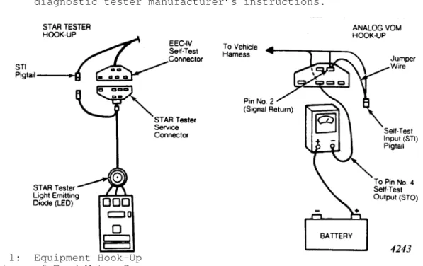
EQUIPMENT HOOK-UP
Analog Volt/Ohm Meter (VOM)
1) Turn ignition key off. Connect jumper wire from Self-Test Input (STI) pigtail to pin No. 2 (Signal Return) on SELF-TEST
connector. Set VOM at 0-15V DC range and connect positive lead of VOM to positive battery terminal.
2) Connect negative VOM lead to pin No. 4 (STO) on SELF-TEST connector. See Fig. 1. Connect timing light, then go to KEY ON/ENGINE OFF (KOEO) SELF-TEST.
STAR Tester
Turn ignition key off. Connect color coded adapter cable leads to diagnostic tester. Connect adapter cable’s 2 service
connectors to vehicle’s SELF-TEST connectors. Connect timing light, then go to KEY ON/ENGINE OFF (KOEO) SELF-TEST.
NOTE: Diagnostic tester hook-up instructions apply to STAR tester only. If other than STAR tester is being used, follow
diagnostic tester manufacturer’s instructions.
Fig. 1: Equipment Hook-Up Courtesy of Ford Motor Co.
TEST EQUIPMENT
The following equipment is recommended to diagnose and test EEC-IV system. Some equipment is REQUIRED to perform tests. DO NOT attempt to test this system without proper equipment. Damage to vehicle components will result if improper equipment is used. * The Self-Test Automatic Read-Out (STAR) Diagnostic Tester (Rotunda 007 00004) is recommended but not required. It is specially built for the EEC-IV system and is used to display, as numerals, the 2-digit service codes that are programmed into the control module.
* Analog Volt/Ohmmeter (VOM) with 0-20V DC range. This can be used as an alternate to diagnostic tester.
* Digital Volt/Ohmmeter (DVOM) with minimum 10-megaohm input impedance.
* Breakout Box (Rotunda 014-00322). This is a jumper wire assembly which connects between the vehicle harness and the ECA. The breakout box is REQUIRED to perform certain tests on the system. Ford Motor Co. specifically states that using the probe from a DVOM will cause PERMANENT DAMAGE to the ECA pin connector. "Test Pin(s) No." as called out in CIRCUIT TESTS refers to test pin number(s) on breakout box. Once the breakout box has been installed during a test sequence, it may be left connected for the remainder of the test.
* Vacuum gauge with 0-30 in. Hg range and resolution (unit on scale) of 1 in. Hg.
* Tachometer with 0-6000 RPM range, accuracy F 40 RPM, and a resolution of 20 RPM.
* Vacuum pump with 0-30 in. Hg range. * Timing light.
* Spark tester. A modified spark plug with side electrode removed and alligator clip attached may be used.
* Fuel Injection Pressure Gauge (Part No. T80L-9974-A). * Non-powered, 12-volt test lamp.
* Jumper wire, about 15" long.
* MAP/BP Tester. Unit plugs into MAP/BP sensor circuit and DVOM to check input and output voltages to verify correct sensor operation.
NOTE: STAR diagnostic tester is available from Hikok Electrical Instrument Co., 10514 Dupont Ave., Cleveland, OH 44106.
READING SELF-TEST CODES
Service codes are transmitted to Pin No. 4 (Self-Test Output) of SELF-TEST connector in the form of timed pulses. All service codes are 2 digit numbers which are generated one digit at a time. Codes are shown as voltage pulses (needle sweeps) on an analog volt/ohmmeter (VOM).
If a VOM is being used, careful attention to the length of the pauses is necessary in order to read the codes correctly. There will be a 2 second pause between each DIGIT in a code. There will be a 4 second pause between each CODE. The continuous memory codes are separated from the functional test service codes by a 6 second delay, a single 1/2 second sweep, and another 6 second delay.
If a diagnostic tester is used, it will count the pulses and display them as a digital code. The STAR tester will add a zero (0) to single digit (Separator and Dynamic Response) codes.
Separator Pulse
A single 1/2 second separator pulse is issued 6-9 seconds after last functional KEY ON/ENGINE OFF (KOEO) SELF-TEST code. Then 6-9 seconds after the single 1/2 second separator pulse, the continuous memory codes will be displayed.
Continuous Memory Codes
These codes are issued as a result of information stored during CONTINUOUS MONITOR (WIGGLE) TEST. These codes are displayed only during KEY ON/ENGINE OFF (KOEO) SELF-TEST and after separator code. These codes should be used to diagnose ONLY when (KOEO) and KEY ON/ENGINE RUNNING (KOER) SELF-TESTS result in code 11 and all QUICK TEST steps have been successfully completed.
QUICK TESTS
The QUICK TEST diagnostic procedure is a functional test of the EEC-IV system. It consists of 4 basic test steps. These basic steps must be carefully followed in sequence, otherwise misdiagnosis, or replacement of non-faulty components may result.
Perform QUICK TEST as follows: perform PREPARATION and EQUIPMENT HOOK-UP steps, KEY ON/ENGINE OFF (KOEO) SELF-TEST, TIMING CHECK, KEY ON/ENGINE RUNNING (KOER) TEST, and CONTINUOUS SELF-TEST. After all tests, servicing, or repairs have been completed, repeat QUICK TEST to ensure EEC-IV system works properly.
* The KEY ON/ENGINE OFF (KOEO) SELF-TEST is a static check of the EEC-IV system inputs and outputs. The TIMING CHECK
verifies the systems ability to compute and maintain a fixed spark timing during SELF-TEST.
* The KEY ON/ENGINE RUNNING (KOER) SELF-TEST is a dynamic system check with the engine under actual operating conditions and at normal operating temperature. The
CONTINUOUS SELF-TEST checks the sensor inputs for opens and shorts while the vehicle is in operation.
* The KEY ON/ENGINE OFF and KEY ON/ENGINE RUNNING SELF-TESTS are intended to detect faults present at the time of testing, not intermittent faults. Intermittent faults are detected by CONTINUOUS SELF-TEST.
KEY ON/ENGINE OFF (KOEO) SELF-TEST
NOTE: Continuous memory codes recorded in this step will be used for diagnosis in CONTINUOUS SELF-TEST.
Code Output
Correct test results for system are dependent on the correct operation of several related non-EEC components and systems. It may be necessary to correct faults in these areas before EEC-IV will pass QUICK TEST.
Verify that vehicle has been properly prepared. See
PREPARATION and EQUIPMENT HOOK-UP. Turn ignition on to start SELF-TEST. DO NOT depress throttle during test. Observe and record all service codes.
1) If engine does not start, go to CIRCUIT TEST A, step 1). If KEY ON/ENGINE OFF (KOEO) code and continuous memory indicate a pass (code 11), go to TIMING CHECK.
2) If any KOEO code is displayed with continuous memory code 11, KOEO SELF-TEST indicates a fault. Record codes and go to TEST RESULTS & ACTION TO TAKE in this test.
3) If any (KOEO) or any continuous memory code is displayed, (KOEO) SELF-TEST and continuous memory indicate a fault. Record codes,
but DO NOT repair continuous memory codes at this time. All (KOEO) and KEY ON/ENGINE RUNNING (KOER) SELF-TEST codes MUST be repaired first. Go to TEST RESULTS & ACTION TO TAKE in this test.
4) If (KOEO) code 11 displayed with ANY continuous memory code (except 15), continuous memory indicates a fault. Record codes, but DO NOT repair continuous memory codes at this time. (KOEO) and (KOER) SELF-TEST codes MUST be repaired first. Go to TIMING CHECK. If engine idles rough, go to DIAGNOSIS BY SYMPTOM TEST.
5) If (KOEO) code 11 is displayed and continuous memory code is 15, go to CIRCUIT TEST PP, step 9). If no codes are displayed, repeat SELF-TEST to verify that no service codes are present. If codes are not displayed, go to CIRCUIT TEST PP, step 1).
Test Results & Action To Take
1) Perform the test indicated in the KEY ON/ENGINE OFF (KOEO) SELF-TEST table for that specific engine. Start with the first code displayed. If the tests refer you to other checks, perform them as instructed.
2) When more than one code is displayed, repair problems in the order that codes are displayed. Whenever a repair is made, repeat QUICK TEST. If no codes are displayed, repeat SELF-TEST to verify that no service codes are present, and then go to CIRCUIT TEST PP, step 1). NOTE: See CIRCUIT TESTS at back of article.
CODE/TEST MENU (KOEO)
KEY ON/ENGINE OFF (KOEO) CIRCUIT TEST MENU
Code No. Go To: Circuit Test No. (Step No.) 15 ... PP (11) 19 ... PP (14) 21 ... G (1) 22 ... H (1) 23 ... J (1) 24 ... E (1) 31 ... M (1) 32 ... M (13) 34 ... M (12) 35 ... M (5) 51 ... G (4) 53 ... J (3) 54 ... E (5) 61 ... G (6) 63 ... J (6) 64 ... E (7) 67 ... O (1) 81 ... BB (8) 82 ... BB (8) 84 ... M (8) 85 ... CC (6) 87 ... Y (7)
TIMING CHECK
NOTE: If engine will not start, go to TEST A. If engine starts but stalls while testing, go to DIAGNOSIS BY SYMPTOM TEST.
1) Turn ignition key off, and then wait 10 seconds. Verify that SELF-TEST has been activated. Restart engine and check timing while in SELF-TEST mode. You are allowed 2 minutes to check timing from the time the last code is displayed.
2) Correct SELF-TEST timing equals base ignition timing (10
BTDC on all engines) plus 17-23
BTDC. If timing is not 27-33
BTDC,
go to CIRCUIT TEST OO. If timing is 27-33
BTDC, go to KEY ON/ENGINE RUNNING (KOER) SELF-TEST.
KEY ON/ENGINE RUNNING (KOER) SELF-TEST
NOTE: If engine will not start, go to TEST A. If engine starts but stalls while testing, go to DIAGNOSIS BY SYMPTOM TEST.
Code Output
1) Deactivate SELF-TEST (disconnect jumper wire). Start engine and run it at 2000 RPM for 2 minutes to warm up HEGO sensor. Turn engine off and wait 10 seconds
2) Start engine. Insert jumper to activate SELF-TEST. The engine ID code will be displayed.
3) If a Dynamic Response code occurs, briefly accelerate engine to wide open throttle (WOT). DO NOT depress throttle during test unless a Dynamic Response code occurs. The KEY ON/ENGINE RUNNING (KOER) SELF-TEST service codes will then be displayed. Observe and record all codes.
NOTE: On the 5.0L SEFI engine a service code 98 may appear instead of the engine ID code, indicating the need to obtain a code 11 for the KEY ON/ENGINE OFF (KOEO) SELF-TEST portion of the QUICK TEST.
Test Results & Action To Take
1) If no codes are displayed, repeat SELF-TEST to verify that no service codes are present, and then go to CIRCUIT TEST PP, step 1). If code 98 and any other code appears, go back and perform KEY
ON/ENGINE OFF (KOEO) SELF-TEST and obtain a code 11 for (KOEO) portion of QUICK TEST.
2) If Engine ID code is 2, 3 or 4 (20, 30 or 40 with STAR tester), and code 11 is displayed, KEY ON/ENGINE RUNNING (KOER) SELF-TEST portion is okay. If symptom was of an intermittent nature, go to CONTINUOUS SELF-TEST. If symptom is present, go to DIAGNOSIS BY
SYMPTOM TEST.
3) If Engine ID code is 2, 3 or 4 (20, 30 or 40 with STAR tester), and any code other than 11 appears, (KOER) SELF-TEST portion is at fault. Perform the test indicated in the (KOER) SELF-TEST table for that specific engine.
4) Start with the first code displayed. If the tests refer you to other checks, perform them as instructed. When more than one code is displayed, repair problems in the order that codes are displayed. Whenever a repair is made repeat QUICK TEST.
CODE/TEST MENU (KOER)
KEY ON/ENGINE RUNNING CIRCUIT TEST MENU
Code No. Go To: Circuit Test No. (Step No.) 12 ... DD (1) 13 ... DD (11) 16 ... DD (1) 21 ... G (1)
22 ... H (7) 23 ... J (1) 24 ... E (1) 31 ... M (1) 32 ... M (13) 33 ... M (14) 34 ... M (18) 35 ... M (5) 41 ... T (9) 42 ... S (8) 46 ... BB (1) 91 ... U (9) 92 ... T (15) 94 ... BB (1) 98 (1) ... ... 99 (2) ... ... (1) - If Code 98 is displayed, go back and perform KOEO SELF-TEST and obtain a Code 11 for KOEO part of QUICK-TEST. (2) - Idle Speed Control (ISC) has not "learned" yet, repeat QUICK TEST.
CONTINUOUS SELF-TEST
NOTE: CONTINUOUS SELF-TEST is subdivided into 4 steps: CONTINUOUS MEMORY CODES, CLEARING CONTINUOUS MEMORY CODES, CONTINUOUS MEMORY CODES TO BE TESTED, and CONTINUOUS MONITOR (WIGGLE TEST). Perform steps in sequence.
Continuous Memory Codes
1) To ensure proper diagnosis of continuous memory codes, PREPARATION, EQUIPMENT HOOK-UP, KEY ON/ENGINE OFF (KOEO) SELF-TEST, TIMING CHECK, and KEY ON/ENGINE RUNNING (KOER) SELF-TEST must be successfully completed. If both (KOEO) and (KOER) SELF-TEST display code 11 (Pass), go to CLEARING CONTINUOUS MEMORY CODES.
2) If not, return to PREPARATION step and make the necessary repairs indicated in (KOEO) and (KOER) SELF-TEST before going to CLEARING CONTINUOUS MEMORY CODES.
Clearing Continuous Memory Codes
Perform KEY ON/ENGINE OFF (KOEO) SELF-TEST. When the first service code appears, exit SELF-TEST by disconnecting diagnostic tester or by removing jumper wire from Self-Test Input (STI) pigtail. Exiting QUICK TEST in this manner will clear all codes stored in continuous memory.
Continuous Memory Codes To Be Tested
Check list of Continuous Memory codes that were recorded in KEY ON/ENGINE OFF (KOEO) and KEY ON/ENGINE RUNNING (KOER) SELF-TESTS. Disregard any codes that have already been repaired. To confirm
remaining codes, go to CONTINUOUS MONITOR (WIGGLE) TEST. Continuous Monitor (Wiggle) Test
The Self-Test Output (STO) will be activated each time a fault is detected. If the STO is activated long enough during the wiggle tests a service code will be stored. A fault is indicated by a deflection on VOM. The STAR tester LED will flash and/or sound an alert signal when fault is recreated. The CONTINUOUS MONITOR (WIGGLE) TEST is used to attempt to recreate an intermittent fault.
* KEY ON/ENGINE OFF (KOEO) Test: With SELF-TEST deactivated, turn ignition on to enter into wiggle test mode. Tap, move, and wiggle the suspected sensor and/or harness (in short sections). If a fault is detected, a service code will be stored in memory and will be indicated by VOM or diagnostic tester. Retrieve code and perform test indicated in
CONTINUOUS SELF-TEST table.
* KEY ON/ENGINE RUNNING (KOER) Test: Start engine. Activate SELF-TEST, wait 10 seconds, deactivate, and then reactivate SELF-TEST. DO NOT turn engine off. You are now in KOER wiggle test mode. Tap, move, and wiggle the suspected sensor and/or harness (in short sections). If a fault is detected, a
service code will be stored in memory and will be indicated by VOM or diagnostic tester. Retrieve code and perform test indicated in CONTINUOUS SELF-TEST table.
NOTE: An alternate method of entering CONTINUOUS MONITOR (WIGGLE) TEST with engine running is to start KEY ON/ENGINE RUNNING (KOER) SELF-TEST, exit, and re-enter KOER SELF-TEST without turning off engine. If alternate method is being used, perform the following steps.
1) Observe VOM while moving, wiggling, and tapping system harness (in short sections), connectors, and sensors. If an
intermittent condition is created, the monitor will indicate this by storing a service code. Carefully inspect harness and associated connectors of affected circuits.
2) If an intermittent condition is not created, carefully disconnect sensor from harness. Remove terminals from connector and visually inspect terminals at both ends for corrosion, bad crimps, improperly seated terminals, etc.
3) Reconnect harness after inspection. Disconnect ECA from harness as carefully as possible. Remove and inspect terminals associated with sensor being checked.
4) If an intermittent condition cannot be created, plug-in connector and erase the CONTINUOUS SELF-TEST service codes. To erase service codes, activate KEY ON/ENGINE OFF (KOEO) SELF-TEST.
5) Remove jumper wire from Self-Test Input (STI) terminal as soon as first code appears. Repeat SELF-TEST with jumper to verify that service codes have been erased. QUICK TEST is complete.
CODE/TEST MENU (CONTINUOUS)
CONTINUOUS SELF-TEST CIRCUIT TEST MENU TABLE
Code No. Go To: Circuit Test No. (Step No.) 14 ... TT (1) 15 ... PP (1) 18 ... NN (1) 22 ... H (15) 31 ... M (25) 32 ... M (23) 33 ... M (27) 34 ... M (29) 35 ... M (25) 51 ... G (10) 53 ... J (11) 54 ... E (10) 61 ... G (10)
63 ... J (15) 64 ... E (10)
QUICK TEST DIAGNOSTIC AIDS
Cylinder Balance TestThe cylinder balance test is an aid in servicing the 5.0L SEFI fuel system by energizing and de-energizing each injector separately. This test mode is entered after all codes have been displayed. Immediately following the KEY ON/ENGINE RUNNING (KOER) SELF-TEST, lightly depress throttle (a 2-3 degree throttle angle is required, NOT a wide open throttle). Service codes displayed during this test correspond to cylinder number.
CYLINDER BALANCE TEST SERVICE CODES TABLE
Service Cylinder/ Breakout Box Code Injector No. Test Pin No. 90 ... Pass ... Pass 10 ... 1 ... 58 20 ... 2 ... 59 30 ... 3 ... 12 40 ... 4 ... 13 50 ... 5 ... 14 60 ... 6 ... 15 70 ... 7 ... 42 80 ... 8 ... 52 77 ... Retest ... Retest
If code 90 is displayed during this test it indicates a pass. If code 77 is displayed, repeat cylinder balance test. If throttle is moved during this test, service code 77 will appear, indicating that test was not completed. Total test time is about 90 seconds.
Dynamic Response Check
The dynamic response check verifies movement of the TPS, and MAP sensor during the wide open throttle (WOT) part of the KEY
ON/ENGINE RUNNING (KOER) SELF-TEST. The signal to perform WOT is a single pulse (one) when using VOM or code 10 on STAR tester.
Output State Check
The Output State Check is used as an aid in servicing output actuators associated with the EEC-IV system. It allows you to energize and de-energize most of the system output actuators on and off on command.
This mode is entered after all codes have been received from KEY ON/ENGINE OFF (KOEO) and CONTINUOUS SELF-TEST. At this time, leave SELF-TEST activated and depress throttle. Each time throttle is
depressed, the output actuators will change state (go from on to off, or off to on).
DIAGNOSIS BY SYMPTOM TEST
The DIAGNOSIS BY SYMPTOM TEST is divided into specific engine sections. Each section will describe testing procedures and codes for that engine. Use appropriate DIAGNOSIS BY SYMPTOM TEST. The CIRCUIT TESTS are common to all engines, unless noted in test procedures.
5.0L SEFI
Use this test procedure ONLY when directed to do so by
results of QUICK TEST or steps in CIRCUIT TESTS. Follow test procedure carefully.
1) When engine stalls in operation, misfires, lacks power, idles roughly, or has erratic RPM, perform the following checks: * Check for, and repair, any bad ground or power connections. * Check ignition components (cap, rotor, wires, coil and plugs).
* Check basic engine components (valves, cam timing, compression, etc.).
* Perform SYSTEM CHECK, ISC Check, MAP Check, and EGR Check. Use CIRCUIT TEST QQ, steps 1), 2), and 3).
* Perform CYLINDER BALANCE TEST. See QUICK TEST DIAGNOSTIC AIDS in this article.
2) If fuel pump is always on (noise coming from rear of vehicle with key off), go to CIRCUIT TEST Y, step 12).
3) If shift indicator light is always on or off, go to CIRCUIT TEST FF, step 1).
4) If engine idle speed is low with A/C on, go to CIRCUIT TEST O, step 9).
5) If A/C does not cut-off during wide open throttle (WOT), go to CIRCUIT TEST GG, step 1).
6) If detonation (engine knock) occurs due to improper EGR valve function, check EGR and/or exhaust gas recirculation system. 7) If engine stalls during QUICK TEST due to faulty Idle Speed Control (ISC) operation, go to CIRCUIT TEST DD, step 4).
8) If gasoline fumes accumulate in engine compartment, go to CIRCUIT TEST CC, step 1).
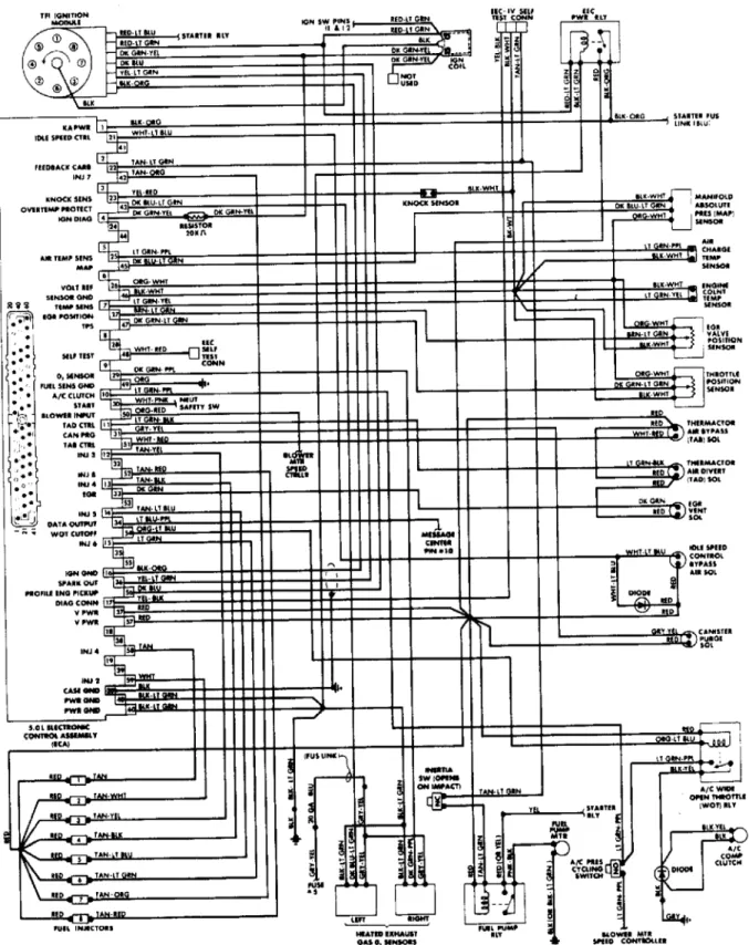
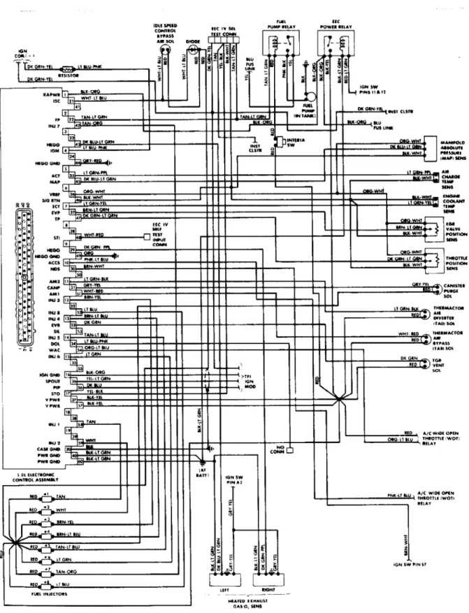
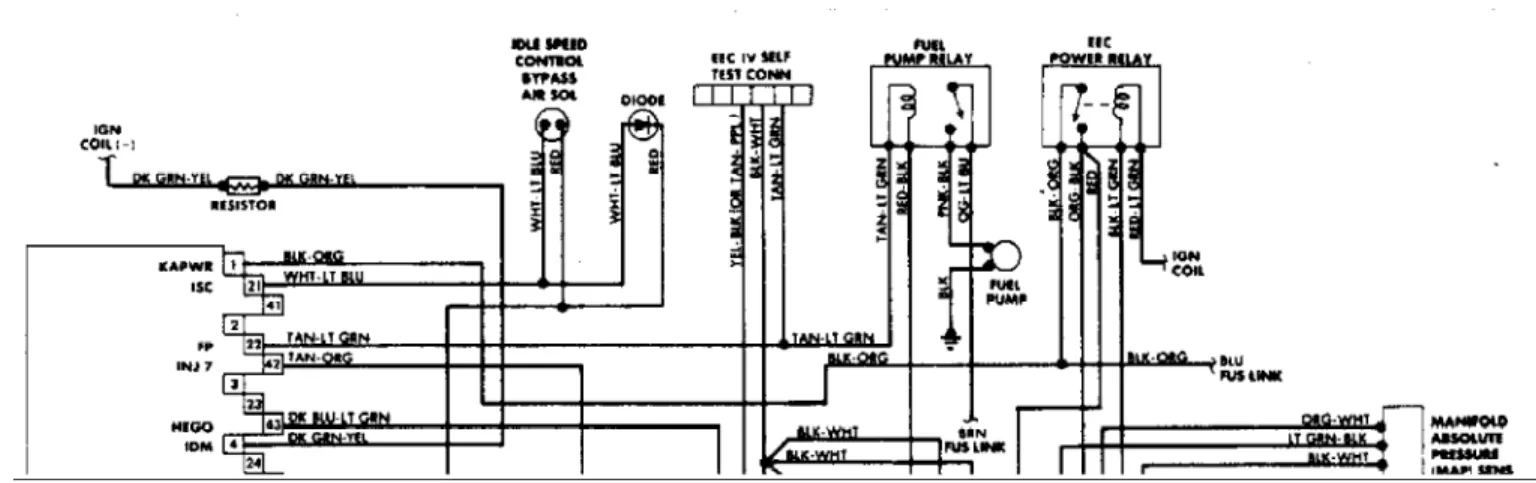
Fig. 6: 5.0L SEFI EEC-IV Wiring Diagram (Town Car)
HOW TO USE CIRCUIT TESTS
1) DO NOT perform any CIRCUIT TEST unless told to do so by QUICK TEST. Make sure all non-EEC related faults are corrected. Do not replace any part unless directed to do so. When more than one service code is received, start with the first code displayed.
NOTE: Procedures in the TESTING section of this article are not in absolute numerical order. Procedures not related to this engine have been removed to eliminate confusion.
2) Do not measure voltage or resistance at ECA or connect any test lamps to it, unless specified. All measurements are made by
probing REAR of connector. Isolate both ends of a circuit and turn key off whenever checking for shorts or continuity, unless specified. 3) Disconnect solenoids and switches from harness before measuring continuity, resistance, or applying 12 volts. Follow each test step in order until fault is found. After each repair, check all component connections and repeat CIRCUIT TEST(S).
4) An "open" is defined as any resistance reading higher than 5 ohms, unless specified in CIRCUIT TEST. A "short" is defined as any resistance reading less than 10,000 ohms to ground, unless specified in CIRCUIT TEST.
5) On FUEL CONTROL CIRCUIT TESTS S, T, U, V, W and X, to prevent replacement of good components, be aware that the following non-EEC related areas may also be at fault. These areas include ignition coil, distributor cap and rotor, spark plug wires, fouled spark plugs, CNAP problems, EGR valve and gasket, air filter, poor power and ground circuits, fuel pressure, intake and exhaust manifold leaks, engine not at normal operating temperature, and problems with PCV valves or fuel contaminated engine oil.
NOTE: Fuel contaminated engine oil may affect some service codes. If this is suspected, remove PCV valve from valve cover and repeat QUICK TEST. If problem is corrected, change engine oil and filter.
6) On FUEL CONTROL CIRCUIT TESTS S, T, U, V, W and X, vacuum leaks in non-EEC related areas may also cause code 41 or 91 to be displayed. Check for unmetered air between airflow meter and throttle body, leaking vacuum motors, engine seals, EGR system, PCV system, canister purge (CANP) problems, or contaminated HEGO sensor. Code 42 or 92 may be caused by fuel contaminated engine oil, ignition misfire, EGR system, or CANP problems.
NOTE: In the following diagnostic charts, circuits and illustrations are supplied courtesy of Ford Motor Co.
TEST A - NO START
To prevent replacement of good components, be aware that the following non-EEC related areas may be at fault: fuel quantity and quality, ignition system damage, cracks, moisture, etc., engine mechanical conditions such as bad valves, timing belt, etc. Also included are starter and battery circuit problems.
1) Try to start engine. If engine does not crank, check vehicle starting and charging systems. If engine cranks, but does not start or else stalls after starting, go to next step.
2) Turn key off and wait 10 seconds. Set DVOM on 20-volt scale and disconnect Throttle Position Sensor (TPS). Turn key on, leaving engine off. Measure voltage at TPS harness connector between voltage reference (VREF) and signal return. If reading is less than 4. 0 volts or more than 6.0 volts, go to CIRCUIT TEST C, step 1). If reading is between 4.0 and 6.0 volts, reconnect TPS and go to next
step.
3) Disconnect any spark plug wire and connect spark tester between plug wire and engine ground. Crank engine and check for spark. If spark exists, connect spark plug wire and go to step 13). If there is no spark, connect spark plug wire and go to next step.
4) Remove high tension coil wire from distributor and install spark tester. Check for spark while cranking engine. If spark exists, connect coil wire and service or repair TFI ignition system. If there is no spark, connect coil wire and go to next step.
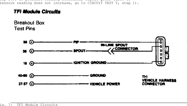
5) Turn key off and wait 10 seconds. Install breakout box, leaving ECA disconnected. Set DVOM on 200-ohm scale and disconnect TFI. Measure resistance between test pin No. 16 and TFI harness connector ignition ground. If reading is more than 5 ohms, repair harness and repeat QUICK TEST. If reading is less than 5 ohms, go to next step.
6) With breakout box installed and box timing switch on "DISTRIBUTOR" position, connect TFI and ECA. Try to start vehicle. If vehicle starts, go to step 10). If vehicle does not start, go to next step.
7) Move breakout box timing switch to "COMPUTED" position. Set DVOM on 20-volt scale and measure voltage between test pin No. 36 and chassis ground while cranking engine. If voltage is between 3.0 and 6.0 volts, EEC system is NOT at fault. TFI ignition system should be diagnosed. If voltage is less than 3.0 volts or more than 6.0 volts, go to next step.
8) Turn key off and wait 10 seconds. With breakout box installed, disconnect ECA and TFI. Set DVOM on 200,000-ohm scale and measure resistance between test pin No. 36 and test pins No. 16, 20, 26, 40, and 60 for short to ground. Measure resistance between test pin No. 36 and test pins No. 37 and 57 for short to power. Measure resistance between test pins No. 36 and 56 for short to PIP. If any reading is less than 10,000 ohms, repair short in harness and repeat QUICK TEST. If engine still does not start, go to next step. If all readings are 10,000 ohms or higher, go to next step.
9) Turn key off and wait 10 seconds. With breakout box installed, connect ECA, but leave TFI disconnected. Set DVOM on 200-ohm scale. Measure resistance between test pin No. 36 and test pins No. 37 and 57 for short to power. Measure resistance between test pin No. 36 and test pins No. 40 and 60 for short to ground. If any reading is less than 5 ohms, replace ECA and repeat QUICK TEST. If all
readings are 5 ohms or higher, connect TFI and go to next step. 10) With breakout box installed and DVOM on 20-volt scale, measure voltage between test pins No. 56 and 16, while cranking
engine. If reading is between 3.0 and 6.0 volts, remove breakout box. Replace ECA and repeat QUICK TEST. If reading is less than 3.0 volts or higher than 6.0 volts, go to next step.
11) Install breakout box, turn key off and wait 10 seconds. Set DVOM on 200-ohm scale. Disconnect TFI and ECA. Measure resistance between test pin No. 56 and TFI connector PIP circuit. If reading is 5 ohms or more, repair open PIP circuit and repeat QUICK TEST. If
readings is less than 5 ohms, go to next step.
12) With breakout box installed and ECA disconnected, turn key off. Disconnect TFI connector and set DVOM on 200,000-ohm scale. Measure resistance between test pin No. 56 and test pins No. 16, 20, 26, 40, and 60 for short to ground. Measure resistance between test pin No. 56 and test pins No. 37 and 57 for short to power. Measure resistance between test pin No. 56 and test pin No. 36 for short to Spark Output (SPOUT). If any reading is less than 10,000 ohms, repair PIP circuit and repeat QUICK TEST. If all readings are higher than 10, 000 ohms, diagnose TFI ignition system.
13) Turn key off and wait 10 seconds. Disconnect ECA 60-pin connector and inspect for damaged pins, corrosion, or loose wires. Repair as necessary. Install breakout box and connect ECA. Make sure
that box timing switch is in "COMPUTED" position. Set DVOM on 20-volt scale and measure voltage between test pin No. 36 and chassis ground while cranking engine. If reading is between 3.0 and 6.0 volts, go to next step. If reading is less than 3.0 volts or higher than 6.0 volts on all engines, go to step 10).
14) Fuel Pump Check Connect pressure gauge to vehicle. Note initial pressure reading, then pressurize fuel system by turning key on for one second, turning key off, and then waiting 10 seconds. Repeat on, off, and wait sequence 5 times. Turn key off and wait 10 seconds. If pressure increased, go to CIRCUIT TEST QQ, step 1). If pressure did not increase, go to next step.
15) Inertia Switch Check Turn key off. Install fuel pressure gauge. Locate fuel pump inertia switch and push button on switch to reset it to on. If switch will not reset to on, replace inertia switch and repeat step 14). If switch button was already on, go to CIRCUIT TEST Y, step 1). Observe pressure gauge as system is pressurized as in step 14). If pressure reading increases, repeat QUICK TEST. If
pressure reading does not increase, go to CIRCUIT TEST Y, step 1).
Fig. 7: TFI Module Circuits
TEST B - VEHICLE BATTERY
To prevent replacement of good components, be aware that the following non-EEC related areas may be at fault: battery cables and ground straps, voltage regulator, alternator, ignition switch.
1) Turn key on, leaving engine off. Set DVOM on 20-volt scale and measure voltage across battery terminals. If reading is less than 10.5 volts, service or replace discharged battery. If reading is 10.5 volts or higher, go to next step.
2) Turn key off and wait 10 seconds. Install breakout box, but leave ECA connected. Set DVOM on 200-ohm scale and measure
resistance between test pin No. 40 and negative post on battery. Also measure resistance between test pin No. 60 and negative post on
battery. If readings are greater than 5 ohms, repair cause of
than 5 ohms, go to next step.
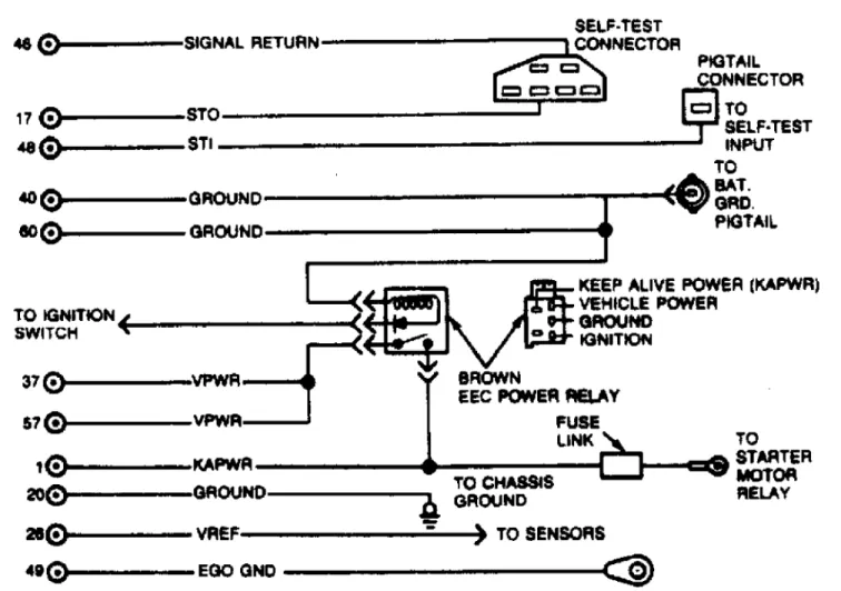
3) With breakout box installed and ECA connected, turn key off and wait 10 seconds. Set DVOM on 200-ohm scale. Measure resistance between test pins No. 40 and 46 and between test pins No. 46 and 60 at breakout box. If both readings are less than 5 ohms, go to next step. If readings are greater than 5 ohms, disconnect ECA connector and inspect for corrosion or damaged pins. Repair if necessary. If fault is still present, replace ECA and repeat QUICK TEST.
4) With breakout box installed and ECA connected, turn key off and wait 10 seconds. Set DVOM on 200-ohm scale. Measure resistance between test pin No. 46 at breakout box and signal return circuit in SELF-TEST connector. If reading is greater than 5 ohms, repair cause of resistance in signal return circuit. Repeat QUICK TEST. If readings is less than 5 ohms, go to next step.
5) Turn key on, leaving engine off. With ECA connected, set DVOM on 20-volt scale. Measure voltage between battery negative post and Keep Alive Power (KAPWR) circuit at EEC power relay. If reading is less than 10.5 volts, check KAPWR and vehicle power (V Power) circuits for shorts to ground. Also check KAPWR circuit from EEC power relay to battery positive post for open circuit. If reading is 10.5 volts or higher, go to next step.
6) Turn key on, leaving engine off. With ECA connected, set DVOM on 20-volt scale. Measure voltage between battery negative post and ignition circuit at EEC power relay. If readings is less than 10.5 volts, check for open ignition switch circuits. Repair wiring and repeat QUICK TEST. If reading is 10.5 volts or higher, go to next step.
7) Turn key off and wait 10 seconds. With ECA connected and DVOM on 200-ohm scale, measure resistance between battery negative post and EEC relay ground. If reading is greater than 5 ohms, repair wiring in ground circuit. Repeat QUICK TEST. If reading is less than 5 ohms, go to next step.
8) Turn key on, leaving engine off. With ECA connected and DVOM on 20-volt scale, measure voltage between battery negative post and VPWR circuit at EEC power relay. If reading is 10.5 volts or greater, repair open in VPWR circuit. If okay, repair short to ground in VPWR circuit. If reading is less than 10.5 volts, replace EEC power relay. Repeat QUICK TEST.
9) Turn key on, leaving engine off. Connect VOM or diagnostic tester to SELF-TEST connector. With SELF-TEST deactivated, enter
CONTINUOUS MONITOR (WIGGLE) TEST. Observe VOM or diagnostic tester for indication of fault while bending and twisting harness from EEC power relay to ECA.
10) If codes 72 or 78 are displayed or if fault is indicated, repair fault in vehicle power circuit. If codes 72 or 78 are not
displayed or if fault is not indicated, inspect EEC power relay and connectors for damaged pins, corrosion, etc. If okay, replace EEC power relay and repeat QUICK TEST.
Fig. 8: Vehicle Battery Circuits
TEST C - REFERENCE VOLTAGE
1) Disconnect ECA 60-pin connector. Inspect connector for damaged pins, corrosion, or loose wires. Repair if necessary. Install breakout box, leaving ECA disconnected. Turn key on, leaving engine off. Set DVOM on 20-volt scale and measure voltage between test pin No. 37 and signal return in SELF-TEST connector. If reading is less than 10.5 volts, go to CIRCUIT TEST B, step 1). If reading is 10.5 volts or higher, go to next step.
2) With breakout box installed and ECA connected, turn key on, leaving engine off. Set DVOM on 20-volt scale and measure voltage between test pins No. 26 and 46. If reading is 6.0 volts or more, go to step 4). If reading is 4.0 volts or less, go to step 5). If reading is between 4.0 and 6.0 volts, go to next step.
3) With breakout box installed and ECA disconnected, turn key off. Set DVOM on 200-ohm scale. Measure resistance from test pins No. 26 and 46 to suspect VREF sensor harness connector. If both readings are less than 5 ohms, VREF voltage is okay. Connect all sensors and repeat QUICK TEST. If any reading is 5 ohms or more, repair open circuit in VREF or signal return and then repeat QUICK TEST.
4) Turn key off and wait 10 seconds. With breakout box installed and ECA disconnected, turn key on, leaving engine off. Set DVOM on 20-volt scale and measure voltage between test pin No. 26 and battery ground. If reading is less than 0.5 volts, replace ECA and repeat QUICK TEST. If reading is 0.5 volts or higher, repair short to battery power in EEC harness. Repeat QUICK TEST. Replace ECA if fault still occurs.
5) Shorted TPS Sensor. Turn key off and wait for 10 seconds. With breakout box installed and ECA connected, disconnect Throttle Position Sensor (TPS) from vehicle harness. Turn key on, leaving
engine off. Set DVOM on 20-volt scale and measure voltage between test pins No. 26 and 46. If reading is 4.0 volts or more, replace TPS and repeat QUICK TEST. If less than 4.0 volts on models with EVP sensor, go to step 6). If reading is less than 4.0 volts on all other models, go to next step.
6) Shorted EVP Sensor. Turn key off and wait 10 seconds. With breakout box installed and ECA connected, disconnect EVP sensor. Turn key on, leaving engine off. Set DVOM on 20-volt scale. Measure voltage between test pins No. 26 and 46. If reading is 4.0 volts or more, replace EVP sensor and repeat QUICK TEST. If reading is less than 4.0 volts, go to next step.
7) Shorted MAP/BP Sensor. Turn key off and wait 10 seconds. With breakout box installed and ECA connected, disconnect MAP/BP sensor. Turn key on, leaving engine off. Set DVOM on 20-volt scale. Measure voltage between test pins No. 26 and 46. If reading is 4.0 volts or more, replace MAP/BP sensor and repeat QUICK TEST. If reading is less than 4.0 volts, go to next step.
8) With breakout box installed and ECA disconnected, turn key off and wait 10 seconds. Disconnect TPS, MAP and EVP sensor. Set DVOM on 200-ohm scale. Measure resistance between test pin No. 26 and test pins No. 20, 40, 46, and 60. If reading is less than 5 ohms, repair short to ground, connect all sensors. Repeat QUICK TEST. If original problem still occurs, replace ECA. Repeat QUICK TEST. If reading is 5 ohms or more, connect sensors, replace ECA and repeat QUICK TEST.
TEST D - VAT SENSOR
VANE AIR TEMPERATURE (VAT) SENSOR
Ambient air temperature must be at least 50
F (10
C) for test results to be valid. Avoid performing test in unusually hot or cold conditions.
VANE AIR TEMP (VAT) SENS RESISTANCE TABLE
Ambient Ohms Between
Temperature
F (
C) Test Pin 25 (1) & 46 32 (0) ... 5800 65 (18) ... 2700 185 (85) ... 300 220 (104) ... 180 240 (116) ... 125
1) Code 28 Displayed. Make sure ambient air temperature is at
least 50
F (10
C). If not, repeat QUICK TEST. If temperature is high enough, go to next step.
2) Turn key off and wait 10 seconds. Set DVOM on 20-volt scale. Disconnect Throttle Position Sensor (TPS). Turn key on, leaving engine off. Measure voltage at TPS connector between voltage reference (VREF) and signal return. If reading is less than 4.0 volts or more than 6.0 volts, go to CIRCUIT TEST C, step 1). If reading is between 4.0 and 6.0 volts, connect TPS and go to next step.
3) Turn key off and wait 10 seconds. Disconnect harness from airflow meter. Set DVOM on 200,000-ohm scale. Measure resistance at VAT sensor between VAT signal and signal return. If reading is from
125 ohms at 240
F (116
C) to 3700 ohms at 50
F (10
C), replace ECA. Connect airflow meter and repeat QUICK TEST. If reading is out of range, replace airflow meter and repeat QUICK TEST.
4) Code 58 Displayed. Turn key off and wait 10 seconds. Disconnect harness from airflow meter. Inspect for and repair any damaged wiring. Install a jumper wire between VAT signal and signal return at airflow meter connector. Perform KEY ON/ENGINE OFF SELF-TEST. If code 68 is displayed, replace airflow meter. Remove jumper wire, connect airflow meter, and repeat QUICK TEST. If code 68 is not displayed, remove jumper wire and go to next step.
5) Turn key off and wait 10 seconds. With jumper wire removed, leave airflow meter disconnected. Disconnect ECA 60-pin
connector. Inspect for and repair any damaged wiring. Install breakout box, leaving ECA disconnected. Set DVOM on 200-ohm scale. Measure resistance between test pin No. 25 and VAT signal at connector. Also measure resistance between test pin No. 46 and signal return at
connector. If both readings are less than 5 ohms, replace ECA. Remove breakout box and connect wiring to ECA and airflow meter. Repeat QUICK TEST. If either reading is 5 ohms or more, repair open circuit. Remove breakout box, connect wiring to ECA and airflow meter, and then repeat QUICK TEST.
6) Code 68 Displayed. Turn key off and wait 10 seconds. Disconnect harness from airflow meter. Inspect for and repair any damaged wiring. Perform KEY ON/ENGINE OFF (KOEO) SELF-TEST. If code 58 is displayed, replace airflow meter and connect harness. Repeat QUICK TEST. If code 58 is not displayed, go to next step.
7) Turn key off and wait 10 seconds. Set DVOM on 20-volt scale. Disconnect TPS. Turn key on, leaving engine off. Measure voltage between VREF and signal return at connector. If reading is less than 4.0 volts or more than 6.0 volts, go to CIRCUIT TEST C, step
1). If reading is between 4.0 and 6.0 volts, connect TPS and go to next step.
8) Turn key off and wait 10 seconds. Leave airflow meter disconnected. Disconnect ECA 60-pin connector. Inspect for and repair any damaged wiring. Install breakout box, leaving ECA disconnected. Set DVOM on 200,000-ohm scale. Measure resistance between test pin No. 25 and test pins No. 40, 46, and 60. If any reading is less than 10, 000 ohms, repair shorts. Remove breakout box, connect ECA and airflow meter. Repeat QUICK TEST. If all readings are 10,000 ohms or more, replace ECA. Remove breakout box. Connect ECA. Repeat QUICK TEST. 9) Continuous Code 58 or 68 Displayed. Using CONTINUOUS
MONITOR (WIGGLE) TEST, observe VOM or diagnostic tester for indication of fault while tapping VAT sensor lightly and wiggling connector. If fault is indicated, inspect connector and terminals. If connector and terminals are good, replace VAT sensor and repeat QUICK TEST. If no fault is indicated, go to next step.
10) While in CONTINUOUS MONITOR (WIGGLE) TEST, wiggle and bend EEC-IV harness from VAT sensor to firewall, a small section at a time. Also check harness from firewall to ECA. If fault is indicated, isolate fault and repair as necessary. Repeat QUICK TEST. If no fault is found, go to next step.
11) Turn key off and wait 10 seconds. Disconnect ECA 60-pin connector. Inspect both connector and connector terminals for obvious damage. If connectors and terminals are not okay, repair as necessary and repeat QUICK TEST. If connectors and terminals are okay, and you are unable to duplicate fault at this time, continuous code 58 or 68 testing is complete.
Fig. 10: VAT Sensor Circuit
TEST E - ACT SENSOR
AIR CHARGE TEMPERATURE (ACT) SENSOR
To prevent replacement of good components, be aware that the following non-EEC related areas may be at fault: cooling system, improper engine oil level, air cleaner duct problem. Ambient air
temperature must be at least 50
F (10
C) for test results to be valid. Avoid performing test in unusually hot or cold conditions.
AIR CHARGE TEMP (ACT) SENS RESISTANCE TABLE
Temperature
F (
C) Test Pin 25 & 46 50 (10) ... 58,750 65 (18) ... 40,500 180 (82) ... 3600 220 (104) ... 1840
1) Code 24 Displayed. For vehicles with ACT sensor mounted in intake manifold, go to next step. If sensor is properly mounted in air cleaner on all other models, go to next step. If sensor is not
properly mounted, install ACT sensor properly and repeat QUICK TEST. 2) Turn key off and wait 10 seconds. Set DVOM on 20-volt scale and disconnect Throttle Position Sensor (TPS). Turn key on, leaving engine off. Measure voltage between VREF and signal return at TPS connector. If reading is less than 4.0 volts or more than 6.0 volts, go to CIRCUIT TEST C, step 1). If reading is between 4.0 and 6. 0 volts, connect TPS and go to next step.
3) Start engine and make sure that engine reaches normal operating temperature. Turn key off and wait 10 seconds. Disconnect ACT sensor, set DVOM on 200,000-ohm scale, and measure ACT sensor resistance. If reading is less than 1100 ohms or more than 58,000 ohms, check function of heat stove duct valve. If valve is operating correctly, replace ACT sensor, connect ACT sensor, and repeat QUICK TEST. If reading is between 1100 and 58,000 ohms, go to next step. 4) Turn key off. Disconnect ACT sensor harness. Set DVOM on 200,000-ohm scale and run engine for 2 minutes. While engine is
running, measure ACT sensor resistance. If reading is between 2400 and 29,000 ohms, replace ECA, connect ACT harness, and repeat QUICK TEST. If reading is less than 2400 ohms or more than 29,000 ohms, check function of heat stove duct valve. If valve works properly, replace ACT sensor. Repeat QUICK TEST.
5) Code 54 Displayed. Turn key off and wait 10 seconds. Disconnect ACT sensor harness. Inspect for and repair any damaged wiring. Install a jumper wire between ACT signal and signal return at connector. Perform KEY ON/ENGINE OFF (KOEO) SELF-TEST. If code 64 is displayed, replace ACT sensor. Remove jumper wire, connect ACT sensor, and repeat QUICK TEST. If code 64 is not displayed, remove jumper wire and go to next step.
6) Turn key off and wait 10 seconds. Leave ACT sensor harness disconnected. Disconnect ECA 60-pin connector. Inspect for and repair any damaged wiring. Install breakout box, leaving ECA disconnected. Set DVOM on 200-ohm scale. Measure resistance between test pin No. 25 and ACT signal at ACT connector, and between test pin No. 46 and
signal return at ACT connector. If both readings are less than 5 ohms, replace ECA and remove breakout box. Connect ECA and ACT sensor, and then repeat QUICK TEST. If either reading is 5 ohms or more, repair opens in circuit. Remove breakout box, and connect ECA and ACT sensor. Repeat QUICK TEST.
7) Code 64 Displayed. Turn key off and wait 10 seconds. Disconnect ACT sensor. Inspect for and repair any damaged wiring. Perform (KOEO) SELF-TEST. If code 54 is displayed, replace ACT sensor, connect harness, and repeat QUICK TEST. If code 54 is not displayed, go to next step.
8) Turn key off and wait 10 seconds. Set DVOM on 20-volt scale and disconnect TPS. Turn key on, leaving engine off. Measure voltage between VREF and signal return at TPS connector. If reading is less than 4.0 volts or more than 6.0 volts, go to CIRCUIT TEST C, step 1). If reading is between 4.0 and 6.0 volts, connect TPS and go to next step.
9) Turn key off and wait 10 seconds. Disconnect harness at ACT sensor. Disconnect ECA 60-pin connector. Inspect for and repair any damaged wiring. Install breakout box and set DVOM on 200,000-ohm
scale. Measure resistance between test pin No. 25 and test pins No. 40, 46, and 60. If any reading is less than 10,000 ohms, repair shorts. Remove breakout box, and connect ECA and ACT sensor. Repeat QUICK TEST. If all readings are 10,000 ohms or more, replace ECA. Remove breakout box, and connect ECA and ACT sensor. Repeat QUICK TEST.
10) Continuous Code 54 or 64 Displayed. Using CONTINUOUS MONITOR (WIGGLE) TEST, observe VOM or diagnostic tester for indication of fault while tapping ACT sensor lightly and wiggling connector. If fault is indicated, inspect connector and terminals. If connector and terminals are good, replace ACT sensor and repeat QUICK TEST. If no fault is indicated, go to next step.
11) While in CONTINUOUS MONITOR (WIGGLE) TEST, wiggle and bend small sections of harness from ACT sensor to firewall. Repeat action from firewall to ECA. If fault is indicated, isolate fault and repair as necessary. Repeat QUICK TEST. If no fault is indicated, go to next step.
12) Turn key off and wait 10 seconds. Disconnect ECA 60-pin connector. Inspect both connector and connector terminals for obvious damage. If connectors and terminals are not okay, repair as necessary and repeat QUICK TEST. If connectors and terminals are okay, and you are unable to duplicate fault at this time, continuous code 54 or 64 testing is complete.
Fig. 11: Air Charge Temperature (ACT) Sensor Circuit
TEST F - EVP/EGRC/EGRV
EGR VALVE POSITION (EVP) SENS, EGR CTRL (EGRC) SOLENOID & EGR
VENT (EGRV) SOLENOIDTo prevent replacement of good components, be aware that the following non-EEC related area may be at fault: damaged EGR valve. NOTE: The 5.0L SEFI does not use either an EGRC or an EGRV. When following these steps, ignore references to the EGRC and EGRV, but follow the procedures for the EVP.
1) Code 31 Displayed. Turn key off and wait 10 seconds. Disconnect and plug vacuum line at EGR valve. Perform KEY ON/ENGINE RUNNING (KOER) SELF-TEST. If code 31 is not displayed but codes 32 and 34 are, go to step 8). If code 31 is displayed, go to next step.
2) Turn key off and wait 10 seconds. Leave EGR vacuum line disconnected and plugged. Disconnect EVP sensor harness. Set DVOM on 200,000-ohm scale and connect vacuum pump to EGR valve. Measure resistance between EVP signal and VREF at EVP connector while vacuum is slowly increased to 10 in. Hg. If reading is less than 100 ohms or more than 5500 ohms, replace EVP sensor, connect vacuum signal line
and harness. Repeat QUICK TEST. If reading does not decrease or valve does not hold vacuum, go to step 14). If reading gradually decreases from a maximum of 5500 ohms to a minimum of 100 ohms, go to next step. 3) Turn key on, leaving engine off. Disconnect and plug
vacuum signal line and disconnect EVP sensor harness. Set DVOM on 20-volt scale. Measure 20-voltage between VREF and signal return at EVP connector. If reading is less than 4.0 volts or more than 6.0 volts, go to CIRCUIT TEST C, step 1). If reading is between 4.0 and 6.0 volts, go to next step.
4) Turn key off and wait 10 seconds. Disconnect harness at EVP sensor and ECA 60-pin connector. Inspect for and repair any damaged wiring. Install breakout box, leaving ECA disconnected. Set DVOM on 200-ohm scale. Measure resistance between test pin No. 27 and EVP signal at EVP connector. If reading is 5 ohms or more, repair open in circuit. Remove breakout box, connect ECA and EVP sensor, and then repeat QUICK TEST. If reading is less than 5 ohms, go to next step. 5) Turn key off and disconnect harness at EVP sensor. Install breakout box, leaving ECA disconnected. Set DVOM on 200,000-ohm scale. Measure resistance between test pin No. 27 and test pins No. 26, 40, 46, and 60. If any reading is less than 10,000 ohms, repair short circuit. Remove breakout box, connect ECA and EVP sensor, then repeat QUICK TEST. If all readings are 10,000 ohms or more, go to next step. 6) Turn key off and wait 10 seconds. Connect known good EVP sensor and EGR valve assembly to harness and vacuum lines. Remove breakout box and connect ECA. Perform KEY ON/ENGINE OFF SELF-TEST. If code 31 is displayed, replace ECA. Connect original EVP sensor and EGR valve assembly. Repeat QUICK TEST. If code 31 is not displayed, go to next step.
7) Turn key off and wait 10 seconds. Install original EVP sensor to known good EGR valve. Connect EVP sensor. Perform KEY ON/ENGINE OFF (KOEO) SELF-TEST. If code 31 is displayed, replace EVP sensor. Repeat QUICK TEST. If code 31 is not displayed, service EGR system.
8) Codes 32, 33, or 34 Displayed. Use DVOM for this step. Do not use diagnostic tester. Turn key off and wait 10 seconds. Set DVOM on 20-volt scale. Connect DVOM negative test lead to STO and positive lead to battery positive post. Connect jumper wire between STI and signal return. Perform (KOEO) TEST until end of CONTINUOUS SELF-TEST codes (DVOM reads 0 volts). Depress and release throttle. If reading does not change to high voltage, depress throttle to WOT and release. If STO voltage does not go high, go to CIRCUIT TEST PP, step 12). If DVOM reading does go high, stay in OUTPUT STATE CHECK and go to next step.
9) Turn key on, leaving engine off. Stay in OUTPUT STATE CHECK. Set DVOM to 20-volt scale. Connect DVOM between EGRV solenoid, VPWR and EGRV signal. Depress and release throttle several times to cycle output on and off while observing DVOM. Repeat check for EGRC solenoid, VPWR and EGRC signal. If either solenoid does not cycle on and off, exit OUTPUT STATE CHECK and go to step 15). If both solenoids cycle on and off, stay in OUTPUT STATE CHECK and go to next step. 10) Turn key on, leaving engine off. Stay in OUTPUT STATE CHECK. Disconnect and plug vacuum line from bottom port of EGRC solenoid. Connect vacuum pump to open port. Connect vacuum gauge in common output (upper) vacuum line to EGR valve. Disconnect, but DO NOT plug vacuum vent line from EGRV solenoid. Maintain source vacuum and cycle output on and off by depressing and releasing throttle.
11) If vacuum does not cycle on and off in less than 2 seconds, check solenoid filter for obstructions, and replace if necessary. If filter is okay, replace solenoid assembly. After repairs, connect all vacuum lines and repeat QUICK TEST. If vacuum output cycles on and off in less than 2 seconds, connect all vacuum lines and go to next step.
lines, and check vacuum lines for proper routing, kinks, cracks, obstructions, leaks, etc. Use vehicle emissions decal as a guide. If vacuum lines are not okay, repair as necessary and repeat QUICK TEST. If vacuum lines are okay, go to next step.
13) With key off, disconnect EVP sensor harness. Inspect for and repair any damaged wiring. Set DVOM on 200,000-ohm scale.
Disconnect vacuum line at EGR valve and connect vacuum pump to valve. Measure resistance of EVP sensor between EVP signal and VREF terminals while increasing vacuum to 10 in. Hg. If reading slowly decreases from maximum of 5500 ohms to minimum of 100 ohms, replace ECA. Connect EVP sensor and EGR vacuum line. Repeat QUICK TEST. If reading does not slowly decrease, go to next step.
14) With key off, disconnect EVP sensor harness. Remove EVP sensor and vacuum line from EGR valve. Measure resistance of EVP sensor between EVP signal and VREF terminals. Observe resistance changes as EVP sensor shaft is slowly pushed in and slowly released. If both readings increase and decrease smoothly in range of 100-5500 ohms, replace EGR valve assembly. Connect EVP sensor and EGR vacuum line. Repeat QUICK TEST. If either reading changes abruptly during range of 100-5500 ohms, replace EVP sensor. Reconnect harness and EGR vacuum line. Repeat QUICK TEST.
NOTE: It is normal for EVP sensor total resistance to drop below 100 ohms when disconnected from EGR valve. A defective sensor will change resistance suddenly between 5500 and 100 ohms.
15) Turn key off and wait 10 seconds. Set DVOM on 200-ohm scale. Disconnect EGRC and EGRV solenoids from harness. Inspect for and repair any damaged wiring. Measure resistance of both solenoids. If either reading is less than 30 ohms or more than 70 ohms, replace EGRC/EGRV solenoid assembly. Repeat QUICK TEST. If both readings are between 30 and 70 ohms, reconnect solenoids and go to next step.
16) Disconnect EGRC and EGRV solenoids from harness. Turn key on, leaving engine off. Set DVOM on 20-volt scale. Measure voltage between battery negative terminal and VPWR circuit for both solenoids. If either reading is less than 10.5 volts, repair open circuit and repeat QUICK TEST. If both readings are 10.5 volts or more, go to next step.
17) Turn key off and wait 10 seconds. Leave EGRC and EGRV solenoids disconnected. Disconnect ECA 60-pin connector. Inspect for and repair any damaged wiring. Install breakout box, leaving ECA disconnected. Set DVOM on 200-ohm scale. Measure resistance between test pin No. 33 and EGRV signal at EGRV solenoid connector. Measure resistance between test pin No. 52 and EGRC signal at EGRC solenoid connector. If either reading is 5 ohms or more, repair open circuit. Remove breakout box, connect ECA and solenoids, then repeat QUICK TEST. If both readings are less than 5 ohms, go to next step.
18) Turn key off and wait 10 seconds. Set DVOM on 200,000-ohm scale. Install breakout box, leaving ECA disconnected. Disconnect EGRC and EGRV solenoids. Measure resistance between test pin No. 33 and/or 52 and test pins No. 40, 46, and 60. If readings are less than 10,000 ohms, repair short to ground. Repeat QUICK TEST. If readings are 10, 000 ohms or more, go to next step.
19) With key off, disconnect EGRC and EGRV solenoids from harness. Install breakout box, leaving ECA disconnected. Set DVOM on 200,000-ohm scale. Measure resistance between test pin No. 33 and test pins No. 37 and 57. Measure resistance between test pin No. 52 and test pins No. 37 and 57. If any reading is less than 10,000 ohms, repair short in circuit. Remove breakout box and connect ECA. Repeat QUICK TEST. If code is repeated, replace ECA. If all readings are 10, 000 ohms or more, replace ECA. Remove breakout box and connect ECA. Repeat QUICK TEST.
20) Code 35 Displayed. This code indicates that engine RPM is too low for correct EGR testing. If code 12 is also displayed, go to: * CIRCUIT TEST DD, step 1) for EFI models with air by-pass. * CIRCUIT TEST EE, step 1) for models with an idle speed control motor.
If code 12 is not displayed with code 35, go to next step.
21) Turn key off and wait 10 seconds. Install tachometer. Perform (KOER) SELF-TEST at 1500 RPM. Record (KOER) service codes. If code 35 is displayed, replace ECA and repeat QUICK TEST. If code 35 is not displayed, repeat QUICK TEST and repair codes as necessary.
22) Continuous Code 31 Displayed. Using CONTINUOUS MONITOR (WIGGLE) TEST, observe VOM or diagnostic tester for indication of fault while doing the following: connect vacuum pump to EGR valve. Very slowly apply 6 in. Hg vacuum to EGR valve. Bleed vacuum slowly and lightly tap on EVP sensor. Wiggle EVP sensor connector. If fault is indicated, go to next step. If no fault is indicated, go to step 24).
23) Turn key off and wait 10 seconds. Disconnect ECA 60-pin connector. Inspect for and repair any damaged wiring. Install breakout box and connect ECA. Stay in CONTINUOUS MONITOR (WIGGLE) TEST. Connect DVOM between test pins No. 27 and 46. Set DVOM on 20-volt scale. Turn key on, leaving engine off. Repeat step 22) while watching voltage. If fault occurs below 4.25 volts, disconnect EVP sensor from harness. Inspect for and repair any damaged wiring. If wiring is good, replace EVP sensor. Repeat QUICK TEST. If fault does not occur below 4.25 volts, EGR valve overshoot may have caused continuous code 31. Sensor test is complete. Go to next step for harness test.
24) While in CONTINUOUS MONITOR (WIGGLE) TEST, bend, shake, and wiggle small sections of EEC-IV harness from sensor to firewall and from firewall to ECA. If fault is indicated, isolate fault and repair as necessary. Repeat QUICK TEST. If no fault is indicated, go to next step.
25) Turn key off and wait 10 seconds. Disconnect ECA 60-pin connector. Inspect both connector and terminals for obvious damage. If connector and terminals are damaged, repair as necessary, then repeat QUICK TEST. If connector and terminals are okay, fault cannot be duplicated at this time. Continuous code 31 testing is complete.
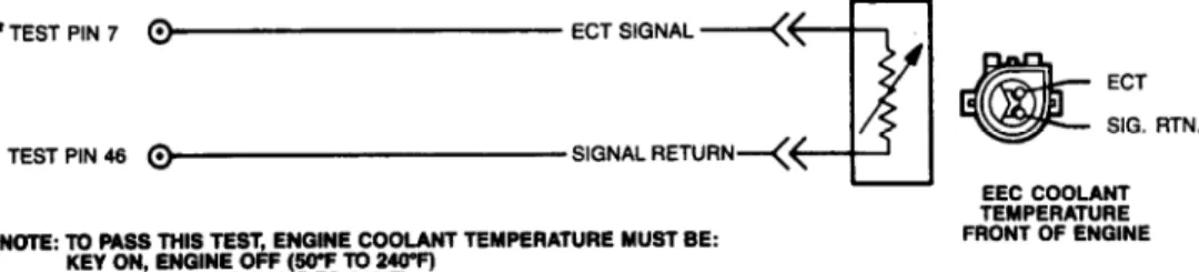
TEST G - ECT SENSOR
ENGINE COOLANT TEMPERATURE (ECT) SENSOR
NOTE: For purposes of this test, a "warmed up" engine has a
coolant temperature of 50-240
F (10-116
C) for KEY ON/ENGINE
OFF (KOEO) SELF-TEST and 180-240
F (82-116
C) for KEY ON/ENGINE RUNNING (KOER) SELF-TEST. The test procedure will be invalid outside these ranges.
COOLANT TEMP (ECT) SENS RESISTANCE TABLE
Ambient Ohms Between
Temperature
F (
C) Test Pins No. 7 & 46 50 (10) ... 58,750 65 (18) ... 40,500 180 (82) ... 3600 220 (104) ... 1840
To prevent replacement of good components, be aware that the following non-EEC related areas may be at fault: coolant or oil level, blocked or obstructed air flow, engine not at normal operating
temperature, or cooling fan.
1) Code 21 Displayed. Start engine and run it at 2000 RPM for 2 minutes. Check that upper radiator hose is hot and pressurized. Repeat QUICK TEST before continuing. If vehicle stalls, DO NOT service code 21 at this time, go directly to DIAGNOSIS BY SYMPTOM TEST. If code 21 is not displayed, service other codes as necessary (if displayed). If code 21 appears, go to next step.
2) Turn key off and wait 10 seconds. Disconnect TPS. Set DVOM on 20-volt scale. Turn key on, leaving engine off. Measure voltage at TPS harness connector between VREF and signal return. If voltage is less than 4.0 volts or more than 6.0 volts, go to CIRCUIT TEST C, step 1). If voltage is between 4 and 6 volts, reconnect TPS and go to next step.
3) Make sure engine is fully warmed up for this step. Turn key off and wait 10 seconds. Disconnect wiring harness at ECT sensor. Set DVOM on 200,000-ohm scale and measure resistance of ECT sensor. If
reading is 1300-7700 ohms at engine coolant temperature of 240-140
F
(116-60
C) with engine off and 1550-4550 ohms at 230-180
F (110-82
C) with engine running, replace ECA, connect ECT sensor, then repeat QUICK TEST. If readings are not correct for coolant temperature, replace ECT sensor, connect harness, and repeat QUICK TEST. 4) Code 51 Displayed. Turn key off and wait 10 seconds. Disconnect ECT sensor at wiring harness and inspect wiring for damage or corrosion. Connect a jumper wire between ECT signal and signal return terminals in sensor harness connector. Repeat KEY ON/ENGINE OFF (KOEO) SELF-TEST. If code 61 is displayed, replace ECT sensor and remove jumper wire. Reconnect harness to ECT sensor and repeat QUICK TEST. If code 61 is not displayed, go to next step.
5) Turn key off and wait 10 seconds. With harness
disconnected at ECT sensor and jumper removed from harness connector, disconnect ECA 60-pin connector. Inspect for and repair any damaged wiring. Install breakout box, leaving ECA disconnected. Set DVOM on 200-ohm scale. Measure resistance between ECT signal at ECT connector and test pin No. 7. Measure resistance between signal return at ECT connector and test pin No. 46. If both readings are less than 5 ohms, replace ECA. Remove breakout box and connect ECA and ECT sensor. Repeat QUICK TEST. If either reading is 5 ohms or more, repair open
circuits. Remove breakout box, and connect ECA and ECT sensor. Repeat QUICK TEST.
6) Code 61 Displayed. Turn key off and wait 10 seconds. Disconnect ECT sensor and inspect connector for damage or corrosion. Repair wiring and repeat KOEO SELF-TEST. If code 51 is displayed, replace ECT sensor, connect sensor, then repeat QUICK TEST. If code 51 is not displayed, go to next step.
7) Turn key off and wait 10 seconds. Set DVOM on 20-volt scale. Disconnect TPS. Turn key on, leaving engine off. Measure
voltage between VREF and signal return at TPS connector. If reading is less than 4.0 volts or more than 6.0 volts, go to CIRCUIT TEST C, step 1). If voltage is between 4.0 and 6.0 volts, connect TPS and go to next step.
8) Turn key off and wait 10 seconds. Disconnect harness from ECT sensor. Disconnect ECA 60-pin connector. Inspect for and repair any damaged wiring. Install breakout box, leaving ECA disconnected. Set DVOM on 200,000-ohm scale. Measure resistance between test pin No. 7 and test pins No. 40, 46, and 60. If any reading is less than 10,000 ohms, repair short circuits. Remove breakout box, connect ECA and ECT sensor, then repeat QUICK TEST. If all readings are 10,000 ohms or more, replace ECA. Remove breakout box, connect ECA and ECT sensor. Repeat QUICK TEST.
9) Continuous Code 21 Displayed. Turn key off and wait 10 seconds. Disconnect all SELF-TEST equipment. Prepare vehicle for test drive. While driving vehicle, attempt to copy driving style in which complaint was noticed. If problem occurs, try to maintain condition for one or more minutes. After road test, repeat KOEO SELF-TEST. If code 21 is present in CONTINUOUS SELF-TEST, make sure that thermostat is working properly. If thermostat functions properly, replace ECT sensor. Repeat QUICK TEST. If code 21 is not displayed, fault cannot be duplicated at this time. Continuous code 21 testing is complete. 10) Continuous Code 51 or 61 Displayed. Using CONTINUOUS MONITOR (WIGGLE) TEST, observe VOM or diagnostic tester for indication of fault while tapping ECT sensor and wiggling ECT connector. If fault is indicated, disconnect and inspect ECT connector and terminals. If connector and terminals are okay, replace ECT sensor and repeat QUICK TEST. If no fault is indicated, go to next step.
11) While in CONTINUOUS MONITOR (WIGGLE) TEST, observe VOM or diagnostic tester for indication of fault as you bend, shake or wiggle EEC-IV harness. Start at sensor connector and work toward firewall. Also test harness from firewall to ECA in same manner. If fault is indicated, isolate fault in wiring and repair as necessary. Repeat QUICK TEST. If fault is not indicated, go to next step.
12) Turn key off and wait 10 seconds. Disconnect ECA 60-pin connector. Inspect both connectors and terminals for obvious damage. If connectors and terminals are damaged, repair as necessary and
repeat QUICK TEST. If connectors and terminals are okay, fault cannot be duplicated at this time. Continuous code 51 or 61 testing is
complete.
Fig. 13: Engine Coolant Temperature (ECT) Sensor Circuit
TEST H - MAP SENSOR
MANIFOLD ABSOLUTE PRESSURE (MAP) SENSOR
NOTE: Barometric pressure sensor output is digital and must be measured with MAP/BP tester.
To prevent replacement of good components, be aware that the following non-EEC related areas may be at fault: unusually high/low atmospheric barometer reading, kinked or blocked vacuum lines, engine condition (valves, vacuum leaks, valve timing, EGR valve, etc.). 1) Code 22 Displayed, Engine Off. Turn key off. Disconnect MAP sensor from harness. Connect MAP/BP tester between wiring harness and MAP sensor. Connect banana plugs of tester into DVOM and set DVOM on 20-volt scale. See MAP/BP Tester Hook-Up. Go to next step.
Fig. 14: MAP/BP Tester Hook-Up
2) With MAP/BP tester connected, turn key on. If only Green light on tester is lit, VREF is correct. Go to step 4). If "LESS THAN 4 VOLTS" Red light or no lights come on, VREF is too low. If "MORE THAN 6 VOLTS" Red light comes on, VREF is too high. If VREF is too high or too low, go to next step.
3) With MAP/BP tester connected, turn key on. Disconnect MAP sensor and repeat step 2). If only Green light comes on, VREF is
correct. Replace MAP sensor. Repeat QUICK TEST. If "LESS THAN 4 VOLTS" Red light or no lights come on, VREF is too low. If "MORE THAN 6
VOLTS" Red light comes on, VREF is too high. If VREF is too high or too low, remove MAP/BP tester, connect sensor, then go to CIRCUIT TEST C, step 1).
4) With MAP/BP tester connected and key on, measure sensor output voltage. If voltage output is in correct range for altitude of vehicle being tested, remove MAP/BP tester and go to next step. If output reading is outside range, remove MAP/BP tester and go to step 6).
NOTE: Measure several known good MAP sensors on available vehicles. Mean voltage reading will be typical for your location on date of testing.
MAP VOLTAGE OUTPUT SPECIFICATIONS TABLE
Elevation (Ft.) Voltage Output (Volts) 0 ... 1.55-1.63 1000 ... 1.52-1.60 2000 ... 1.49-1.57 3000 ... 1.46-1.54 4000 ... 1.43-1.51 5000 ... 1.40-1.48 6000 ... 1.37-1.45 7000 ... 1.35-1.43
5) Turn key off and wait 10 seconds. Disconnect MAP sensor from harness. Disconnect ECA 60-pin connector. Inspect for and repair any damaged wiring. Install breakout box, leaving ECA disconnected. Set DVOM on 200-ohm scale. Measure resistance between MAP signal at sensor connector and test pin No. 45. If reading is less than 5 ohms, replace ECA. Connect ECA and MAP sensor and repeat QUICK TEST. If reading is 5 ohms or higher, repair opens in wiring. Remove breakout box, connect ECA and MAP sensor. Repeat QUICK TEST.
6) Turn key off and wait 10 seconds. Disconnect ECA 60-pin connector. Inspect for and repair any damaged wiring. Install breakout box, leaving ECA disconnected. Disconnect harness at MAP sensor. Set DVOM on 200,000-ohm scale. Measure resistance between test pin No. 45 and test pins No. 26, 46, 40, and 60. If any reading is less than 10, 000 ohms, repair shorts in wiring. Remove breakout box and connect ECA and MAP sensor. Repeat QUICK TEST. If all readings are 10,000 ohms or more, replace MAP sensor. Remove breakout box and connect all wiring. Repeat QUICK TEST.
7) Code 22 Displayed, KEY ON/ENGINE RUNNING (KOER) . Check to see if service codes 31, 32, 33, 34 or 35 are present. If so, go to KOER SELF-TEST table and perform appropriate CIRCUIT TEST. If not, go to next step.
8) Turn key off and wait 10 seconds. Disconnect vacuum hose from MAP sensor. Connect vacuum pump to MAP sensor and apply 18 in. Hg. vacuum to sensor. If sensor does not hold vacuum, replace sensor, connect vacuum line and repeat QUICK TEST. If MAP sensor does hold vacuum, release vacuum and go to next step.
9) Turn key off and wait 10 seconds. Plug vacuum hose going to MAP sensor. Start engine and run at 1400-1700 RPM. Slowly apply 15 in. Hg. vacuum to MAP sensor. With engine under these operating
conditions, perform KOER SELF-TEST. If code 22 is still present, replace MAP sensor. If code 22 is no longer displayed, inspect vacuum hose going to MAP sensor. If okay, service other codes. If there are none, check engine for cause of low vacuum.
10) Code 72 Displayed. Turn key off and wait 10 seconds. Install vacuum gauge with "T" in manifold vacuum line at MAP sensor. Perform KOER SELF-TEST and observe vacuum reading before and during DYNAMIC RESPONSE CHECK portion of test. Record service codes. If vacuum decreased 10 in. Hg or more and code 72 is not displayed, disconnect vacuum gauge and service other codes as necessary. If vacuum decreased 10 in. Hg and code 72 is displayed, replace MAP
sensor and repeat QUICK TEST. If vacuum decreased less than 10 in. Hg, go to next step.
11) Check vacuum lines for correct routing, using vehicle emissions decal as a guide. Also check MAP sensor vacuum lines for kinks or blockage. If lines are good, EEC-IV system is okay. Check engine for cause of low vacuum. If vacuum lines are bad, repair as necessary and repeat step 9).
12) Turn key off. Disconnect MAP sensor from harness. Connect MAP/BP tester between wiring harness and MAP sensor. Connect banana plugs of tester into DVOM and set DVOM on 20-volt scale. See MAP/BP Tester Hook-Up. Go to next step.