Avaya Solution & Interoperability Test Lab
Application Notes for Configuring Avaya Aura
®Contact
Center R6.2 with Avaya Communication Server 1000E R7.5
via the Application Module Link interface - Issue 1.0
Abstract
These Application Notes describe how to configure Avaya Aura® Contact Center R6.2 to work with Avaya Communication Server 1000E R7.5 over the Application Module Link.
Avaya Aura® Contact Center can connect with Avaya Communication Server 1000E using a proprietary protocol called Application Module Link.
Information in these Application Notes has been obtained through Solution and Interoperability Lab full stack testing and additional technical discussions.
Table of Contents
1. Introduction ... 4
1.1. Avaya Aura® Contact Center Overview ... 4
2. Interoperability Testing ... 6
2.1. Test Description and Coverage ... 6
2.2. Test Results and Observations ... 6
3. Reference Configuration ... 7
4. Equipment and Software Validated ... 8
5. Configuration of Avaya Communication Server 1000E ... 9
5.1. Connecting to the CS1000E using PuTTY ... 9
5.2. Define the ELAN on CS1000E ... 11
5.3. Configuring the CS1000E System Parameters... 12
5.4. Enabling the ELAN link ... 12
5.5. Defining a default gateway address ... 13
5.6. Configuring an ACD queue... 13
5.7. Configuring the CDN on the CS1000E ... 13
5.8. Configure the Agent telephone sets ... 14
5.9. Configure zones for IP sets ... 14
5.10. Configure an 1100 series IP Supervisor/Agent telephone set ... 15
5.11. Configure an 1100 series IP Agent telephone set ... 16
5.12. Configure an 1200 series IP Agent telephone set ... 17
5.13. Configure a 2050 IP Soft-phone Agent telephone set ... 17
5.14. Configure a 3900 series TDM Agent telephone set ... 18
6. Configuration on Avaya Aura® Contact Center ... 19
6.1. Verify that all AACC services are running ... 19
6.2. Logon to Contact Center Manager Administration ... 26
6.3. Add the Contact Center Manager Server to CCMA ... 27
6.4. Add the Communication Control Toolkit to CCMA ... 30
6.5. Configure the CS1000E service provider... 35
6.6. Importing CS1000E Data ... 39
6.7. Configure the CDN on CCMS ... 47
6.8. Configure the IVR-ACD DNs ... 50
6.9. Configure the Phonesets and Voiceports ... 52
6.12. Assigning Resources in CCT ... 68
6.13. Configure a basic script using Orchestration Designer ... 72
7. Verification Steps ... 81
7.1. Verifying the Agent sets after they have been acquired by AACC ... 81
7.2. Verifying CCT using the Reference Client ... 84
7.3. Verifying the Contact Center operation using Avaya Aura® Agent Desktop ... 88
8. Conclusion ... 92
9. References ... 92
1. Introduction
Avaya Aura® Contact Center (AACC) is a robust, software only solution that facilitates agents and knowledge workers to efficiently and effectively collaborate with customers and partners across multiple media types to manage customer experience. A typical Avaya Aura® Contact Center installation (see the Reference Configuration in Figure 1 below) consists of multiple software components installed and configured on industry standard servers.
Avaya Communication Server 1000E (CS1000E) is an IP-distributed telephony communications system that delivers the benefits of network convergence and collaborative communications, providing the foundation for a unified communications environment.
These Application Notes will document the procedures necessary to configure an Avaya Aura® Contact Center 6.2 (Standard Availability) system to work with Avaya Communication Server 1000E 7.5 over the proprietary Application Module Link (AML) protocol.
This Application Note describes a sample configuration for Avaya Aura® Contact Center with CS1000E over AML. Detailed administration of other aspects of Avaya Aura® Contact Center, CS1000E or additional equipment installed to support the AACC installation (e.g. Active Directory / Domain Name Servers, Voice / Data Network equipment) will not be described as it is outside the scope of this Application Note.
Steps described in this document include:
1. Configuration on the CS1000E for the Control Directory Number (CDN) and Automatic Call Distribution (ACD) queue to facilitate the routing of customer calls over AML to the AACC. AACC then provides call treatments, skill-based routing and reporting.
2. Configuration on CS1000E for the Agent phones (controlled by AACC and associated with Agent Desktop clients).
3. Configuration of the AACC using the Contact Center Manager Administration (CCMA) web interface to add the Contact Center Manager Server (CCMS) and Communication Control Toolkit (CCT) server to the CCMA database.
4. Importing the CDN data and Agent phone data from CS1000E into AACC, configuration on AACC for the CDN and the mapping of the phones to the relevant Agents on AACC. 5. Configuration of a basic script on AACC using the Orchestration Designer toolkit which
will allow calls to be routed to logged on and available agents.
1.1. Avaya Aura
®Contact Center Overview
Below is a brief description of the important applications of Avaya Aura® Contact Center: Contact Center Manager Server (CCMS) is a core component that provides intelligent routing capability for voice and multimedia contacts to route contacts to the most
qualified agent. The most qualified agent is the agent with the appropriate ability to handle the type of contact.
Communication Control Toolkit (CCT) is the contact control component that facilitates the Computer Telephony Integration (CTI) for Agent call control.
Contact Center License Manager (LM) is used for central licensing and control of all Contact Center components and features across the Contact Center suite (Contact Center Manager Server, Contact Center Manager Administration, Communication Control Toolkit, and Contact Center Multimedia).
Contact Center Manager Server Utility (CCMSU) is used to monitor and maintain Contact Center Manager Server. The Contact Center Manager Server Utility provides functionality that is not available through Contact Center Manager Administration. Contact Center Multi-Media (CCMM) is an optional component that manages all multi-media contacts into and out of the contact center. These contacts include email, web-chat and instant messaging.
Avaya Aura Agent Desktop (AAAD) is the Agent’s desktop client used to manage the customer contacts (voice and multi-media).
While there are many different supported Avaya Aura® Contact Center configurations, these Application Notes will discuss an AML-based Standard Availability installation. In a Standard Availability configuration, Avaya Aura® Contact Center R6.2 server applications are installed co-resident on a single server running Windows Server 2008 R2 64-bit Standard / Enterprise edition operating system. The following is a list of the core applications and the install specification.
AML based Avaya Aura® Contact Center Applications Installed co-resident on the same server
Contact Center Manager Server (CCMS) Communication Control Toolkit (CCT)
Contact Center Manager Administration (CCMA)
Contact Center Multimedia (CCMM) – optional component
It is assumed that the Avaya Communication Server 1000E 7.5 has already been installed and working with an appropriate license to enable the relevant software packages and with the latest software patches (refer to Appendix B below for details from the sample configuration). It is also assumed that the Avaya Aura® Contact Center software has already been installed and that any other relevant infrastructure has been provisioned (e.g. Active Directory / Domain Name Servers, Voice / Data Network equipment).
2. Interoperability Testing
These application notes just describe the procedures necessary to configure an Avaya Aura® Contact Center 6.2 (Standard Availability) system to work with Avaya Communication Server 1000E 7.5 (High Availability) over the proprietary Application Module Link (AML) protocol.
2.1. Test Description and Coverage
It is presumed that the Avaya Aura® Contact Center 6.2 (Standard Availability) software has been pre-installed on Windows Server 2008 Release 2 64-bit Standard or Enterprise edition running on a Dell PowerEdge R610 server. It is also presumed that the Avaya Communication Server 1000E Release 7.5 system and software have also been provisioned with the most recent dependency patch lists.
2.2. Test Results and Observations
The following observations and outcomes are brought to the attention of users to highlight unexpected actions observed when generating these Application Notes.
As mentioned in Section 6.5, when configuring the CS1000E service provider using the CCT Console there is an error in the drop-down menu for the CS1000 Software Release. The options offered in this drop-down menu do not currently include Release 7.5. The recommended option to use is Release 7.0 even though the CS1000E is on Release 7.5.
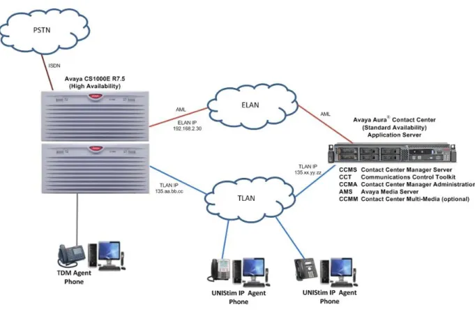
3. Reference Configuration
The following diagram (Figure 1) shows the Reference configuration used for testing. It depicts a typical AML-based Avaya Aura® Contact Center configuration with Avaya Communications Server 1000E and associated contact center agent equipment.
Figure 1: Typical Avaya Aura® Contact Center Configuration
The procedures discussed in the following sections only apply to servers and applications which are core elements of Avaya Communications Server 1000E and Avaya Aura® Contact Center (as shown in the diagram).
4. Equipment and Software Validated
The following equipment and software were used for the reference configuration provided:
Equipment/Software Release/Version
Avaya Aura® Contact Centre (Standard Availability) running on a Dell PowerEdge R610
R6.2 SP5 + RU01, RU02, RU03 (roll-up) GA patches.
Avaya Communications Server 1000E PBX R7.5 + latest Dependency List patches. See Appendix A for the complete list 1100 Series IP Telephones for Avaya
Communications Server 1000E Firmware version 5.3 (UNIStim) 1200 Series IP Telephones for Avaya
Communications Server 1000E Firmware version 5.3 (UNIStim) 3900 Series TDM Telephones for Avaya
Communications Server 1000E
Firmware version AA94 delivered with CS1000E R7.5
5. Configuration of Avaya Communication Server 1000E
This section describes the procedures for configuring:
1. An Automatic Call Distribution (ACD) queue on CS1000E for Contact Center agents. Contact center agents will be configured later as part of this queue and the queue itself will be under the control of AACC which handles the routing of Customer calls to appropriate agents.
2. A Control Directory Number (CDN) on CS1000E. The CDN is like the handle or access point for entry into the ACD queue.
3. Four agent telephone sets as part of the ACD queue. For the purposes of the reference configuration, three IP sets (1165 and 1230 UNIStim IP sets and 2050 Softphone) and one 3904 TDM set.
5.1. Connecting to the CS1000E using PuTTY
These steps are performed using the freely available open source terminal emulation software program called PuTTY. Because the Call Processor of the CS1000E is on a private Embedded LAN (ELAN) and therefore unreachable directly from the Customer’s network, it is standard procedure to connect and logon first to the Telephony LAN (TLAN) of the Signaling Server which is connected to the CS1000E. From there, the user can gain access to the Call Processor of the CS1000E through the private ELAN port. Once connected and logged on to the Call
Processor, the provisioning steps can be carried out.
Launch the PuTTY application and perform the following steps to configure the session: In the Category: box on the left hand side, click on Window
In the Category: box on the left hand side, click on Session
o Enter the Host Name (or IP address) of the CS1000E Signaling Server TLAN.
o Select SSH for secure shell access.
o Enter a Saved Sessions name (e.g. CS1000E SS TLAN) and press Save to save the session for any future use.
o Press Open to launch the PuTTY session window.
The PuTTY session window launches as follows:
The process to login to the CS1000E Call Processor involves three steps as follows: 1. Login to the signaling server using a valid user-id (e.g. mike) and password. 2. Enter the “cslogin” command to connect to the CS1000E Call Processor. 3. Login to the CS1000E Call Processor with a valid user-id and password.
5.2. Define the ELAN on CS1000E
Define and configure the ELAN for the AML link and the associated Value Added Server (VAS) ID on the CS1000E. These provide the Ethernet connection over which AML messages are exchanged between the Avaya Communication Server 1000 system and Avaya Aura® Contact Center.
If the CS1000E already has an ELAN and/or VAS ID configured, it may give an error. In that case, select the next available ELAN and/or VAS ID number for this configuration.
The bold text in the following screens indicates the values used for this configuration. Press Enter to accept the default value. The following is an example of the configuration required for this using Overlay 17.
>LD 17 Load Overlay 17
REQ CHG Type CHG to edit the configuration
TYPE ADAN Type ADAN for input output devices
ADAN NEW ELAN 16 Allowed values for ELAN devices are 16-31
CTYP ELAN interface type is ELAN
DES AACC Enter a description text e.g. AACC
ADAN DATA SAVED ADAN
REQ CHG Type CHG to edit the configuration
TYPE VAS Type VAS for Value Added Server
VAS NEW Type NEW to add a new VAS
VSID 16 Use the same number as for ELAN above
ELAN 16 VAS 16 associated with ELAN 16
SECU YES Set Security to YES
5.3. Configuring the CS1000E System Parameters
Configure the CS1000E System Parameters to ensure the CS1000E has sufficient values for the following parameters:
Number of system Call Registers (NCR),
Number of Call Registers for CSL/AML input queues (CSQI), Number of Call Registers for CSL/AML output queues (CSQO).
The following is an example of the configuration required for this using Overlay 17.
>LD 17 Load Overlay 17
REQ CHG Type CHG to edit the configuration
TYPE PARM Type PARM for system parameters
NCR 35000 maximum value is 35000
CSQI 255 maximum value is 255
CSQO 255 maximum value is 255
… Press Enter to the end when the REQ prompt appears
REQ END Type END to exit the overlay
5.4. Enabling the ELAN link
Enable the ELAN link for connectivity with AACC as follows using Overlay 48.
>LD 48 Load Overlay 48
.STAT ELAN Get status of the ELAN link (shown as DISABLED)
SERVER TASK: DISABLED
ELAN #: 016 DES: AACC
APPL_IP_ID: 0 .0 .0 .0 LYR7: DOWN DSBL
.ENL ELAN Enable the ELAN link (expect to see OK returned)
OK .
ELAN020 ELAN Server enabled by LD 48
.STAT ELAN Get status of the ELAN link (now ENABLED)
SERVER TASK: ENABLED
ELAN #: 016 DES: AACC
APPL_IP_ID: 192 .168 .2 .30 LYR7: ACTIVE EMPTY APPL ACTIVE
.**** type four stars (****) to exit the overlay
5.5. Defining a default gateway address
Define the default ELAN gateway IP address on the CS1000E as follows using Overlay 117.
>LD 117 Load Overlay 117
=> NEW ROUTE 0.0.0.0 192.168.2.1 define the ELAN GW
=> PRT ROUTE Print out the GW configuration to check
Call Server
ID Network Gateway 1 0.0.0.0 192.168.2.1
5.6. Configuring an ACD queue
Configure the ACD queue on the CS1000E using Overlay 23 as follows.
>LD 23 Load Overlay 23
REQ NEW Enter new to create a new ACD queue
TYPE ACD Type is ACD
CUST 0 Customer 0
ACDN 60500 ACD Directory Number in this example is 60500
MAXP 50 Maximum Number of Agent Positions (1 – 120 allowed)
NCFW 0 Night Call Forward number = 0 (Attendant)
… Press Enter to default all remaining values
REQ END Type end to exit the overlay
5.7. Configuring the CDN on the CS1000E
A Controlled Directory Number (CDN) is the entry point of a call into Contact Center Manager Server call processing. A CDN must be configured both on the CS1000E and on Contact Center Manager Server (as described in Section 6.7).
Important: Risk of corruption.
Corruption results if a CDN is not configured in this overlay before that CDN is acquired in Contact Center Manager Administration. Therefore it is very important to carry out this step before moving on to the section describing the configuration of the AACC.
Configure the CDN using Overlay 23 as follows.
>LD 23 Load Overlay 23
DFDN 60500 Default ACD DN is 60500 (provisioned above)
CNTL YES CDN controls the calls
REQ END Type END to exit the overlay
5.8. Configure the Agent telephone sets
Agent and Supervisor telephones are configured in two places: On the CS1000E PBX and
On Contact Center Manager Server.
While agent and supervisor phones require no special configuration for Contact Center Manager Server, they must belong to an ACD-DN (i.e. an ACD queue). Therefore, the first step is to configure the telephone sets on the CS1000E. This configuration data is then imported into the database on the CCMS and the individual telephone set data is mapped to Agent IDs configured separately on the CCMS.
Contact Center Manager Server normally controls call routing and the ACD-DN does not affect the call routing. The ACD-DN controls call routing only if the Contact Center Manager Server CDN is in default mode i.e. if the CCMS is out of service or the AML link between the CS1000E and AACC is out of service.
The following table summarizes the configuration information required for the sets covered in this Application Note. This shows one Supervisor/Agent (Role) set which is an 1165 IP set and several different Agent set types (Type). The CS1000E Terminal Number (TN) is shown for each set along with its Position ID which is a number in the ACD queue to which this Agent’s set is assigned. Also shown is the Single Call Ringing (SCR) number which is the personal Directory Number (DN) for each agent set. Finally, each agent set is assigned a Name which will appear on the LCD display of the set.
Role Type TN Position ID SCR # Name
Supervisor/Agent 1165 104-0-0-0 1000 66100 Agent 66100
Agent 1140 104-0-0-1 1001 66101 Agent 66101
Agent 1230 104-0-0-3 1003 66200 Agent 66200
Agent 2050PC 104-0-0-6 1009 66500 Agent 66500
Agent 3904 4-0-3-0 1006 66300 Agent 66300
5.9. Configure zones for IP sets
IP endpoints on CS1000E require the use of a bandwidth management zone, which is used to determine the codec selected for calls across the Telephony LAN (TLAN). These endpoints can be IP sets, DSP channels and/or IP trunk channels (also known as Virtual Trunk channels). Each endpoint type is typically given its own zone number and the zone is configured with the policy information suitable for the IP telephony LAN environment.
For example if the DSP channels are assigned to zone number 4 and IP sets are assigned to zone number 2, when an IP set makes a call to a TDM set, the CS1000E will treat this as an inter-zone call and the inter-zone rules will apply which may dictate to follow a Best Quality (BQ) policy. This will result in a G.711 codec being selected, which consumes the maximum bandwidth but gives the best quality voice call. If the inter-zone policy was instead to use a Best Bandwidth (BB) rule, then a different codec such as G.729 will be used which consumes less bandwidth but could result in a lower voice quality call.
Therefore, before any IP sets are configured, a bandwidth management zone must be configured. It is assumed that the relevant zones for DSP and Virtual Trunk channels have already been configured. The following shows an example of how to configure zone number 2 using overlay 117.
>LD 117 Load Overlay 117
=> NEW ZONE 2 Create a new zone number 2
Zone 2 added. Total number of zones = 3
=> **** enter four stars (****) to exit the overlay
>
5.10. Configure an 1100 series IP Supervisor/Agent telephone set
First configure an 1100 series IP Supervisor/Agent telephone set on the CS1000E as follows using Overlay 20.
>LD 20 Load Overlay 20
REQ: NEW enter NEW to create a new phone
TYPE: 1165 Type is 1165 in this example
TN 104 0 0 0 Terminal Number address (Loop, shelf, card, unit)
DES AACC Enter a Description, e.g. AACC
CUST 0 Customer 0
ZONE 2 IP sets are configured in zone 2
TGAR 0 Trunk Group Access Restriction value 0
NCOS 0 Network Class of Service 0
CLS UNR Class of Service = UNRestricted CLS HFA Class of Service = Hands-Free Allowed
CLS DOS Class of Service = Deny Observation of other Supervisory sets
CLS AHA Class of Service = Automatic Hold Allowed
CLS OUSD Class of Service = Observe using SCL Denied
CLS OBPD Class of Service = Observe Password Disabled
CLS SPV Class of Service = ACD Supervisor
PLEV 2 Priority Level 2
KEY 3 SCR 66100 Single Call Ringing on key 3 with DN 66100
MARP
CPND NEW Create a new Call Party Name Display (CPND)
CPND_LANG
NAME Agent 66100 CPND name is Agent 66100
XPLN
DISPLAY_FMT VMB
KEY 4 AMG ACD Answer Emergency Call on key 4
KEY 5 AAG ACD Answer Agent on key 5
REQ:
5.11. Configure an 1100 series IP Agent telephone set
Next, configure an 1100 series IP Agent telephone set on the CS1000E as follows using Overlay 20.
REQ: NEW enter NEW to create a new phone
TYPE: 1140 Type is 1140 in this example
TN 104 0 0 1 Terminal Number address (Loop, shelf, card, unit)
DES AACC Enter a Description, e.g. AACC
CUST 0 Customer 0
ZONE 2 IP sets are configured in zone 2
TGAR 0 Trunk Group Access Restriction value 0
NCOS 0 Network Class of Service 0
CLS UNR Class of Service = UNRestricted CLS HFA Class of Service = Hands-Free Allowed
CLS AHA Class of Service = Automatic Hold Allowed
CLS AGN Class of Service = ACD Agent
PLEV 2 Priority Level 2
AST 00 03 Keys 00 and 03 are controlled by AACC
IAPG 1 Status message group 1 (messages sent over AML link)
KEY 0 ACD 60500 0 1001 ACD key 0 with position ID 1001 in the queue
KEY 1 NRD Not Ready on key 1
KEY 2 MSB Make Set Busy on key 2
KEY 3 SCR 66101 Single Call Ringing on key 3 with DN 66101
MARP
CPND NEW Create a new Call Party Name Display (CPND)
CPND_LANG
NAME Agent 66101 CPND name is Agent 66101
XPLN
DISPLAY_FMT VMB
KEY 4 EMR ACD Emergency on key 4
KEY 5 ASP ACD Supervisor Call on key 5
5.12. Configure an 1200 series IP Agent telephone set
Configure a 1200 series IP Agent telephone set on the CS1000E as follows using Overlay 20.
REQ: NEW enter NEW to create a new phone
TYPE: 1230 Type is 1230 in this example
TN 104 0 0 3 Terminal Number address (Loop, shelf, card, unit)
DES AACC Enter a Description, e.g. AACC
CUST 0 Customer 0
ZONE 2 IP sets are configured in zone 2
TGAR 0 Trunk Group Access Restriction value 0
NCOS 0 Network Class of Service 0
CLS UNR Class of Service = UNRestricted CLS HFA Class of Service = Hands-Free Allowed
CLS AHA Class of Service = Automatic Hold Allowed
CLS AGN Class of Service = ACD Agent
PLEV 2 Priority Level 2
AST 00 03 Keys 00 and 03 are controlled by AACC
IAPG 1 Status message group 1 (messages sent over AML link)
KEY 0 ACD 60500 0 1003 ACD key 0 with position ID 1003 in the queue
KEY 1 NRD Not Ready on key 1
KEY 2 MSB Make Set Busy on key 2
KEY 3 SCR 66200 Single Call Ringing on key 3 with DN 66200
MARP
CPND NEW Create a new Call Party Name Display (CPND)
CPND_LANG
NAME Agent 66200 CPND name is Agent 66200
XPLN
DISPLAY_FMT VMB
KEY 4 EMR ACD Emergency on key 4
KEY 5 ASP ACD Supervisor Call on key 5
REQ:
5.13. Configure a 2050 IP Soft-phone Agent telephone set
Configure a 2050 IP Soft-phone Agent telephone set on the CS1000E as follows using Overlay 20.
REQ: NEW enter NEW to create a new phone
TYPE: 2050PC Type is Softphone 2050 in this example
TN 104 0 0 6 Terminal Number address (Loop, shelf, card, unit)
DES AACC Enter a Description, e.g. AACC
CUST 0 Customer 0
ZONE 2 IP sets are configured in zone 2
TGAR 0 Trunk Group Access Restriction value 0
NCOS 0 Network Class of Service 0
AST 00 03 Keys 00 and 03 are controlled by AACC
IAPG 1 Status message group 1 (messages sent over AML link)
KEY 0 ACD 60500 0 1009 ACD key 0 with position ID 1009 in the queue
KEY 1 NRD Not Ready on key 1
KEY 2 MSB Make Set Busy on key 2
KEY 3 SCR 66500 Single Call Ringing on key 3 with DN 66500
MARP
CPND NEW Create a new Call Party Name Display (CPND)
CPND_LANG
NAME Agent 66500 CPND name is Agent 66500
XPLN
DISPLAY_FMT VMB
KEY 4 EMR ACD Emergency on key 4
KEY 5 ASP ACD Supervisor Call on key 5
REQ:
5.14. Configure a 3900 series TDM Agent telephone set
Configure a 3900 series TDM Agent telephone set on the CS1000E as follows using Overlay 20.
REQ: NEW enter NEW to create a new phone
TYPE: 3904 Type is 3904 in this example
TN 4 0 3 0 Terminal Number address (Loop, shelf, card, unit)
DES AACC Enter a Description, e.g. AACC
CUST 0 Customer 0
TGAR 0 Trunk Group Access Restriction value 0
NCOS 0 Network Class of Service 0
CLS UNR Class of Service = UNRestricted CLS HFA Class of Service = Hands-Free Allowed
CLS AHA Class of Service = Automatic Hold Allowed
CLS AGN Class of Service = ACD Agent
PLEV 2 Priority Level 2
AST 00 03 Keys 00 and 03 are controlled by AACC
IAPG 1 Status message group 1 (messages sent over AML link)
KEY 0 ACD 60500 0 1006 ACD key 0 with position ID 1006 in the queue
KEY 1 NRD Not Ready on key 1
KEY 2 MSB Make Set Busy on key 2
KEY 3 SCR 66300 Single Call Ringing on key 3 with DN 66300
MARP
CPND NEW Create a new Call Party Name Display (CPND)
CPND_LANG
NAME Agent 66300 CPND name is Agent 66300
XPLN
DISPLAY_FMT VMB
KEY 4 EMR ACD Emergency on key 4
KEY 5 ASP ACD Supervisor Call on key 5
6. Configuration on Avaya Aura
®Contact Center
After configuring data on the CS1000E, the next step is to add the CCMS and CCT servers on CCMA so that they can be configured to handle the CDN, ACDN and Agents. First, check that all required services are running on the AACC as follows.
6.1. Verify that all AACC services are running
Click on the Start button on the Windows taskbar and select System Control and Monitor Utility.
Click on the CCMS tab and ensure all required services are running (indicated by a green icon). Some services may show as locked (as indicated by the grey lock shape icon). These services are not controlled by the System Control and Monitor Utility so they do not show up as either enabled or disabled (therefore, ignore these).
If Contact Center Multimedia (CCMM) is installed, click on the CCMM tab and ensure all required services are running. In this example PredictiveOB and
6.2. Logon to Contact Center Manager Administration
Ensure that the Contact Center Manager Server name is registered with either a Domain Name Service (DNS) or with the HOSTS table. When the administrator logs on to Contact Center Manager Administration (CCMA) for the first time, the default administrator account is required. For security reasons, Avaya highly recommends that the default password is also changed. CCMA user passwords can contain only English characters and special characters. Launch Internet Explorer and in the Address box, enter the CCMA server name. For example,
http://aaccsa and press Enter. Using the default logon, in the User ID box, enter webadmin.
6.3. Add the Contact Center Manager Server to CCMA
The CCMS has to be manually added to the CCMA configuration to enable contact center configuration. On the CCMA, main Launchpad window, click on Configuration.
From the drop-down Type list, select CCMS (this is also the default option).
In the Server Name box, type the computer name of the Contact Center Manager Server (e.g. aaccsa) and press the tab key. The Contact Center Manager Server IP address automatically appears in the IP Address box. In the Display Name box, type the name of the Contact Center Manager Server. The system automatically assigns a display name that is the same as the server name. To enter a different display name, enter a unique name (e.g. CCMS-AML). In the Login ID box, type the Login ID for the Contact Center Manager Server and the appropriate password. Click Submit.
The window will update and the CCMS-AML server name appears on the left hand pane and a message in the lower pane indicating success. The screen should look like the following:
6.4. Add the Communication Control Toolkit to CCMA
CCMS communicates with CCT using an Open Queue so a prerequisite to adding a CCT server is to check that Open Queue is enabled on CCMS. The following steps are required to check this. Log on directly on the CCMS server as administrator and click Start and then select All
Programs. Select Avaya then Contact Center followed by Manager Server and Server Configuration.
The Contact Center Server Configuration application appears. Click the Licensing option in the left pane. From the Optional Packages list, check that Open Queue has been selected. Click OK.
If Open Queue had not been previously configured, then clicking OK would trigger a prompt to restart the server for the change to take effect.
The CCT has to be manually added to the CCMA and then associated with the CCMS to administer CCT from CCMA. Upon login to CCMA, user will be presented with the main Launchpad window. Click on Configuration.
From the drop-down Type list, select CCT.
In the Server Name box, type the computer name of the co-res CCT / CCMS and press the tab key. The CCMS server IP address automatically appears in the IP Address box. In the Display Name box, type the name of the Contact Center Manager Server. The system automatically assigns a display name that is the same as the server name. To enter a different display name, user must enter a unique name (e.g. CCT-AML).
The Login ID and Password boxes are blanked out by default for CCT. The Port Number is also set to 8081 by default. In the Associated CCMS Servers list, select the CCMS to be associated with this CCT server (CCMS-AML). The configuration should look like the following:
Click Submit. The window will update and user should see the CCT-AML server name appear on the left hand pane and a message in the lower pane indicating success. The screen should look like the following:
6.5. Configure the CS1000E service provider
To enable the connection between AACC and the CS1000E, the CS1000E is configured as the service provider on AACC. Once this connection is working, a polling message is sent from AACC to CS1000E every ten seconds to monitor the connection status. The polling interval is configured in the Avaya Communication Server 1000 service provider details. Ten seconds is the default polling time. Login to CCMA and from the main Launchpad window, click on
Configuration.
In the left hand pane of the Configuration screen, click on the + (plus) sign to expand the previously configured CCT instance (e.g. called CCT-AML). Click on CCT Administration and the CCT Administration window appears. Click on the button titled Launch CCT Console.
The following window should launch separate to the main CCMA browser. In the left hand pane of the CCT Toolkit, click on the red triangle next to Providers.
The Providers list will expand and the default Passive provider should be listed. Click on Passive and the Update CCT Provider screen will appear.
In the Basic Provider Information section, enter the following data: For Provider Name, enter Passive.
In the IP Address box, enter the IP address of the CCMS server. In the Port field, enter 3000.
In the Provider Configuration section, enter the following non-default data: For Customer Number, enter 0.
For CS1000 Software Release, select the release number of the CS1000E system software from the drop down list. In this example, select Release 7.0 (the drop down menu offers Release 7.0 as the closest value even though the CS1000E in this example is on Release 7.5.
Press Save to complete the service provider configuration and the updated screen should look as follows.
6.6. Importing CS1000E Data
The CDN, ACD and Agent telephone set data which was configured on CS1000E in Section 5.6 and 5.7 must be manually imported into the CCT database so that CCT can control the agent telephone sets. Before importing the CS1000E configuration data to CCT, the data must first be retrieved from the CS1000E. To do this, use the PuTTY application already launched per Section 5.1. Right click on the PuTTY window toolbar at the top and select the Change Settings… option from the drop down list as follows:
A new window pops up called PuTTY Reconfiguration. In the Category pane and under the Session item, select Logging. Under the Session Logging section, select the All session output option. Click on Browse and browse to a folder location to save the data to be captured (e.g. the desktop). In the new pop-up window titled Select session log file name, enter a filename in the File name: box (e.g. CS1000E data.txt). Then click on the Save button.
The filename and path selected will then appear in the PuTTY Reconfiguration window in the Log file name box. Finally, clear the option to Flush log file frequently and click on Apply.
At this stage all PuTTY information will be captured to the log file which will be used later to import the relevant data into AACC. Next, login to the CS1000E Call Processor using the three steps as follows (also described above in Section 5.1):
1. Login to the signaling server using a valid user-id and password.
2. Enter the “cslogin” command to connect to the CS1000E Call Processor. 3. Login to the CS1000E Call Processor with a valid user-id and password.
Capture the CDN and ACD data from Overlay 23 as follows.
>LD 23 Load Overlay 23
REQ PRT Enter PRT to print out the CDN data
TYPE CDN Enter CDN for Control Directory Number
CUST 0 Customer 0
CDN Press Enter to print out all CDN data
REQ PRT Enter PRT to print out the CDN data
TYPE ACD Enter ACD for Automatic Call Distribution
>
Next capture the Terminal Number Block (TNB) configuration data for each of the agent sets configured previously in Sections 5.10 to 5.14 using Overlay 20 as follows.
>LD 20 Load Overlay 20
REQ: PRT Enter PRT to print out the TNB data
TYPE: TNB Terminal Number Block (TNB)
TN 104 0 0 X enter the TN of each agent set configured
When the CS1000E configuration data for the CDN, ACD and all agents has been printed out using Overlay 23 and 20, stop the PuTTY capture. Right click on the PuTTY window toolbar at the top and select the Change Settings option from the drop down list as before. A new window pops up called PuTTY Reconfiguration. In the Category pane and under the Session item, select Logging. Under the Session Logging section, select the None option and then click Apply.
Then go to the location where the log file is stored (e.g. on the desktop of the AACC server). Launch the CCT Console as follows. On the AACC server, click Start and then select All Programs. Select Avaya then Contact Center and Communication Control Toolkit and finally CCT Console.
The CCT Admin Console launches. Expand Communication Control Toolkit and also expand Bulk Provisioning Tools. Select Import CS 1000 Data.
Select Passive for the CS 1000 Provider drop-down list. Select Input File. This opens a file explorer window titled Select CS 1000 Data Capture File. Select the file which was captured using PuTTY above (e.g. CS1000E data.txt) and click on Open.
The path and selected file are displayed in the Input File box. A default path and file name also appears in the Output File box. To import the data into the database tick the box titled
Automatically import data after conversion. In the Actions pane on the right hand side, select Convert/Import.
A progress bar appears only for a short time in the Status area indicating the conversion of the data capture file, generation of the output file and the import of the data into the database. The Status area then shows Import completed and displays the conversion results showing the number of TNs, DNs, and CDNs found. If an error occurs in the process, an error message will appear with line numbers where the errors were discovered in the supplied data capture file.
Close the CCT Console by selecting File and Exit from the toolbar.
6.7. Configure the CDN on CCMS
In the left hand pane of the Configuration screen, click on the + (plus) sign to expand the
previously configured CCMS server instance (e.g. called CCMS-AML). On the system tree, the server expands to reveal the resources. Click the CDNs (Route Points) folder.
In the Name box, type the name of the CDN as the user wants it to appear in reports (e.g. Finance). In the Number box, enter the CDN number (e.g. 60000). This number must match the CDN number configured on the CS1000E per Section 3.7 above. From the Call Type list select Local. Click any other table row. The system adds the CDN, and Not Acquired appears in the Status column.
Select the Acquired? check box in the row containing the CDN that was just added. Click any other row in the table to acquire the CDN. The system acquires the CDN, and the Status changes to Acquired. If necessary, click Refresh Status to view the current status of the acquisition.
6.8. Configure the IVR-ACD DNs
An IVR DN is a queue to which voice-processing contacts are directed. Each IVR ACD-DN must have dedicated voice ports to provide voice-processing treatment for various contact types. Next configure the IVR-ACD DN as follows. In the same CCMA Configuration screen in the left hand CCMS system tree, click on IVR ACD-DNs folder.
The IVR ACD-DNs folder page appears as follows.
number must match the ACD DN number configured on the CS1000E earlier (e.g. 60500). From the Threshold Class list, select the IVR_Template threshold class for the IVR ACD-DN. Click any other row of the table to add the IVR ACD-DN.
Not Acquired appears in the Status column. Select the Acquired? check box and click any other row in the table to save these changes. Click Refresh Status to view the current status. The newly added IVR ACD-DN should not be shown as Acquired.
6.9. Configure the Phonesets and Voiceports
In the same CCMA Configuration screen in the left hand CCMS system tree, click on the Phonesets and Voice Ports folder.
In the Phonesets and Voice Ports window, add and acquire each phone that an agent or
supervisor uses to log on to the system. After Contact Center Manager Server acquires a phone, the Avaya Communication Server 1000 PABX sends messages about the phone to the system.
is the same TN address used when configuring the Agent sets on CS1000E back in Section 5.10. Note: Do not use leading zeros or the TN acquire will fail (e.g. for TN 004-0-3-0, enter 4-0-3-0). So in this example for Agent66100, the TN configured on CS1000E was 104-0-0-0. Click any other row of the table to add the phone or the voice port. Not Acquired appears in the Status column.
Select the Acquired? check box and click any other row in the table to acquire the phone or voice port. Click Refresh Status to view the current status which should now show as Acquired.
6.10. Adding a Supervisor/Agent in CCMA
After the CCMS and CCT servers have been added and configured in CCMA and the CS1000E data has been imported to CCT, the next step is to create the agents in CCMA and associate them with the appropriate contact center windows users. Typically either Supervisors or
Supervisor/Agents are added first and Agents are then added under the Supervisor or Supervisor/Agent in a hierarchical structure. So following on from the example used in this Application note (per Section 5.10), the Supervisor/Agent is added first (Agent 66100) and other Agents are then added under this Supervisor/Agent.
Logon to CCMA and select Contact Center Management.
The Contact Center Management window appears. In the left pane click on CCM Servers (Supervisors) and the CCMS server name which was added previously will appear (e.g. CCMS-AML). Clicking on this CCMS server name will expand the view to show the Supervisor
Default. Every CCMS has a default supervisor which is considered the top level in the hierarchy. If Supervisors or Supervisor/Agents are added they can be nested into the hierarchy but
ultimately the top level Supervisor or Supervisor/Agent has to have the default supervisor as their Primary Supervisor. Agents are typically added under Supervisors or Supervisor/Agents. An example showing the Supervisor/Agent, Agent 66100, is shown next.
Having selected the CCMS server (e.g. CCMS-AML), from the dropdown Add menu, select Supervisor/Agent.
In the New Supervisor/Agent Details window, enter the mandatory information as shown by the red asterisk (*) beside those fields. For First Name, enter Agent66100 and in the Last Name field, enter CS1K. In the Login ID field, enter 66100.
Tick the box Create CCT Agent. The screen changes slightly and the First Name and Last Name fields disappear as the application is expecting the data to be imported from an Active Directory server or from the local server. Click on the Associate User Account link which also appears.
The Associate User Account link expands to show a new window. The Search domain users radio button is checked by default. In the Domain Details pane, enter the name of the domain to be searched for the agent windows users in the Domain Name box (e.g. silstack.com). Select the Specify Domain Account radio button.
Under the Domain Account pane, enter the domain user ID (this is the domain and user ID required to logon to that domain) into the User ID (Domain\User ID) field (e.g.
silstack\Administrator). In the Password field enter the domain password. Click on List All button to get a list of all available users from the Active directory domain. Alternatively, enter a search criteria to narrow down the list of available users (in this example, a Last Name search is carried out using CS1K in the starts with field and press Search to get the list).
Select Agent66100 by clicking on its radio button in the list returned from the Active Directory domain server.
The Supervisor/Agent Details screen updates and the information at the top reflects the new Supervisor/Agent details. In the box titled CCT Agent Login and CCMA Login Account Details, enter a password for this Supervisor/Agent in the Password box.
Scroll down this screen and click on the Agent Information link. From the Primary Supervisor dropdown box, select Supervisor Default. Click on the Supervisor Information link and enter 1000 in the Telephony/Port box. Click on the Contact Types link and scroll down to select the Voice checkbox. Click on the Skillsets link and then click on the Assign Skillsets link.
Click on the List All button. A list of all available skillsets appears. The Voice contact type is the only one available for Priority selection as it’s the only contact type assigned to this
Supervisor/Agent. From the dropdown Priority list, select 1. Finally, click on the Submit button at the bottom of the page.
A confirmation message should appear when the information has been written into the database successfully.
The new Supervisor/Agent now appears in the left hand pane along with the Supervisor Default as follows:
6.11. Adding Agents in CCMA
The steps to add an Agent are very similar to those for adding a Supervisor/Agent. Therefore refer to Section 6.10 above but with the following changes. Again, following on from the example used in this Application note (per Section 5.10 above), the Supervisor/Agent has just been added (Agent 66100) and other Agents can be added under this Supervisor/Agent (e.g. Agent 66101 shown here). Logon to CCMA and select Contact Center Management. Having selected the CCMS server (e.g. CCMS-AML), from the dropdown Add menu, select Agent.
In the New Agent Details window, enter the mandatory information as shown by the red asterisk (*) beside those fields. For First Name, enter Agent66101 and in the Last Name field, enter CS1K. In the Login ID field, enter 66101.
Tick the box Create CCT Agent. The screen changes slightly and the First Name and Last Name fields disappear as the application is expecting the data to be imported from an Active Directory server or from the local server. Click on the Associate User Account link, which also appears. The Associate User Account link expands to show a new window.
Follow the same steps as before to connect to the Active directory domain (e.g. silstack.com) and get a list of all available users from the domain. Once the list is available, select Agent66101 by clicking on its radio button in the list returned from the Active Directory domain server.
The New Agent Details screen updates and the information at the top reflects the new Agent details.
Scroll down this screen and click on the Agent Information link. From the Primary Supervisor dropdown box, select CS1K Agent66100. Click on the Contact Types link and scroll down to select the Voice checkbox. Click on the Skillsets link and then click on the Assign Skillsets link.
Click on the List All button. A list of all available skillsets appears. The Voice contact type is the only one available for Priority selection as it’s the only contact type assigned to this
Supervisor/Agent. From the dropdown Priority list, select 1. Finally, click on the Submit button at the bottom of the page.
A confirmation message should appear, as before, when the information has been written into the database successfully. The new Agent now appears in the left hand pane under the
6.12. Assigning Resources in CCT
Creating the contact center agents in CCMA stores the contact center windows user and agent information into the CCT database. The next step is to assign resources in the CCT database. The simplest way to do this is just to map the Terminal Assignments to the CCT Users. The
following example shows how this is done for the Supervisor/Agent (Agent66100). The same steps apply for other agents as required. Logon to CCMA and select Configuration.
The Configuration window appears. In the left hand pane, click on the + sign beside the CCT server to expand it (e.g. CCT-AML). Click on CCT Administration and in the main window, click on Launch CCT Console.
This launches a new window titled CCT Administration. In the left hand pane, click Users.
This displays a list of the CCT users in the main CCT Administration window as follows. Click on the line for Agent66100.
The Update CCT User window appears which displays the data for the agent. Click on Terminal Assignments to display the list of Available Resources and Assigned Resources.
Then check the box to select the CS1000E terminal address, which has been previously
configured for this agent (e.g. Line 104.0.0.0). Click on the right arrow icon in the middle of the page to map this resource to the Assigned Resources list on the right hand side.
The page changes to show that Line 104.0.0.0 has now been assigned.
Click on Save at the bottom of the screen and a confirmation message appears.
Once the resources have been assigned for all agents, close the CCT Administration window by clicking on the x at the top right hand side of the window.
6.13. Configure a basic script using Orchestration Designer
Launch the Orchestration Designer to manage Contact Center applications. Applications are used to route contacts based on certain criteria from the contact such as skillset or customer name. Orchestration Designer should already have been installed either on the AACC server itself or on a separate client machine. If this has not been done, please refer to
NN44400-510_03.03_Orchestration-Designer product document. Logon to CCMA and select Scripting.
The Scripting window appears. From the toolbar, select Orchestration Designer and from the drop down menu select Launch Orchestration Designer.
The window disappears and the Avaya Aura Orchestration window appears. In the top left hand Contact Center pane the CCMA server name appears (e.g. AACCSA.SILStack.com) and down in the bottom right hand side a progress bar appears which shows Reading CCMA Data.
Click on the + sign beside the CCMA server name to expand the tree. This reveals the CCMS server (called CCMS-AML) as read in from the CCMA database. Click on the + sign beside this CCMS server name to reveal three sub-folders as follows. Click on the Applications [Full Control] folder to expand it.
A New Contact Center Application window pops up. Select the Create in Contact Center button. In the Application Name box, enter a name for the new application e.g. StackTest. For Application Type, select the Script button. Then select the Finish button.
This then opens a new window on the right hand side of the main Orchestration Designer
application with a title above it called StackTest. In the blank pane below that, on line number 1, there is a comment automatically written as /* StackTest */. Here it is possible to enter some basic script commands like those shown in the example below. These command examples will be executed on every call which is sent to the CDN on CCMS.
Once the basic script has been written, then save it by selecting the File menu and selecting Save.
The next step is to link this new application to the CDN in the Master Script. From the list in the Applications [Full Control] folder, double click on Master_Script. A new pane appears on the top right hand side called Contact_Router. Under the Route Configuration and Available Routes section, in Application Manager Data folder, click on the + sign beside the CDNs folder to open it. This opens and the CDN name which was configured earlier now appears (e.g. Finance).
Click on the CDN called Finance and then on the Add > button to map this from the list of Available Routes to the Configured Routes.
This links the Finance CDN to the StackTest application. In the Configured Routes pane, click on the + sign beside the CDNs to expand it and the Finance CDN appears along with StackTest under the linked Name.
Save this configuration by selecting the File menu and selecting Save.
7. Verification Steps
Perform the following steps to quickly verify the configuration has been successful. First check on the CS1000E that the agent telephone sets have been acquired by the AACC. Then use the Reference Client software as a test tool to login an agent and make a test call. Finally, launch the Avaya Aura® Agent Desktop (AAAD) client and login an agent. Then make a test call to the CDN and verify that this agent can answer the call ok.
7.1. Verifying the Agent sets after they have been acquired by AACC
After the Supervisor/Agent telephone sets have been properly configured both on CS1000E and on AACC, they should be in an “acquired” state which means that they are under control of the AACC. This can be verified by using Overlay 20 on CS1000E to print the Terminal Number Block (TNB) for any agent as per the following example (the important fields to check are those shown below in red + bold):
>LD 20 Load Overlay 20
REQ: PRT Enter PRT to print
TYPE: TNB Enter TNB for Terminal Number Block
TN 104 0 0 0 Enter the TN number for any agent
CUST Press Enter to default
DATE PAGE DES DES AACC TN 104 0 00 00 VIRTUAL TYPE 1165 CDEN 8D CTYP XDLC CUST 0 NUID NHTN CFG_ZONE 00002 CUR_ZONE 00002 MRT ERL 0 ECL 0 FDN TGAR 0 LDN NO NCOS 0 SGRP 0 RNPG 0 SCI 0 SSU
MWD LMPN RMMD SMWD AAD IMD DOS XHD IRD NID OLD VCE DRG1 POD SLKD CCSD SWD LND CNDD
CFTD SFD MRD DDV CNID CDCA MSID DAPA BFED RCBD ICDD CDMD LLCN MCTD CLBD AUTU
GPUD DPUD DNDD CFXD ARHD CNTD CLTD ASCD CPFA CPTA ABDD CFHD FICD NAID BUZZ AGRD MOAD
UDI RCC HBTD AHA IPND DDGA NAMA MIND PRSD NRWD NRCD NROD DRDD EXR0
USMD USRD ULAD CCBD RTDD RBDD RBHD PGND FLXD FTTC DNDY DNO3 MCBN FDSD NOVD VOLA VOUD OUSD OBPD CDMR PRED RECD MCDD T87D SBMD KEM3 MSNV FRA PKCH MUTA MWTD DVLD CROD ELCD
CPND_LANG ENG HUNT PLEV 02 PUID UPWD DANI NO AST 00 03 IAPG 1
AACS YES Text shown in red appears when the agent is acquired ACQ AS: TN,AST-DN,AST-POSID
ASID 16 SFNB 1 2 3 4 5 6 7 8 9 10 11 12 13 15 16 17 18 19 22 24 25 26 28 29 31 33 34 35 36 37 38 39 SFRB 1 2 15 USFB 1 2 3 4 5 6 7 9 10 11 12 13 14 15 CALB 0 1 3 4 5 6 8 9 10 11 12 FCTB ITNA NO DGRP PRI 01 MLWU_LANG 0 MLNG ENG DNDR 0 KEY 00 ACD 60500 0 1000 SPV 01 NRD 02 MSB 03 SCR 66100 0 MARP CPND CPND_LANG ROMAN NAME Agent 66100 XPLN 13 DISPLAY_FMT FIRST,LAST 04 AMG 05 AAG 06 07 08 09 10 11 12 13
15 16 17 TRN 18 AO6 19 CFW 16 20 RGA 21 PRK 22 RNP 23 24 PRS 25 CHG 26 CPN 27 28 29 30 31 DATE 11 APR 2012 NACT
REQ: END Type END to exit Overlay 20
The meaning of the fields above (in Red + Bold) is as follows:
Prompt Response Meaning
AACS YES The phone is acquired by
CCMS
ACQ AS: TN,AST-DN,AST-POSID The TN, DN and POSID are
acquired
ASID 16 CCMS acquired the set via
AML 16
SFNB Check for a string of numbers
like the example above – values not important
Bitmap that controls which messages are sent to CCMS and is not user-definable
SFRB Check for a string of numbers
like the example above – values not important
Bitmap that controls which messages are sent to CCMS and is not user-definable
USFB Check for a string of numbers
like the example above – values not important
Bitmap that controls which messages are sent to CCMS and is not user-definable
CALB Check for a string of numbers
like the example above – values not important
Bitmap that controls which messages are sent to CCMS and is not user-definable
7.2. Verifying CCT using the Reference Client
Verify CCT configuration by using the Reference Client to ensure that all resources are available and accessible to route contacts for CCMS. The Reference Client is an installation testing tool so it is not designed for deployment in a production contact center. On the CCT server, logon with Administrator user ID and password. Click Start, All Programs, Avaya, Contact Center, Communication Control Toolkit, Ref Client.
This launches the CCT Reference Client application. Click on Session and from the dropdown menu, choose Connect.
In the User Credentials dialog box, click on the Specified User button and enter the agent’s User ID (e.g. Agent66100), Domain (e.g. silstack.com) and Password. Click OK.
The Reference Client application is now logged in. Enter a telephone number in the text box to the right of the Originate button (e.g. 66101) and click on Originate to make a call to that number.
The far end phone should ring. Answer the call and the Reference Client will show the call details in the bottom pane. Press the Release button to drop the call.
7.3. Verifying the Contact Center operation using Avaya Aura
®Agent
Desktop
Contact Center agents use the Avaya Aura® Agent Desktop (AAAD) client in their day to day handling of Customer contacts. The next test is to login an agent using the AAAD client and make a CDN call from another set and test that the call is routed and presented to this agent. Launch Internet Explorer and in the Address box, enter http://AACC_hostname/agentdesktop
e.g., http://aaccsa/agentdesktop and press Enter. The Avaya Aura® Agent Desktop window launches. It is presumed that the prerequisites have already been installed. If not, click on the Install Prerequisites button and follow the online instructions. Click on the Launch AAAD button.
After a few moments, the Avaya Aura® Agent Desktop banner appears.
This is then followed by a login box where the User Credentials are entered. Enter an agent User ID e.g. Agent66201. Enter the Password for this agent which in this example is the windows domain password. Type the Domain e.g. silstack.com and press OK to login.
The AAAD client launches as follows. Click on the top left hand circular button and from the drop down menu, select Login.
A new window pops up requesting another login level. This is typical where Contact Center Multimedia is installed. Under Account Info, the ID will be pre-populated with the agent ID (e.g. 66201). Enter a corresponding password for this agent in the Password box. Click on the Login button.
The AAAD logs in and presents as follows. Click on the top left hand circular button and from the drop down menu, select Go Ready.
The AAAD screen changes to the logged in Ready state as follows.
To test the operation, make a call from any non agent telephone set on the CS1000E and call the CDN number (e.g. 60000). The call should be routed to AACC and presented to AAAD as shown below. Select the Answer icon to answer the call. Check speech path is ok.
With the call answered, the AAAD looks like the following. Press the release icon to drop the call.
That concludes the verification of the configuration of CS1000E and AACC to inter-operate over an AML link.
8. Conclusion
These Application Notes document the procedures to be used when configuring a CS1000E to interoperate with an Avaya Aura® Contact Center over an AML link. By following these
procedures, it will be possible to configure these systems to work for basic Contact Center voice contacts.
9. References
The following product documentation references are relevant to this Application Note.
AACC:
Avaya Aura® Contact Center Configuration – Avaya Communication Server 1000 Integration (NN44400-512).
Avaya Aura® Contact Center Administration (NN44400-610). Avaya Aura® Contact Center Commissioning (NN44400-312). Avaya Aura® Agent Desktop (NN44400-114).
Avaya Aura® Contact Center Administration – Client Administration (NN44000-611).
CS1000E:
Software Input Output Reference – Administration Avaya Communication Server 1000 (NN43001-611).
Software Input Output Reference – Maintenance Avaya Communication Server 1000 (NN43001-711).
10. Appendix A – CS1000E Call Server Software
This Application Note is based on a CS1000E R7.5 system which has the latest Dependency List (DepList) patches installed at the time. The system type, software version and installed DepList version information are given by Overlay 22 and 143.
>LD 22 Load Overlay 22
REQ ISSP Type ISSP to display Issue and Patch list
10/05/12 13:24:42 TID: 46379
VERSION 4021
System type is - Communication Server 1000E/CP PM CP PM - Pentium M 1.4 GHz IPMGs Registered: 2 IPMGs Unregistered: 0 IPMGs Configured/unregistered: 0 RELEASE 7 ISSUE 50 Q + IDLE_SET_DISPLAY NORTEL
DepList 1: core Issue: 01(created: 2012-01-10 16:47:54 (est))
MDP>LAST SUCCESSFUL MDP REFRESH :2012-01-24 10:14:40(Local Time) MDP>USING DEPLIST ZIP FILE DOWNLOADED :2012-01-24 04:49:57(est) SYSTEM HAS NO USER SELECTED PEPS IN-SERVICE
LOADWARE VERSION: PSWV 103
INSTALLED LOADWARE PEPS : 0
ENABLED PLUGINS : 0
REQ END Type END to exit Overlay 22
>LD 143 Load Overlay 143
.MDP ISSP Print all in-service patches (detailed view)
VERSION 4021 RELEASE 7 ISSUE 50 Q +
DepList 1: core Issue: 01 (created: 2012-01-10 16:47:54 (est))