© 2018, IRJET | Impact Factor value: 6.171 | ISO 9001:2008 Certified Journal | Page 423
DESIGN OPTIMIZATION OF WORK ROLL CHOCK AND BACKUP ROLL
CHOCK IN COLD ROLLING MILL
Tukesh Sahu
1, Prof. G.R.Kesheory
21M.Tech Scholar, Department of Mechanical Engineering, VITS Indore, MP, India 2Assistant Professor, Department of Mechanical Engineering, VITS Indore, MP, India
---***---Abstract - Rolling is defined as a process in which metal is formed through a pair of revolving rolls with plain or grooved barrels. The metal changes its shape gradually during the period in which it is in contact with the two rolls. Rolling is a major and a most widely used mechanical working technique. A Rolling mill is a complex machine for deforming metal in rotary rolls and performing auxiliary operations such as transportation of stock to rolls, disposal after rolling, cutting, cooling, melting. The problem of failure of Rolling mill housing was there in industry, which can be efficiently solved by using CAE.
The present work involves the design optimization of work roll chock and backup Roll chock in cold rolling mill, to control the failure of choke in the cold rolling mill for retain the material cost and longer life of the roll chock. The roll chock had stress distribution has been analyses by software ANSYS from which maximum static stress at critical areas have been calculated. Structural behavior of Roll chock under the given loading and boundary conditions using an analytical model are very difficult. Therefore 3D solid model was chosen in order to predict the stress and strain response detail.
We have made a prototype of chock of optimized design of scale so as to verify our results that have been given by the analysis of work roll chock and backup roll chock on analysis software.
Key Words: Centeral Burst, Cold Rolling, Design Methodologies, Housing, Plastic Deformation, Rolls, Split End
1.INTRODUCTION
Rolling is defined as a process in which metal is formed through a pair of revolving rolls with plain or grooved barrels. The metal changes its shape gradually during the period in which it is in contact with the two rolls. Rolling is a major and a most widely used mechanical working technique. A Rolling mill is a complex machine for deforming metal in rotary rolls and performing auxiliary operations such as transportation of stock to rolls, disposal after rolling, cutting, cooling and melting.
Chocks are almost invariably the highest stressed component in a manufactured item, and so are most susceptible to invariable the financial losses incurred as a result of chock failure will be far greater than the actual
value of the chock instantiated delivery of chocks because of manufacturing presetting failure could stop a production failure at the assembly stage is almost certain to halt production if only one or two chocks out of a large batch tailback no manufacturer would willingly assemble goods that are suspecting failure in serviceableness the most catastrophic consequences example failure of cold rolling mill chock is very likely to result in the complete destruction of the cold rolling mill. Failure of chocks in a cold rolling mill is basically because of higher stressed generated during start up and shut down condition of rolling mill so for a design of chocks for a cold rolling mill it is essential to know the maximum load acting on a chock to prevent from a failure fatigue failure beachwear of cyclic loading is also a criteria of chocks design. Second most important function of to work as an isolator case of cold Rollin mill also it ha s to perform this function .so design chock hold have a required stiffness to transmit a vibration from a source to receiver.
So while designing a chock for cold rolling mill two factors is very important Ice. strength of chock to sustain a maximum load and stiffness of a chock to transmit lesser vibration.
Over the course of time, finite element models have gained significant importance, and research has been ongoing to establish supportive results to candor software calculation. Computer models have been develop to provide trimly and economical simulations for results of a component under extremely Sever loading conditionals simulations can be used to target sensitive parameters that affect the overall design, cost and safety.
1.1 MODELING OF ROLL CHOCK
The Roll Chocks were modeled in 3D Modeling Software “Solid Works 2009” for better visualization and interference checking. 3D Models are also required for Structural Analysis and Optimization; therefore accurate modeling of Roll Chokes is required.
The Order of the Models is according to their placement; from top to bottom; in the Rolling Mill:-
© 2018, IRJET | Impact Factor value: 6.171 | ISO 9001:2008 Certified Journal | Page 424 Fig 1.1 Top Back up Roll Chock
[image:2.595.339.529.106.248.2]
Fig.1.2 Top Work Roll Chock
Fig.1.3 Bottom Work Roll Chock
Fig.1.4 Bottom Back up Roll Chock
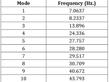
1.2 Model Analysis
Sample Modal Analysis is done to find out the Natural Frequency of the Top Roll Choke and to check if the natural frequency of the machine does not match the natural frequency of the Top Roll Choke to avoid resonance.
1) Material
Material Used – Fe 410
a. Young’s Modulus – 200GPa b. Poisson’s Ratio – 0.3
2) Element
a. Element Used – Solid 10 Node Tetrahedral (Solid 187)
b. Element Size – 30
3) Constraint
a. The bottom surfaces of the Top Roll Choke were constrained as shown in figure 1.1
Table 1.1Von Misses Contour Plot for Top Roll Chock
Mode Frequency (Hz.)
1 7.0637
2 8.2337
3 13.896
4 24.336
5 27.757
6 28.280
7 29.517
8 30.709
9 40.672
10 43.793
Also, the deformation for various Modes was plotted as shown in Figure 2.2
2. STRUCTURAL & MODEL ANALYSIS OF TOP BACK UP ROLL CHOCK
1) Material
Material Used – Fe 410
a. Young’s Modulus – 200GPa b. Poisson’s Ratio – 0.3
2) Element
a. Element Used – Solid 10 Node Tetrahedral (Solid 187)
b. Element Size – The appropriate Element Size was found out by using an Initial Element Edge Length to be 50 and then gradually reducing Element Size until the Stress remained constant even if the Element Size reduced. The Table 1.1 clearly indicates the above
Table 2.1 Element Size vs. Deformation
Sr. No. Element Size (mm) Deformation (mm)
1 50 0.197729
2 35 0.198522
3 30 0.198749
Therefore, Element Size 30 can be considered to be the ideal Element Size for the Following Analysis. Also, the Computer Available would require additional hardware to solve the number of equations for Element Size less than 30 is a constraint.
3) Forces
[image:2.595.75.250.421.484.2]© 2018, IRJET | Impact Factor value: 6.171 | ISO 9001:2008 Certified Journal | Page 425 b. The Top Roll Choke is constrained at the top of the
Rolling Mills by an adjustable Power Screw Mechanism.
c. The Reaction force is considered as the actual force acting on the choke and the bottom surfaces are considered to be constrained as shown in the figure 2.1
d. Therefore, the cylinder pressure is converted to force and applied on the particular area as shown in the figure 2.1
4) Constraint
[image:3.595.310.572.79.250.2]a) The bottom surfaces of the Top Roll Choke were constrained as shown in figure 2.1
Fig. 2.1 Meshing Diagram for Top Roll Chock
[image:3.595.36.295.288.463.2]Fig. 2.2 Total Deformation Contour Plot for Top Roll Chock
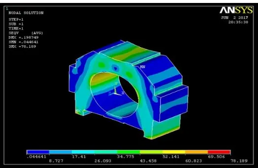
Fig. 2.3 Misses Contour Plot for Top Roll Chock
3. OPTIMIZATION OF TOP BACK UP ROLL CHOCK
The Top Roll Choke is optimized to a minimum size with Stress Constraints, Bearing Size Constraints. The Initial Stress Contour Plots Obtained in Chapter 2 was observed and studied. It was found out that parts of the roll choke had very little stress induced in them and could be removed.
The Following Iterations were carried out on the Roll Choke and a considerable weight reduction and thus cost savings was obtained.
[image:3.595.306.561.454.558.2]Iteration 1:-
Fig. 3.1 3D Model of 1st Iteration of Optimization of Top Back up Roll Chock
[image:3.595.40.551.479.731.2]© 2018, IRJET | Impact Factor value: 6.171 | ISO 9001:2008 Certified Journal | Page 426 Fig. 3.3 Von Misses Stress Contour of 1st Iteration of
[image:4.595.304.563.70.227.2]Optimization of Top Back up Roll Chock
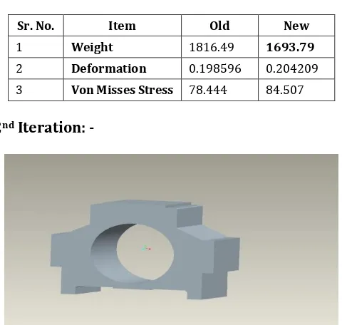
Table 3.1 Comparison of 1st Iteration and Existing Roll Chock
Sr. No. Item Old New
1 Weight 1816.49 1693.79
2 Deformation 0.198596 0.204209
3 Von Misses Stress 78.444 84.507
2nd Iteration: -
[image:4.595.34.287.77.224.2]Fig. 3.4 3D Model of 2nd Iteration of Optimization of Top Back up Roll Chock
[image:4.595.41.281.297.525.2]Fig. 3.5 Deformation Contour of 1st Iteration of Optimization of Top Back up Roll Chock
Fig. 3.6 Von Misses Stress Contour of 2nd Iteration of Optimization of Top Back up Roll Chock
Table 3.2 Comparison of 1st Iteration and 2nd Iteration Roll Chock
Sr. No. Item 1st Iteration 2nd Iteration
1 Weight 1693.79 1633.4
2 Deformation 0.204209 0.207976
3 Von Misses Stress 84.507 84.933
Thus a considerable weight saving is obtained as given below:-
Weight of Existing Roll Choke – 1816.49 kgs Weight of Optimized Roll Choke - 1633.4 kgs Cost Savings – Wt. Reduced x Rs. 50
183.495 x 50 Rs. 9154.5
Modal Analysis of Optimized Roll Choke
The Modes and their frequencies are given in Table 3.3:-
Mode Frequency (Hz.) Deformation (mm.)
1 7.5964 0.048917
2 7.6924 0.035799
3 15.710 0.051504
4 22.976 0.05069
5 24.667 0.060074
6 29.020 0.043498
7 29.047 0.071935
8 32.248 0.038319
9 37.795 0.043885
10 43.152 0.077078
4. CONCLUSIONS
[image:4.595.317.552.518.685.2] [image:4.595.37.289.573.705.2]© 2018, IRJET | Impact Factor value: 6.171 | ISO 9001:2008 Certified Journal | Page 427 chock of the machine experienced higher stresses at the
place where the holding of work role and back role occur. In the company there is failure of chock occurs during the process of operation so we designed the new chock for rolling machine by improving the all over safety factor. The new chocks have good life compare to failure one and from that chockcompany daily saving. Design Optimizations of Critical Component Roll Chocks in Cold Rolling Mill is really good project where designs of roll chock is totally new part.
REFERENCES
[1] G. P. Steven, “Multicriteria optimization that minimizes
maximum stress and maximizes stiffness”, Computers & Structures Volume 80, Issues 27-30 , November 2002, Pages 2433-2448.
[2] J. H. Rong, “An improved method for evolutionary
structural optimization against Buckling” Computers & Structures, Volume 79, Issue 3, January 2001, Pages 253-263.
[3] Kurt Maute, ‘an interactive method for the selection of
design criteria and the formulation of optimization problems in computer aided optimal design”, Computers Volume 82, Issue 1 , January 2004, Pages 71-79.
[4] Theodore G. ToRidis, “Computer analysis of rigid frames,
Computers”,Volume 1, Issues 1-2, August 1971, Pages 193-221.
[5] William Prager , “Conditions for structural optimality”,
Computers & Structures’,Volume 2, Issues 5-6, 1972, Pages 833-840.
[6] Rafael Febres, “Modeling of local buckling in tubular
steel frames subjected to cyclic Loading”, Computers & Structures, Volume 81, Issues 22-23, September 2003.
[7] A.I. Tseliko and V.V. Smirnov, M.H.T. Alford (1965),
Rolling Mills.
[8] William L.Roberts (1938), “Manufacturing engineering
and materials processing/2”,ColdRolling Of Steel.
[9] A.G.Davenport, “The application of statistical concept to
the wind loading of structure”, proc.Inst.Civil Engg. London 19(1961)449-472.
[10] Ginzburg Vladimir B.”High-Quality Steel Rolling Theory
and practice [M].Newyork”, USA,Marcel Deker Inc.(1993).
[11] Guide and Principal, Mechanical Department, VITS