© 2018, IRJET | Impact Factor value: 6.171 | ISO 9001:2008 Certified Journal | Page 1925
SCHOOL IN THE CLOUD
AsifAli S.Jamadar
1, Amey A.Chile
21M.Tech in Digital Electronics and communication systems 2Bachelor of Computer science
---***---Abstract -
The concept of E-learning is very broad. It was coined in late 90s as the technological enhanced learning mechanism through Internet. Now it captures a broad range of electronic media like Internet, Intranets, Extranets, satellite broadcast, audio, video tape, interactive TV and CD-ROM to make the learning procedure more flexible and user friendly. Because of the flexible nature of E-learning, it has got more demand among the people of our country and the demand is increasing day by day. As the demand is increasing, this is the time to standardize the whole e-learning system in a proper way and the time to increase the quality of existing standards. Though many standards are already there and has accepted by many academia, institutes and organizations, still there are some gaps and works are going on to make them more practicable and more systematic. It also analyses the importance of e-education system and recent market of e-learning procedure.Key Words: e-learning, Interactive TV, CD-ROM, Video tap, Extranet
1. INTRODUCTION
Every day new approaches are coming and bringing new prospects in education and trying to refine the system towards personalized self-learning. The benefits of E-learning are mainly the cost efficiency, accessibility and flexibility. Certainly education is the most important part of the human evolution and may be a crucial part of shaping the future of human beings.
The need for education is increasing constantly and the development and the improvement of the e-learning solutions is necessary. Also, the e-learning systems need to keep the pace with the technology, so the new direction is to use cloud computing.
Objective
In order to improve the quality of education in India. So we are proposing a cloud based e-learning system for the school
2. Overall Description:
2.1 Prospects
Learners can access information that is correct and up to date through the web, information databases or university.
Learners are able to meet in a virtual space with other members and practitioner experts to discuss issues, answer questions and even participate in simulations and management games without having to leave their office or home.
Learners benefit from learning when required, learners are able to access the right sort of training at the right time with the right people. Learners have access when the want it.
Learners have access to the same materials.
Learners regardless of where they are receive the same message and are able to engage other learners and practitioners globally.
2.2 Problem Statement
The current approach for e-learning is a manual which use the book and the teacher which is good, but that creates the difference between the studding approach for students. Implement of “Mid day meal” related skills are manually which can be cheated intentionally.
2.3 Minimum Hardware Requirement
RAM 256Mb
© 2018, IRJET | Impact Factor value: 6.171 | ISO 9001:2008 Certified Journal | Page 1926 2.4 Minimum Software Requirement
Java SDK
Eclipse with android plug-in Mysql
Ubuntu Desktop OS
3. Project Plan
Task Name Duration Start Finish
1 Scope 10 days Mon 7/1/13 Thu 7/11/13
1.1. Determine project scope 3 days Mon 7/1/13 Wed 7/3/13
1.2 Define preliminary resources 4 days Thu 7/4/13 Mon 7/8/13
1.3 Secure core resources 3 days Tue 7/9/13 Thu 7/11/13
1.4 Scope complete 10 days Mon 7/1/13 Thu 7/11/13
2 Analysis/Software Requirements 12 days Fri 7/12/13 Wed 7/24/13
2.1 Conduct needs analysis 2 days Fri 7/12/13 Sat 7/13/13
2.2 Draft preliminary software specifications 2 days Mon 7/15/13 Tue 7/16/13
2.3 Develop preliminary price for hardware 1 day Wed 7/17/13 Wed 7/17/13
2.4 Review software specifications/price with the
team 2 days Thu 7/18/13 Fri 7/19/13
2.5 Incorporate feedback on software
specifications 2 days Sat 7/20/13 Sun 7/21/13
2.6 Develop a completion timeline 1 day Mon 7/22/13 Mon 7/22/13
2.7 Obtain approvals to proceed (concept, timeline,
price) 1 day Tue 7/23/13 Tue 7/23/13
2.8 Secure required resources 1 day Wed 7/24/13 Wed 7/24/13
2.9 Analysis complete 12 days Fri 7/12/13 Wed 7/24/13
3 Design 16 days Thu 7/25/13 Fri 8/9/13
3.1 Review preliminary software specifications 4 days Thu 7/25/13 Sun 7/28/13
3.2 Develop functional specifications 2 days Wed 7/31/13 Thu 8/1/13
Requirement description Source
1 Main admin registers the school and upload the notification . Now school admin the register the tab and the upload standard wise video etc. School in the cloud
2 In client side, If the user is not authenticated or registered he has to register first. Then he can log in to the system. School in the cloud
3 In a school register enter the user name and detail about the school. when a tab register it contains the Mac address and detail about the student . School in the cloud
4 When user click on the application it verify the tab register it success go to the next, otherwise It is full. School in the cloud
© 2018, IRJET | Impact Factor value: 6.171 | ISO 9001:2008 Certified Journal | Page 1927 3.3 Develop prototype based on functional
specifications 2 days Fri 8/2/13 Sat 8/3/13
3.4 Review functional specifications 3 days Sun 8/4/13 Tue 8/6/13
3.5 Incorporate feedback into functional
specifications 2 days Wed 8/7/13 Thu 8/8/13
3.6 Obtain approval to proceed 1 day Fri 8/9/13 Fri 8/9/13
3.7 Design complete 16 days Thu 7/25/13 Fri 8/9/13
4 Development/Coding/Implementation 70 days Fri 8/2/13 Wed 10/30/13
4.1 Review functional specifications 6 days Fri 8/2/13 Wed 8/7/13
4.2 Identify modular/tiered design parameters 7 days Thu 8/8/13 Thu 8/15/13
4.3 Assign development staff 7 days Fri 8/16/13 Fri 8/23/13
4.4 Develop code 50 days Sat 8/24/13 Wed 10/30/13
4.5 Developer testing (primary debugging) 20 days Thu 10/31/13 Mon 11/25/13
4.4 Develop code 70 days Fri 8/2/13 Wed 10/30/13
5 Testing 45 days Thu 10/31/13 Fri 12/27/13
5.1 Unit Testing 18 days Thu 10/31/13 Fri 11/22/13
5.1.1 Review modular code 3 days Sat 11/23/13 Tue 11/26/13
5.1.2 Test component modules to product
specifications 4 days Wed 11/27/13 Mon 12/2/13
5.1.3 Identify anomalies to product specifications 3 days Tue 12/3/13 Thu 12/5/13
5.1.4 Modify the code 5 days Fri 12/6/13 Thu 12/12/13
5.1.5 Re-test modified code 3 days Fri 12/13/13 Tue 12/17/13
5.1.6 Unit testing complete 18 days Thu 10/31/13 Fri 11/22/13
5.2 Integration Testing 15 days Sat 11/23/13 Thu 12/12/13
5.2.1 Test module integration 2 days Sat 11/23/13 Mon 11/25/13
5.2.2 Identify anomalies to specifications 3 days Tue 11/26/13 Thu 11/28/13
5.2.3 Modify the code 7 days Fri 11/29/13 Mon 12/9/13
5.2.4 Re-test modified code 3 days Tue 12/10/13 Thu 12/12/13
5.2.5 Integration testing complete 15 days Sat 11/23/13 Thu 12/12/13
5.3 Functional Testing 12 days Fri 12/13/13 Fri 12/27/13
5.4 System Testing 12 days Fri 12/13/13 Fri 12/27/13
6 Documentation 8 days Mon 12/30/13 Tue 1/7/14
6.1 Develop Help specification 2 days Sat 12/28/13 Mon 12/30/13
6.2 Develop Help system 2 days Tue 12/31/13 Wed 1/1/14
6.3 Reviews Help documentation 2 days Thu 1/2/14 Fri 1/3/14
6.4 Incorporate Help documentation feedback 2 days Sat 1/4/14 Mon 1/6/14
6.5 Documentation complete 8 days Mon 12/30/13 Tue 1/7/14
© 2018, IRJET | Impact Factor value: 6.171 | ISO 9001:2008 Certified Journal | Page 1928
7.1 Determine final deployment strategy 1 day Wed 1/8/14 Wed 1/8/14
7.2 Develop deployment methodology 4 days Thu 1/9/14 Tue 1/14/14
7.3 Secure deployment resources 3 days Wed 1/15/14 Fri 1/17/14
7.4 Deploy software 2 days Sat 1/18/14 Mon 1/20/14
7.5 Deployment complete 10 days Wed 1/8/14 Mon 1/20/14
8 Software development complete 164 days Mon 7/1/13 Mon 1/20/14
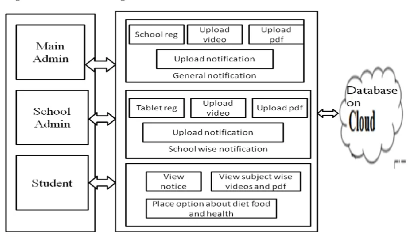
[image:4.595.142.429.235.466.2]3.1 Architecture:
Figure 1 Architecture
Now below figure shows the block diagram:
[image:4.595.77.486.508.745.2]© 2018, IRJET | Impact Factor value: 6.171 | ISO 9001:2008 Certified Journal | Page 1929
Figure 2 is a block diagram. In this diagram there are three modules Main Admin, School Admin & Student. Main admin contain school registration, it uploads video, notification & pdf. . School admin consists tablet registration it also contains standard wise videos & pdf. Student module view notification, videos & pdf.
4. Methodology AND Implementation
4.1 Use case Diagram
A use case is a functionality the users need from the system. A use case diagram depicts the relationships among the actors and use cases. It is usually used for requirements analysis. The components in a use case diagram include:
Actors: Actors are indicated as
Actors represent external entities of the system. These can be people or things that interact with the system that is being modeled. For example, if we are modeling an online store we have many actors that interact with the store functionality. The customer browses the catalog, chooses items to buy, and pays for those items. A stocker will look at the orders and package items for the customer. A billing system will charge the customer's credit card for the amount purchased.
Use Cases: Use case is indicatede by notation
Use cases are functional parts of the system. When we say what an actor does, that's a use case. The customer "browses the catalog", "choose items to buy", and "pays for the items". These are all use cases. Many actors can share use cases. If we find a use case that is not associated with any actor, this may be an unnecessary functionality.
Associations: Associations are indicated by the notation
Associations are shown between actors and use cases, by drawing a solid line between them. This only represents that an actor uses the use case.
There are also two kinds of relationships between use cases:
Includes: Include is represented as
© 2018, IRJET | Impact Factor value: 6.171 | ISO 9001:2008 Certified Journal | Page 1930 Extends:
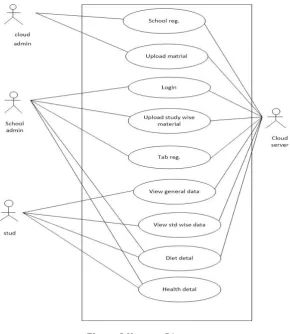
[image:6.595.153.444.150.485.2]An extension use case is an insertion to the base use case. For example, some stores may allow for different payment options like credit card, debit card, or cash on delivery. These specific functionalities are an extension of the general "pay for items." Extends relationship is represented by dashed arrows that point to the base functionality. Beside the arrow is <<extends>>
Figure 3 Use case Diagram
In above figure 3 shows the sequence diagram in which there is only one actor i.e user of the application and three use cases are present registration, login and user data.
4.2 Data Flow Diagram
Data Flow Diagram is re-present about System or a Sub System Process along with Data Flow, Data Storage and External Entity components. Context Diagram can design with any appropriate Notation and the Data Flow Diagram should design with following Pictograms. In practice, the Process, Data Flow, Data Store and External Entity should transform into Application Code, Screen, Data File and Application End User DFDs are constructed using four major components
1. External entries 2. Data stores 3. Processes and 4. Data flows
External entities representthe sourcee of data as input to the system. They are also the destination of system data. External entities can be called data stores outside the system. These are represented by squares. External entity is represented as
© 2018, IRJET | Impact Factor value: 6.171 | ISO 9001:2008 Certified Journal | Page 1931 Data stores are represented as
Processes represent activities in which data is manipulated by being stored or retrieved or transferred inn some way. In other words, we can say that process transforms the input data into output data. Circles stand for a process that converts data into information.
[image:7.595.66.541.202.440.2]Data flow represents the movement of data from one component to the other. An arrow (→) identifies data flow, i.e. data in motion. It is a pipeline through which information flows. Data flows are generally shown as one-way only. Data flows between external entities are shown as dotted lines (---›).
Figure 4 Data Flow Diagram for Student
Above figure 4 shows Data Flow Diagram in which the rectangle indicates the entities , the circle represents a process and arrows indicates the flow of information. In above figure we can see the flow of information in the system. First student access the school tab application then checking the tab verification.
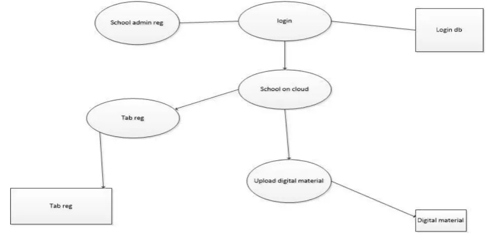
[image:7.595.53.535.514.751.2]© 2018, IRJET | Impact Factor value: 6.171 | ISO 9001:2008 Certified Journal | Page 1932 School Administrator.
[image:8.595.99.493.147.298.2]Above figure 5 shows Data Flow Diagram in which the rectangle indicates the entities , the circle represents a process and arrows indicates the flow of information. In above figure we can see the flow of information in the system. In this diagram first school admin login to the cloud database & after that it uploads video & other digital material.
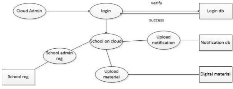
Figure 6 Diagram Main Administrator
Above figure 6 shows Data Flow Diagram in which the rectangle indicates the entities , the circle represents a process and arrows indicates the flow of information. In above figure we can see the flow of information in system. Cloud admin is the main admin it log on to the main database. & after that it uploads all material on that it also includes school registration.
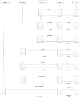
4.2 Sequence diagram
Sequence diagram is the most common kind of interaction diagram, which focuses on the message interchange between a number of lifelines.
Sequence diagram describes an interaction by focusing on the sequence of messages that are exchanged, along with their corresponding occurrence specifications on the lifelines.
The following nodes and edges are typically drawn in a UMLsequence diagram: lifeline, execution specification, message, combined fragment, interaction use, state invariant, continuation, destruction occurrence.
Lifeline: -Lifeline is a named element which represents an individual participant in the interaction. While parts and structural features may have multiplicity greater than 1, lifelines represent only one interacting entity.
Message: Message is a named element that defines one specific kind of communication between lifelines of an interaction. The message specifies not only the kind of communication, but also the sender and the receiver. The sender and receiver are normally two occurrence specifications (points at the ends of messages).
Combined fragment: Combined fragment is an interaction fragment which defines a combination (expression) of interaction fragments. A combined fragment is defined by an interaction operator and corresponding interaction operands. Through the use of combined fragments the user will be able to describe a number of traces in a compact and concise manner.
The combined fragment may have interaction constraints also called guards in UML 2.4.
Interaction use: Interaction use is an interaction fragment which allows to use (or call) other interaction. Large and complex sequence diagrams could be simplified with interaction uses. It is also common reusing some interaction between several other interactions.
Referenced interaction has formal gates. Interaction use provides a set of actual gates that must match the formal gates of the interaction.
Interaction use works as:
Copy the contents of the referred interaction to where this interaction needs to be used, Substitute formal parameters with arguments,
© 2018, IRJET | Impact Factor value: 6.171 | ISO 9001:2008 Certified Journal | Page 1933 The interaction use is shown as a combined fragment with operator ref.
State invariant: A state invariant is an interaction fragment which represents a runtime constraint on the participants of the interaction. It may be used to specify different kinds of constraints, such as values of attributes or variables, internal or external states, etc.
The constraint is evaluated immediately prior to the execution of the next occurrence specification such that all actions that are not explicitly modeled have been executed. If the constraint is true, the trace is a valid trace, otherwise the trace is an invalid trace.
State invariant is usually shown as a constraint in curly braces on the lifeline.
Occurrence: Destructionoccurrence is a message occurrence which represents the destruction of the instance described by the lifeline. It may result in the subsequent destruction of other objects that this object owns by composition. No other occurrence may appear below the destruction event on a given lifeline.
Complete UML name of the occurrence is a destruction occurrence specification. Until UML 2.4 it was called destruction event, and earlier - stop.
[image:9.595.142.450.311.686.2]The destruction of the instance is depicted with a cross in the form of an X at the bottom of a lifeline.
Figure 7 Sequence Diagram
© 2018, IRJET | Impact Factor value: 6.171 | ISO 9001:2008 Certified Journal | Page 1934
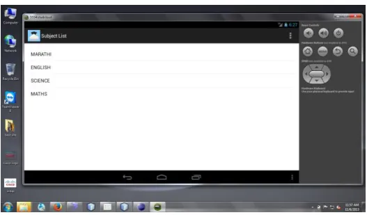
[image:10.595.171.428.241.377.2]Figure 8 Login window for students
Figure 9 After login class window for selecting class
Figure 10 window after class selection
[image:10.595.164.433.405.567.2] [image:10.595.166.430.594.748.2]© 2018, IRJET | Impact Factor value: 6.171 | ISO 9001:2008 Certified Journal | Page 1935 3. CONCLUSION
In this project, the sun tracking system is developed based on 89C51 microcontroller. The microcontroller 89C51 based circuit is used in this system with a minimum number of components and the use of stepper motors enables accurate tracking of the sun.It has been shown that the sun tracking systems can collect maximum energy than a fixed panel system collects and high efficiency is achieved through this tracker, it can be said that the proposed sun tracking system is a feasible method of maximizing the light energy received from sun. This is an efficient tracking system for solar energy collection.
REFERENCES
[1] Mayank Kumar Lokhande - Automatic Solar Tracking System
[2] Bipin Krishna &Kaustavsinha - Tracking of Sunfor Solar Panels and Real Time Monitoring Using Labview
[3] Reshmi Banerjee - Solar Tracking System
[4] Syed Arsalan - Sun Tracking System with Microcontroller 8051
[5] Tiberiu Tudorache&Liviu Kreindler - Design of a Solar Tracker System for PV Power Plants