© 2017, IRJET | Impact Factor value: 5.181
| Page 2179
Vehicle Tracking System for School Bus by Arduino
Supriya A Salunke
1, Vitthal B. Jagtap
2, Avinash D Harale
31
Solapur University, Department of Electronics
SKN Sinhgad College of Engineering, Pandharpur, Solapur,India.
2
Pune University, Department of Electronics
S.B Patil College of Engineering,Indapur, Pune, India.
3
Solapur University, Department of Electronics,
SKN Sinhgad College of Engineering, Pandharpur, Solapur,India.
Keywords: GPS and GPRS shield, Arduino uno board ,GPS Antenna, GPRS antenna
1. INTRODUCTION
The aim of this project is to design & develop a vehicle tracking system using GPRS which can be easily controlled by arduino uno. In this modern, fast moving and insecure world, it is became a basic necessity to be aware of one’s safety. The number of vehicles also increases on roads and highways. The proposed system is a GPS based real time vehicle tracking system, is used for security applications as well as any organization that maintains a large fleet and wants accurate real-time information about vehicle position.
For the implementation of this system use navigational technologies such as GPS, GPRS and database technologies.The system will be installing in a vehicle to allow the owner to track the vehicle’s location, this system will use GPS and GPRS module. Global Positioning System can determine the precise location of a vehicle.The GPS antenna present in the GPS receiver module receives the information from the GPS satellite in NMEA (National Marine Electronics Association) format and this information transmits to a server using GPRS module. GPRS provide TCP/IP connection with tracking server. Tracking server has
---Abstract: Global Positioning System (GPS) is becoming
widely used for tracking and monitoring vehicles. The system has been use for tracking vehicle in real time using GPRS (General Packet Radio Service) technology. The systems provide the possibility of tracking the location of vehicles at an affordable cost.
© 2017, IRJET | Impact Factor value: 5.181 | SO 9001:2008 Certified Journal
| Page 2180
received vehicle location information via network andstores this information in database. This information is available to authorized users of the system over the internet on map.
GPS is a satellite based navigation system, it is made up of 24 satellites, these satellites placed into the orbit. These satellites transmit coded information towards GPS receiver, this information use to identify vehicle locations on earth by measuring the distance from the satellites.
GPRS network is an "always on", private network for data. It uses the existing GSM network to transmit and receive TCP/IP based data to and from GPRS device/module. It support packet switched data services such as email and web browser. GPRS allows network operators to implement IP-based core architecture for data applications. The GPRS can transfer data at the maximum rate of 115.2 kbps. It is most suitable for a real-time tracking management system.
2. DESIGN METHOD:
The main objective of this project is to develop a vehicle location tracking system for tracking purpose. The signal received from satellite is sent to hardware devices for further processing and finally the signal is sent to the PC for displaying on the Google Map. This project is divided into two parts which are the tracking part and a displaying part. The tracking part is responsible for obtaining the user location while the control and displaying part is for displaying the detected location on the Google Map.
The hardware devices that are used in this project are the GPS and GPRS Shield Module and Arduino UNO Microcontroller. All of these hardware devices being programmed by using AT commands, and Arduino programming, php script. The software
that used to write the code is Arduino IDE. Besides that, a user interface was created by using a php script.
[image:2.595.325.543.131.306.2]A. Hardware Representation:
Figure 1: Hardware representation of vehicle tracking system using GPRS
B. GPS Receiver Module
Every single location in the entire globe can be specified in terms of geographical coordinates. The geographical coordinate is a system which specifies any given location on the earth surface as latitude and longitude. There are devices which can read the geographical coordinates of a place with the help of the signals received from a number of satellites orbiting the earth. The system of satellites which helps in the positioning of a place is called Global Positioning System (GPS). The devices which can read the geographical coordinates of a place with the help of at least four GPS satellites are called GPS Receiver or simply GPS module.
© 2017, IRJET | Impact Factor value: 5.181 | SO 9001:2008 Certified Journal
| Page 2181
or inputs can be taken from the boards or given to theboard.
C. GPS and GPRS shield assembly
[image:3.595.318.546.96.326.2]First assemble the GPRS+GPS shield with the antennas and the simcard installed, and configure your APN, login and password.. Also, set the URL with the IP address of your computer (external IP, not the LAN IP address) or your server's domain. The GPRS+GPS shield is connecting to the network and GPS module get position data and the 3G module that sends the HTTP request with the coordinates of the vehicle. It starts to send the HTTP request every few seconds with data of the position (latitude and longitude). It sends the GPS data through the Internet to the php. Script in your computer.Then we get the position of the device in Google Maps
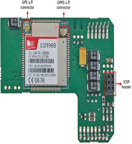
[image:3.595.70.295.397.641.2]Figure 2: Bottom view of GPS and GPRS module
Table 1: LED status
Status SIM908 behavior
Off SIM908 is not running
64ms On/ 800ms Off SIM908 not registered the network
64ms On/ 3000ms Off
SIM908 registered to the network
SIM908 registered to the network
PPP GPRS communication is established
The LED of the shield shows the status of the GPRS+GPS module. The Table 1.shows the meaning of the blink of the LED.
D. Control and displaying
php script is use to provide user interface for end user. To use the php script an server with php active is required. You can run the script in a PC.
E. Mapping
The Map form contains only a single Web browser. This form accepts the latitude and longitude and uses that data to display the position on the Google Maps. A query string is formed using round the latitude and longitude is passed to the web browser to navigate to the location which indicated by the latitude and longitude. To show the map with the marker we need url. The IP address or server domain is the same.
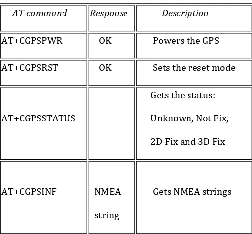
F. AT commands used for System
© 2017, IRJET | Impact Factor value: 5.181 | SO 9001:2008 Certified Journal
| Page 2182
Table 2: Get GPS data operation
AT command Response Description
AT+CGPSPWR OK Powers the GPS
AT+CGPSRST OK Sets the reset mode
AT+CGPSSTATUS
Gets the status:
Unknown, Not Fix,
2D Fix and 3D Fix
AT+CGPSINF
NMEA
string
Gets NMEA strings
3.Hardware Required:
A. GPS and GPRS Quadband module(SIM908)
SIM908 module is a complete Quad-Band GSM/GPRS module which combines GPS technology for satellite navigation.
General features
•Quad-Band 850/900/1800/1900MHz
•GPRS multi-slot class 10
•GPRS mobile station class B
•Low power consumption
•Dimensions: 30*30*3.2mm
•Weight:5.2g
Specification for GPS
•Receiver type
- 42-channel
- GPS L1 C/A code,
- High-performance STE engine
•Sensitivity
- Tracking: -160 dBm
- Cold starts : -143 dBm
•Time-To-First-Fix
- Cold starts: 30s (typ.)
- Hot starts: 1s (typ.)
•Power consumption (GSM engine in idle mode)
- Acquisition 77mA
- Tracking 76mA
B. GPRS+GPS shield:
Figure 3: Top view of GPS and GPRS module
[image:4.595.310.553.392.573.2]© 2017, IRJET | Impact Factor value: 5.181 | SO 9001:2008 Certified Journal
| Page 2183
[image:5.595.39.263.105.255.2]C. Antennas Connection With Module:
Figure 4: External antenna connection with shield
External GPS Antenna specifications: It includes a SMA-Female to UFL pigtail.
Frecuency: GPS 1575.42 MHz Impedance: 50 Ohms
Polarization: RHCP
Gain: 26dB at 3V, 28dB at 5V VSWR: <1.2:1
Supply Voltage 2.7V - 5.5V Current: 15mA - 25mA Power (max.): 125mW Connector: SMA Male
Size: 41mm x 34mm x 13.7mm
Operating temperature -40°Cto +85°C
External GPRS antenna specification
The new quadband antenna offers a gain of 2.14 dBi. It includes a RPSMA to uFL pigtail.
Frequency: 4G/LTE (791-862/1710-2690 MHz), 3G (UMTS 2.1 GHz), GSM Quadband (850-900-1800-1900 MHz) WIFI / BLUETOOTH (2.4 GHz) Impedance: 50 Ohms
Polarization: horizontal Gain: 2.14dBi
VSWR: <2:1
Power handling: 25W Connector: RPSMA Male Size: 114mm x 9mm
Operating temperature: -40°Cto +85°C
D. Arduino uno Board:
Figure 5: Arduino Uno board
The Uno is a microcontroller board based on the ATmega328P. It has 14 digital input/output pins (of which 6 can be used as PWM outputs), 6 analog inputs, a 16 MHz quartz crystal, a USB connection, a power jack, an ICSP header and a reset button. It contains everything needed to support the microcontroller; simply connect it to a computer with a USB cable or power it with a AC-to-DC adapter or battery to get started.
4. Results
[image:5.595.340.587.575.740.2]© 2017, IRJET | Impact Factor value: 5.181 | SO 9001:2008 Certified Journal
| Page 2184
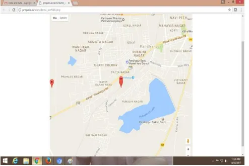
[image:6.595.47.277.563.745.2]Figure 7: SKN Korti to Pandharpur bus location positions
Figure 8: SKN Korti to Pandharpur bus location positions
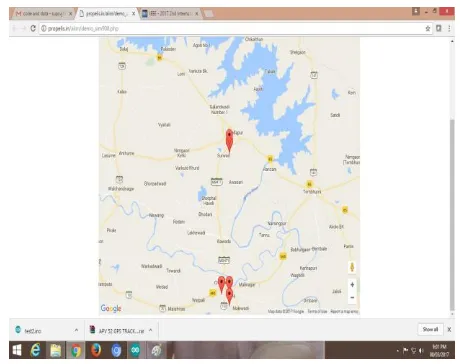
Figure 9: Indapur to Akluj bus location positions
Above figure shows Different bus locations for experimental purpose, like
1) SKN korti Pandharpur Bus location
2) Indapur to Akluj Bus locations
5. Conclusion:
The goal of this project was to be to create a Vehicle tracking system to tracked bus location. System gave longitude and latitude for bus location.
The implementation of this control structure on tracked location using GPS and GPRS, it shows a good performance in very difficult terrain, even with the limitation of having GPS sensitivity.
References
[1] Saurabh S chakole, Vivek R. Kapur, and Y.A.Suryawanshi, “ARM Hardware Platform and Vehicular Monitoring and Tracking”, International Conference on Communication Systems and Network
Technologies, pp.757-761, 2013.
[2] Ali Ziya Alkar, Member, IEEE, and Mehmet Atif Karaca , “ An Internet-Based Interactive Embedded Data-Acquisition System for Real-Time Applications”,IEEE Transactions on instrumentation and measurement, vol. 58, no. 3, pp 522- 529, March 2009.
[3] Chih-Ching LI, Chh-Chen Wu, H. S. Liu, and M. Y. Tseng, “A Real Time GPRS Surveillance System using the Embedded System”, pp.1228-1234, 2003.
[4] Ming Lu a, Wu Chen b, Xuesong Shen , Hoi-Ching Lam and Jianye Liu c ,“Positioning and tracking construction vehicles in highly dense urban areas and Building construction sites”, pp.647–656, 2007.
[5] Xing Jianping, Zhang Jun, Cheng Hebin, Li Changqing and Shi Xiaohui,“ GPS Real Time Vehicle Alarm Monitoring System Base on GPRS/CSD using The Embedded System”, pp.1155-1158, 2006
© 2017, IRJET | Impact Factor value: 5.181 | SO 9001:2008 Certified Journal
| Page 2185
Research in Computer and Communication Technology,
Vol 3, pp.1329-1333, October 2014.
[7] Lee, S., Tewolde, G and Kwon, J., "Design and implementation of vehicle tracking System using GPS/GSM/GPRS technology and smartphone application." Internet of Things (WF-IoT), IEEE, 2014.
[8] Fabio Valente, Giammarco Zacheo, Pierfrancesco Losito and Pietro Camarda, “A Telecommunications Framework for Real-Time Monitoring of Dangerous Goods Transport”, pp.13-18, 2009.