Multiuser/Multitasking Operating System
os
SYSTEMS GUIDE
COPYRIGHT
Copyright © 1987 Digital Research Inc. All rights reserved. No part of this publication may be reproduced, transmitted, transcribed, stored in a retrieval system, or translated into any language or computer language, in any form or by any means, electronic, mechanical, magnetic, optical, chemical, manual, or otherwise, without the prior written permission of Digital Research Inc., 60 Garden Court, P.O. Box DRI, Monterey, California 93942.
DISCLAIMER
DIGITAL RESEARCH INC. MAKES NO REPRESENTATIONS OR WARRANTIES WITH RESPECT TO THE CONTENTS HEREOF AND SPECIFICALLY DISCLAIMS ANY IMPLIED WARRANTIES OF MERCHANTABILITY OR FITNESS FOR ANY PARTICULAR PURPOSE. Further, Digital Research Inc. reserves the right to revise this publication and to make changes from time to time in the content hereof without obligation of Digital Research Inc. to notify any person of such revision or changes.
NOTICE TO USER
TRADEMARKS
Digital Research and its logo, CP/M, and CP/M-86 are registered trademarks of Digital Research Inc. Cardfile, Concurrent, Concurrent DOS XM, Concurrent DOS 386, DR EDIX, CBASIC, and Personal BASIC are trademarks of Digital Research Inc. "We Make Computers Work." is a service mark of Digital Research Inc.
All rights reserved.
The following are registered trademarks of the listed companies.
Registered Trademark
IBM Intel Lotus Microsoft Quadram
Company
International Business Machines Intel Corporation
Lotus Development Corp. Microsoft Corporation Quadram Corporation
The following are trademarks of the listed companies.
Trademark
1-2-3
Ashton-Tate MS-DOS Symphony
Company
Lotus Development Corp. Ashton-Tate Corporation Microsoft Corporation Lotus Development Corp.
The Concurrent DOS System Guide was printed in the United Kingdom.
FOREWORD
The Concurrent™ DOS System Guide is intended for the original equipment manufacturer (OEM) and system programmer responsible for implementing Concurrent DOS XM or Concurrent DOS 386 (hereinafter cited as Concurrent) on a disk-based microcomputer that uses an Intel(R) 8086, 8088, 80186, 80286 or 80386 microprocessor with a real-time clock. Concurrent is a multitasking, real-time operating system that can be implemented in single or multiple user configurations.
Manual Organization
This manual documents the internal, hardware-dependent structures of Concurrent and is arranged as follows:
...
...
...
...
...
...
...
...
...
...
...
...
...
...
...
Section 1 introduces the major features of the system and describes its levels of interface and the responsibilities of the primary modules.
Section 2 describes how to generate a Concurrent system with the GENSYS utility.
Section 3 provides an overview of the physical interface to Concurrent. the Extended Input/Output System (XIOS).
Section 4 describes XIOS support for character devices .
Section 5 describes XI OS support for disk devices .
Section 6 describes Concurrent's support for expanded memory .
Section 7 describes the special functions required for DOS program support .
Section 8 details the responsibilities of an interrupt-driven XI OS tick routine .
Section 9 contains suggestions for debugging the XIOS .
Section 10 describes an example bootstrap procedure .
Section 11 offers guidelines for writing hardware-specific utilities for OEM distribution.
Section 12 outlines the changes required in Concurrent's end-user documentation when an OEM makes certain modifications to the operating system.
Appendix A describes removable media support .
Appendix B offers considerations for implementing graphics capabilities .
Example XIOS
Many sections of this manual refer to the example XIOS. Digital Research(R) provides an example XI OS for the IBM PC, XT, AT and PS2 family of personal computers. The example XIOS contains all the major features of a multi-user, hard-disk, paged-memory Concurrent implementation including support of DOS applications via serial terminals on Concurrent DOS 386 and character windowing support for a video-mapped display. Source code is included on the Concurrent distribution disks. We strongly suggest that you assemble the source files according to the instructions in Section 2 and that you refer often to the assembly listing while reading this manual.
Concurrent Documentation
The presentation of information in this manual assumes that you are familiar with the following documents:
*
*
*
*
The Concurrent DOS User's Guide (cited as the User's Guide) describes the various features of Concurrent's user interface.
The Concurrent DOS Reference Guide (cited as the User's Reference Guide) is a user reference manual that provides a detailed description of every Concurrent command.
The Concurrent DOS Programmer's Guide (cited as the Programmer's Guide) describes the system's application programmer interface.
The Assembler plus Tools Guide manuals document the RASM-86™ relocating assembler, the LlNK-86™ linkage editor, the LlB-86™ software librarian, XREF-86™ the cross referencer and the SID-86 symbolic instruction debugger. This manual is cited as the Programmer's Reference Guide.
Digital Research supports the user and software interfaces described in the User's Guide, User's Reference Guide, and Programmer's Guide; Digital Research does not support any additions or modifications made to Concurrent by an OEM or distributor. The OEM or distributor must also support the hardware interface (XI OS) for a particular hardware environment.
Terminology
Contents
1 System Overview
1.1 Concurrent Organization ... 1-2 1.2 Memory Layout ... 1-3 1.3 Supervisor ... 1-4 1.4 Real-time Monitor ... 1-5 1.5 Memory Management Module ... 1-7 1.6 Character 1/0 Module ... 1-7 1.7 Basic Disk Operating System ... 1-8 1.8 Extended 1/0 System ... 1-9 1.9 XIOS Reentrancy ... 1-9 1.10 The System Data Area ... 1-10 1.11 Resident System Processes ... 1-17 1.12 DOS Device Driver Support ... 1-17
2 Building the System
2.1 Required Files ... 2-1 2.2 Invoking GENSYS ... 2-2 2.3 The GENSYS Main Menu ... 2-3 2.4 System Parameters Menu ... 2-5 2.5 Memory Allocation Menu ... 2-8 2.6 Disk Buffering Menu ... 2-9 2.7 OSLABEL Menu ... 2-9 2.8 RSP List Menu ... 2-10 2.9 PHASE Option ... 2-10 2.10 GENSYS Option ... 2-10 2.11 GENSYS Input Files ... 2-11
3 XIOS Overview
3.1 XIOS Header ... 3-1 3.2 INIT Entry Point ... 3-7 3.3 XIOS ENTRY ... 3-8 3.4 Polled Devices ... 3-12 3.5 Interrupt Devices ... 3-13 3.6 Numeric Data Processor Exception Handler ... 3-14 3.7 PCIAT ROS Interrupt Support ... 3-17 3.8 XI OS System Calls ... 3-18
4 Character Devices
Contents
5 Disk Devices
5.1 Disk 1/0 Functions ... 5-1 5.2 1/0 Parameter Block ... 5-9 5.3 Multisector Operations on Skewed Disks ... 5-12 5.4 Disk Parameter Header ... 5-15 5.5 Disk Parameter Block ... 5-17 5.5.1 Disk Parameter Block Worksheet ... 5-22 5.5.2 Disk Parameter Control List Worksheet ... 5-25 5.6 Buffer and Hash Control Blocks ... 5-26 5.6.1 Buffer Control Blocks Format ... 5-26 5.6.2 Hash Control Format ... 5-27 5.7 Memory Disk Applications ... 5-28 5.8 Multiple Media Support ... 5-28 5.9 SYSDAYTA Space A"ocation ... 5-29
6 Expanded Memory Support
6.1 Memory Paging Environments ... 6-1 6.1.1 Generic Environment ... 6-2 6.1.2 EMM Environment ... 6-2 6.2 Expanded Memory Data Structure ... 6-3 6.2.1 Memory Window Descriptor ... 6-3 6.2.2 Memory Page Allocation Descriptor ... 6-3 6.3 Expanded Memory Function Calls ... 6-5
7 PC/AT ROS Support
7.1 XIOS Functions for ROS Video Support ... 7-2 7.2 XIOS Functions for ROS Disk Support ... 7-3 7.3 XIOS Functions for ROS Keyboard Support ... 7-4 7.4 XIOS Functions for ROS System Configuration Support ... 7-6
8 XIOS Tick Interrupt Routine
9 Debugging the XIOS
10 Bootstrap Adaption
10.1 The Bootstrap Loader on Floppy Disks ... 10-1 10.2 The Bootstrap Loader on Hard Disks ... 10-1 10.3 Other Bootsrap Methods ... 10-1 10.4 Organization of CCPM.SYS ... 10-4
11 OEM Disk Utilities
11.1 Direct-Disk Access Precautions ... 11-1
Contents
Appendix A Removable Media ... A-1 Appendix B Graphics Implementation ... B-1 Appendix C Concurrent DOS 386 Considerations ... C-1 Index ... Index-1
Tables
1-1 Supervisor System Calls ... 1-5 1-2 Real-Time Monitor System Calls ... 1-6 1-3 Memory Management System Calls ... 1-7 1-4 Character 1/0 System Calls ... 1-8 1-5 BDOS System Calls ... 1-8 1-6 SYSDAT Data Field ... 1-12 2-1 System Parameters Menu Options ... 2-5 3-1 XIOS Header Fields ... 3-2 3-2 XIOS Register Usage ... 3-8 3-3 XIOS Functions ... 3-9 4-1 Console Control Blocks ... 4-3 4-2 XIOS Window Functions ... 4-10 4-3 List Control Block Fields ... 4-18 5-1 Disk 1/0 Extended Error Codes ... 5-1 5-2 10PB Data Fields ... 5-10 5-3 Disk Parameter Fields ... 5-16 5-4 Standard Disk Parameter Block Fields ... 5-17 5-5 Extended Disk Parameter Block Fields ... 5-20 5-6 BSH and BlM Values ... 5-22 5-7 EXM Values ... 5-23 5-8 Directory Entries per Block Size ... 5-23 5-9 AlO, Al1 Values ... 5-24 5-10 PSM and PRM Values ... 5-25 6-1 Memory Window Descriptor Fields ... 6-4 6-2 Memory Page Allocation Descriptor Fields ... 6-5 7-1 10 INT13 Status Byte Vales ... 7-4 7-2 Keyboard Shift Status Bit Map ... 7-5 7-3 DOS Equipment Status Bit Map ... 7-6 C-1 V386 PTR Structure Definition ... C-1
Figures
Contents
4-1 The CCB Table ... 4-2 4-2 Console Control Block Format ... 4-3 4-3 CCBs for Two Physical Consoles ... 4-4 4-4 The LCB Table ... 4-17 4-5 List Control Block ... 4-18 4-6 Auxiliary Control Block Table ... 4-19 4-7 Auxiliary Control Block ... 4-19 4-8 Stack Contents for 10 DEVIO call ... 4-23 5-1 DMA Address Table for Multisector Operations ... 5-12 5-2 Disk Parameter Header ... 5-15 5-3 Standard Disk Parameter Block Format ... 5-17 5-4 Extended Disk Parameter Block Format ... 5-19 5-5 Buffer Control Block Fields ... 5-26 5-6 Hash Control Block Fields ... 5-27 6-1 Generic EnvironmentMemory Paging Interfaces ... 6-2 6-2 EMM Environment Memory Paging ... 6-3 6-3 Memory Window Descriptor ... 6-3 6-4 Memory Page A"ocation Descriptor ... 6-4 10-1 Section Descriptors - CCPM.SYS Header Record ... 10-2 C-1 V386 PTR Structure ... C-1
Listings
Section 1
SYSTEM OVERVIEW
Concurrent is a multitasking, real-time operating system. It can be configured to support one or more user terminals. Each user terminal can run multiple tasks simultaneously on virtual consoles. Concurrent's extended features include intercommunication and synchronization of independently running processes and expanded memory support that allows the system to address up to eight megabytes of memory. Concurrent is designed to be implemented in a large variety of hardware environments and as such, you can customize it to fit that hardware environment and/or user's needs.
Concurrent also supports many IBM Personal Computer Disk Operating System (PC DOS) and MS-DOS™ programs. The standard disk media type (DOS) is fully compatible with PC DOS and MS-DOS disks. In this manual, the term DOS refers to both PC-DOS and MS-DOS. In addition, for compatibility with previous versions of Concurrent, the XI OS may support CP/M media and a special utility supplied with Concurrent allows files to be moved easily to and from the CP/M media.
Concurrent consists of three levels of interface: the user interface, the logically invariant software interface, and the hardware interface. The user interface distributed by Digital Research is a Resident System Process (RSP) called the Terminal Message Process (TMP). The TMP accepts commands from the user and either performs the function itself or passes the command to the operating system via the Command Line Interpreter (CLI). The Command Line Interpreter in the operating system kernel either invokes an RSP or loads a disk file to perform the command.
The logically invariant interface to the operating system consists of the system calls described in the Programmer's Guide. The logically invariant interface also connects transient and resident processes with the hardware interface.
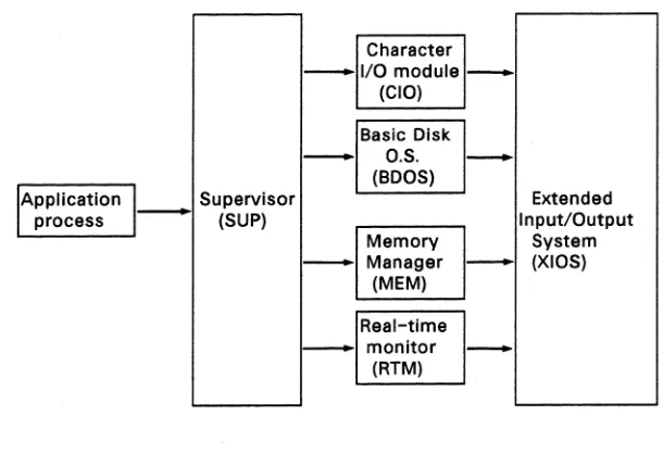
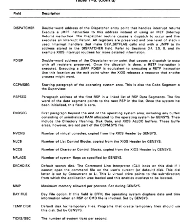
The physical interface, or XIOS (extended I/O system), communicates directly with the particular hardware environment. The XIOS is composed of a set of functions which are called by processes that need physical I/O. Sections 3 through 7 describe these functions. Figure 1-1 shows the relationships between the three interfaces.
System Overview
' - - - '
Supervisor
- (SUP)
-Concurent DOS 86 System Guide
Character I/O module
(CIO)
Basic Disk O.S. (BOOS)
Memory Manager
(MEM)
Real-time monitor
(RTM)
--
Extended Input/OutputSystem - (XIOS)
-Figure 1-1. Concurrent Interfaces
1.1 CONCURRENT ORGANIZATION
Concurrent is composed of seven basic code modules. The Real-time Monitor (RTM) handles process-related functions, including dispatching, creation, and termination, as well as the Input/Output system state logic. The Memory module (MEM) manages memory and handles the Memory Allocate and Memory Free system calls. The Character I/O module (CIO) handles all console, list, and auxiliary device functions. The Basic Disk Operating System (BOOS) manages the file system. These four modules communicate with the Supervisor (SUP), the Extended Input/Output System (XIOS) and the Dos function support module (PCMOOE).
The SUP and PCMOOE module manage the interaction between transient processes, such as user programs, and the system modules. All function calls go through a software interrupt interface to SUP or PCMOOE.
[image:13.468.64.369.75.284.2]Concurent DOS 86 System Guide Concurrent Organization
All operating system code modules, including the SUP and XIOS, share a data segment called the System Data Area (SYSDAT). The beginning of SYSDAT is the SYSDAT DATA, a well-defined structure containing public data used by all system code modules. Following this fixed portion are local data areas that belong to specific code modules. The XIOS area is the last of these code module areas. Following the XIOS Area are Table Areas, used for the Process Descriptors, Queue Descriptors, System Flag Tables, and other operating system tables. These tables vary in size depending on the options you choose when you use GENSYS during system generation. See Section 2, "Building the System," for a description of how to use GENSYS.
The Resident System Processes (RSPs) occupy the area in memory immediately before the SYSDAT module. The RSPs you select at system generation time become an integral part of the operating system. For more information on RSPs, see Section 1.11, "Resident System Processes," and the Programmer's Guide.
Concurrent loads all transient programs into the Transient Program Area (TPA). The TPA for a given implementation of Concurrent is determined at system generation time.
1.2 MEMORY LAYOUT
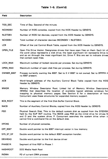
The Concurrent DOS operating system area can exist anywhere in memory except over the interrupt vector area. To provide complete DOS support, neither the system nor the TPA should be located below paragraph 60H. You define the exact location of Concurrent during system generation. The GENSYS program determines the memory locations of the system modules that make up Concurrent based upon system generation parameters and the size of the modules. In the case of a system that runs from Read only memory (ROM) then the image is built in the usual way except that the location of Concurrent is given as the start of ROM. The image is then blown into one or more ROMs as required. At "power up" the data part of the ROM image is first copied by a small routine to its location in Random access memory (RAM).
The XIOS is written as a small model (8080 model in previous versions).
The CCPM.SYS file is built by GENSYS from some or all of the following files depending on the requirement.
CDOS.CON XIOS.CON CLOCK.RSP -PIN.RSP PCTMP.RSP -INIT.CON NET.CON
Concurrent Kernel (SUP,PCMODE,MEM,RTM,CIO,BDOS) Input/output system
Clock process
Physical input process Terminal process Initialisation code Network code
Memory Layout
(TOp of Memory)
TPA
Dynamic Buffers Table Area
XIOS Data SYSDAT Data Stat i c Buffers
XIOS Code RSP Code and Data
DR Net Code and Data (optional)
COOS Code Interrupt Vectors (Start of memory)
End of
as
AreaWithin 64k
60:0
00:0
Concurent DOS 86 System Guide
(End of File)
INIT Code and Data
CCPM.SYS Data Group
CCPM.SYS Code Group
O:BO .CMD Header
0:00
(Start of Fi le)
Figure 1-2. Memory Layout and File Structure
1.3 SUPERVISOR and PCMODE
The Concurrent Supervisor (SUP) and (PCMODE) manage the interface between system and transient processes and the invariant operating system.
Concurent DOS 86 System Guide Supervisor and PCmode
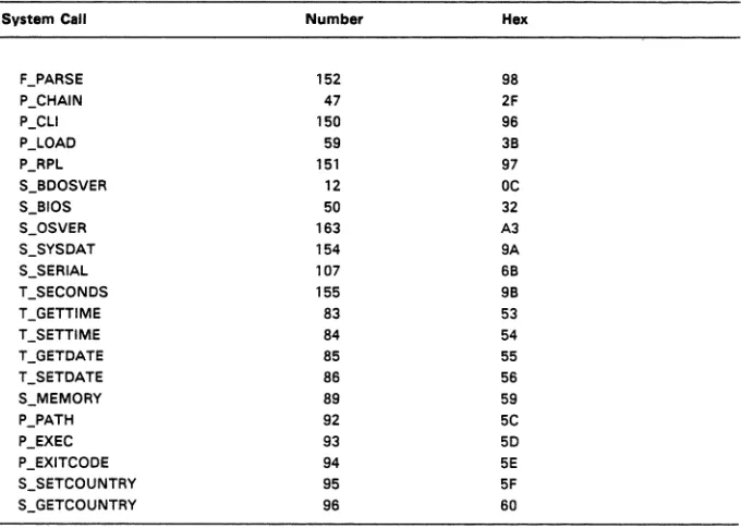
Table 1-1. Supervisor System Calls
System Call Number Hex
F_PARSE 152 98
P_CHAIN 47 2F
P_CLI 150 96
P_LOAO 59 38
P_RPL 151 97
S_800SVER 12 DC
S_810S 50 32
S_OSVER 163 A3
S_SYSOAT 154 9A
S_SERIAL 107 68
T_SECONOS 155 98
T_GETTIME 83 53
T_SETTIME 84 54
T_GETOATE 85 55
T_SETOATE 86 56
S_MEMORY 89 59
P_PATH 92 5C
P_EXEC 93 50
P_EXITCOOE 94 5E
S_SETCOUNTRY 95 5F
S_GETCOUNTRY 96 60
1.4 REAL-TIME MONITOR
The Real-time Monitor (RTM) is Concurrent's multitasking kernel. It handles process dispatching, queue and flag management, device polling, system timing tasks, and the logical interrupt system. The primary function of the RTM is to transfer the CPU resource from one process to another, a task accomplished by the RTM dispatcher. At every dispatch operation, the dispatcher stops the currently running process and stores its state in the Process Descriptor (PO) and User Data Area (UDA) associated with that process. The dispatcher then selects the highest-priority process in the ready state and restores it to execution, using the data in its PO and UDA. A process is in the ready state if it is waiting for the CPU resource only. The new process continues to execute until it needs an unavailable resource, a resource needed by another process becomes available, or an external event, such as an interrupt, occurs. At this time the RTM performs another dispatch operation, allowing another process to run.
[image:16.468.82.422.85.328.2]Real-Time Monitor Concurent DOS 86 System Guide
When the XIOS needs to wait for an interrupt, it issues a DEV_WAITFLAG system call on a logical interrupt device. When the appropriate interrupt actually occurs, the XIOS calls the DEV_SETFLAG system call to put process in the ready state. The interrupt routine then performs a Far Jump to the RTM dispatcher, which reschedules the interrupted process, and all other ready processes that are not yet on the Ready List. At this point, the dispatcher brings the process with the highest priority into execution.
The system clock typically generates interrupts, or clock ticks, 50 or 60 times per second. This allows Concurrent to effect process time slicing. Since the operating system waits for the tick flag, the XIOS tick interrupt routine must execute a Concurrent DEV _SETFLAG system call at each tick (see Section 8, "XIOS Tick Interrupt Routine") and then perform a Far Jump to the RTM dispatcher. Processes with equal priority are scheduled for the CPU resource in round-robin fashion. If no process is ready to use the CPU, Concurrent remains in the dispatcher until an interrupt occurs or a polling process is ready to run.
The RTM also handles queue management. System queues are composed of a Queue Descriptor, which contains the queue name and other parameters, and a Queue Buffer, which can contain a specified number of fixed-length messages. Processes read these messages from the queue on a FIFO basis. A process can write to or read from a queue either conditionally or unconditionally.
When a process attempts a conditional read from an empty queue, or a conditional write to a full one, the RTM returns an error code to the calling process. A process that attempts an unconditional read or write in these situations is suspended until the requested operation can be accomplished.
Table
1-2
lists the RTM system calls. See the Programmer's Guide for more complete information about RTM functions.Table 1-2. Real-time Monitor System Calls
System Call Number Hex System Call Number Hex
DEV_SETFLAG 133 85 P_TERM 143 8F
DEV_WAITFLAG 132 84 P_TERMCPM 0 00
DEV_POLL 131 83 a_CREAT 138 8A
P_A80RT 157 9D a_CWRITE 140 8C
P_CREATE 144 90 a_DELETE 136 88
P_DELAY 141 8D a_MAKE 134 86
P_DISPATCH 142 8E a_OPEN 135 87
P_PDADR 156 9C a_READ 137 89
P_PRIORITY 145 91 a_wRITE 139 88
Concurent DOS 86 System Guide Memory Management Module
1.5 MEMORY MANAGEMENT MODULE
The Memory Management module (MEM) handles all memory functions for both conventional (non-banked) and expanded memory (banked). Expanded memory is defined as memory (up to eight megabytes) that can be enabled or disabled at a specific address on command by the XI OS. Memory that cannot be changed in this way is conventional memory. The MEM module uses linked lists to allocate and deallocate the memory and to allow the dispatcher to ensure that a process always has its memory in context when it runs. The XIOS creates or trims these lists at initialisation time depending on the hardware requirement.
Table
1-3.
Memory Management System CallsSystem Call Number Hex System Call Number HEX
M_ALLOC 128/129 80181 MC_ALLOC
M_FREE 130 82 MC_ABSALLOC 56 38
MC_ABSMAX 54 36 MC]REE 57 39
MC_ALLFREE 58 3A MC_MAX 53 35
Note: The MC_ prefix denotes system calls supported for compatibility with CP/M-86 and MP/M-86™. These calls internally execute the M_ALLOC and M]REE system calls. See the Programmer's Guide for descriptions of the memory management system calls.
1.6 CHARACTER I/O MODULE
The Character Input/Output (CIO) module handles all console, list, and auxiliary device I/O and provides an interface to the XIOS and the PIN (Physical Input) process. The PIN process handles keyboard input for each user terminal.
The XIOS associates device control blocks with each of the devices managed by the CIO. The Console Control Block (CCB), List Control Block (LCB), and Auxiliary Control Block (ACB) data structures are described in Sections 4.1, 4.4, and 4.5, respectively.
Character I/O Module Concurent DOS 86 System Guide
Table 1-4. Character 1/0 System Calls
Svstem Can Number Hex Svstem Cen Number Hex
C_ASSIGN 149 95 C_STAT 11 OB
C_ATTACH 146 92 C_WRITE 02 02
C_CATTACH 162 A2 C_WRITEBLK 111 6F
C_OELIMIT 110 6E C_WRITESTR 09 09
C_OETACH 147 93 L_ATTACH 158 9E
C_GET 153 99 L_CATTACH 161 Al
C_MOOE 109 60 L_OETACH 159 9F
C_RAWIO 06 06 L_GET 164 A4
C_REAO 01 01 L_SET 160 AO
C_REAOSTR 10 OA L_WRITE 05 05
C_SET 148 94 L_WRITEBLK 112 70
The Programmer's Guide presents an overview of the CIO and describes the CIO system calls in detail. The XIOS character device functions are described in Section
4.
1.7 BASIC DISK OPERATING SYSTEM
Table 1-5 lists the Concurrent Basic Operating System (BOOS) system calls. These calls handle all file system functions. The Programmer's Guide describes the BOOS in detail.
Table 1-5. BOOS System Calls
Svstem Can Number Hex Svstem Can Number Hex
ORV_ACCESS 38 26 F_MAKE 22 16
ORV _ALLOCVEC 27 lB F_MULTISEC 44 2C
DRV_OPB 31 IF F_OPEN 15 OF
DRV]LUSH 48 30 F_PASSWD 106 6A
DRV_GET 25 19 F_READ 20 14
DRV_GETLABEL 101 65 F_READRAND 33 21
DRV_LOGINVEC 24 18 F_RANDREC 36 24
DRV_RESET 37 25 F_RENAME 23 17
ORV_ROVEC 29 lD F_SFIRST 17 11
DRV_SET 14 OE F51ZE 35 23
Concurent DOS 86 System Guide Basic Disk Operating Systems
Table 1-5. (Cont'd)
System Call Number Hex System Call Number Hex
DRV_SETRO 28 lE F_TIMEOATE 102 66
DRV_SPACE 46 2E F_TRUNCATE 99 63
F_ATTRIB 30 lE F_UNLOCK 43 2B
F_CLOSE 16 10 F_USERNUM 32 20
F_OELETE 19 13 F_WRITE 21 15
F_DMASEG 51 33 F _ WRITERANO 34 22
F_OMAGET 52 34 F _ WRITEXFCB 103 67
F_DMAOFF 26 lA F_WRITEZF 40 28
F_ERRMOOE 45 20 T_GET 105 69
F_LOCK 42 2A T_SET 104 68
DEV_LOCK 90 SA OEV_UNLOCK 91 5B
F_DOS 113 71
1.8 EXTENDED I/O SYSTEM
The Extended Input/Output System (XIOS) manages Concurrent's interface to the hardware. By modifying the XIOS, you can run Concurrent in a large variety of hardware environments.
The XIOS recognizes two basic types of 1/0 devices: character devices and disk devices. Character devices are devices that handle one character at a time, while disk devices handle random blocked 1/0 using data blocks sized from one physical disk sector to the number of physical sectors in 16K bytes. Devices that vary from these two models must be implemented within the XIOS so that they appear to the other operating system modules as standard Concurrent 1/0 devices.
Sections 4, "Character Devices" through 7, "PC Mode Character 1/0" contain detailed descriptions of the XIOS functions.
1.9 XI OS REENTRANCY
Concurrent allows multiple processes to use certain XIOS functions simultaneously and guarantees that only one process can use a particular physical device at any given time. However, some XI OS functions handle more than one physical device, and thus their interfaces must be reentrant. An example of this is the 10_CONOUT (2) function to which the calling process passes the virtual console number. There can be several processes using the function, each writing a character to a different virtual console or character device; however, only one process is actually sending a character to a given device at any time.
XIOS Reentrancy Concurent DOS 86 System Guide
The IO_SELDSK (9), IO_READ (10), IO_WRITE(11), and IO_FLUSH (12) file functions are assumed to be protected by the BOOS or the DEV_LOCK function so that only one process may access them at a time. Because of this protection, none of these XIOS functions need to be reentrant.
1.10 THE SYSTEM DATA AREA
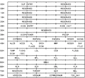
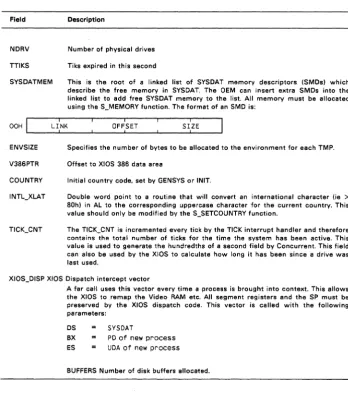
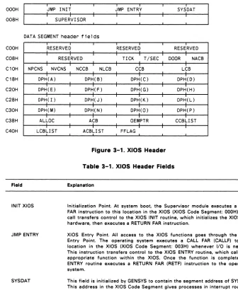
The System Data Area (SYSDAT) is the data segment for all modules of Concurrent. As shown in Figure 1-3, the SYSDAT segment is composed of four main areas. The first part is the fixed-format portion, containing global data used by all modules. This is the SYSDAT DATA. It contains system variables, including values set by GENSYS and pointers to the various system tables. The Internal Data portion contains fields of data that belong to individual operating system modules. The XIOS data begins at the end of this second area of SYSDAT. The fourth portion of SYSDAT is the System Table Area. The System Table Area is generated and initialized by the GENSYS system generation utility.
Offset System
Table Area nnnnh
XIOS Data
OcOOh
Internal Data
0100h
SYSDAT Data
OOOOh
Figure 1-3. SYSDAT
Concurent DOS 86 System Guide The System Data Area
OOH
08H
10H
18H
20H
28H
30H
38H
40H
48H
50H
58H
60H
68H
70H
78H
SUP ENTRY RESERVED
RESERVED RESERVED
RESERVED RESERVED
RESERVED RESERVED
RESERVED RESERVED
XIOS ENTRY XIOS INIT
RESERVED
DISPATCHER PDISP
CCPMSEG RSPSEG ENDSEG RESER NVCNS
NLCB NCCB N - SRCH MMP RESER DAY
FLAGS DISK FILE
TEMP TICKS LUL CCB FLAGS
DISK /SEC
MDUL MFL PUL QUL
QMAU
RLR DLR DRL PLR
RESERVED THRDRT QLR MAL
VERSION VERNUM CCPMVERNUM TOO_DAY
[image:22.469.75.364.52.315.2]The System Data Area Concurent DOS 86 System Guide
SOH
SSH
90H
9SH
AOH
ASH
BOH
BSH
COH
CSH
DOH
DSH
EOH
ESH
FOH
FSH
Field
TOO TOO TOO NeON NLST Nero LeB
-
HR _MIN _SEC DEV DEV DEVOPEN_FILE LOCK_ OPEN_ OWNER
-
ACBMAX MAX SOS7
RESERVED
MWDR BCB..,ROOT NACB PSD RESER XPCNS
OFF.,SOS7 SYS_S7_0F
RESERVED DEVHEAD PHASE1R
HASHROOT I NOMA NDRV TTIKS SYSDATMEM
ENVSIZE RESERVED
RESERVED
V3S6_PTR COUNTRY INTL_XLAT
TICK_CNT XIOS_DISP
BUFFERS RESERVED
RESERVED
RESERVED
RESERVED
[image:23.468.45.381.33.538.2]RESERVED
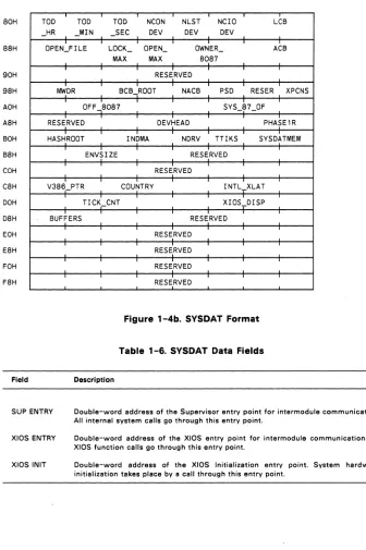
Figure 1-4b. SYSDAT Format
Table
1-6.
SYSDAT Data FieldsDescription
SUP ENTRY Double-word address of the Supervisor entry point for intermodule communication. All internal system calls go through this entry point.
XIOS ENTRY
XIOS INIT
Double-word address of the XIOS entry point for intermodule communication. All XIOS function calls go through this entry point.
[image:23.468.45.338.42.311.2]Concurent DOS 86 System Guide The System Data Area
Field
DISPATCHER
PDISP
CCPMSEG
RSPSEG
ENDSEG
NVCNS NLCB NCCB NFLAGS SRCHDISK
MMP DAY FILE
TEMP DISK
TICKS/SEC
Table 1-6. (Cont'd)
Description
Double-word address of the Dispatcher entry point that handles interrupt returns. Execute a JMPF instruction to this address instead of using an IRET (Interrupt Return) instruction. The Dispatcher routine causes a dispatch to occur and then executes an Interrupt Return. All registers are preserved and one level of stack is used. Interrupt handlers that make DEV_SETFLAG calls end with a JMPF to the address stored in the DISPATCHER field. Refer to Sections 3.4, 3.5, 8, and the example XIOS interrupt routines for more detailed information.
Double-word address of the Dispatcher entry point that causes a dispatch to occur with all registers preserved. Once the dispatch is done, a RETF instruction is executed. Executing a JMPF PDISP is equivalent to executing a RETF instruction. Use this location as the exit point when the XI OS releases a resource that another process might want.
Starting paragraph of the operating system area. This is also the Code Segment of the Supervisor.
Paragraph address of the first RSP in a linked list of RSP Data Segments. The first word of the data segment points to the next RSP in the list. Once the system has been initialized, this field is zero.
First paragraph beyond the end of the operating system area, including any buffers consisting of uninitialized RAM allocated to the operating system by GENSYS. These include the Directory Hashing, Disk Data, and XIOS ALLOC buffers. These buffer areas, however, are not part of the CCPM.SYS file.
Number of virtual consoles, copied from the XIOS Header by GENSYS. Number of List Control Blocks, copied from the XI OS Header by GENSYS. Number of Character Control Blocks, copied from the XIOS Header by GENSYS. Number of system flags as specified by GENSYS.
Default search disk. The Command Line Interpreter (CLI) looks on this disk if it cannot open the command file on the user's current (or default) disk. This disk letter is set by Concurrent to L:. This L: virtual drive points to the sub-directory from which the application was loaded and this enables overlays to be located. Maximum memory allowed per process. Set during GENSYS.
Day File option. If this field is OFFH, the operating system displays date and time information when an RSP or CMD file is invoked. Set by GENSYS.
Default disk for temporary files. Programs that create temporary files should use this disk. Set by GENSYS.
[image:24.474.54.423.61.514.2]The System Data Area Concurent DOS 86 System Guide
Field
LUL
Table 1-6. (Cont'd)
Description
Locked Unused List. This is the link list root of unused Lock List Items. Concurrent uses Lock List Items to manage open files and records locked for executing processes. Lock List Items are also used to store information on subdirectory paths and files opened in unlocked mode.
The number of Lock List Items is determined by the value you set for NOPENFILES during GENSYS. See Section 2.4 for a description of related system parameters and the Programmer's Guide for information about Concurrent's security mechanisms for file access.
CCB Address of the Character Control Block Table, copied from the XI OS Header by GENSYS.
FLAGS Address of the Flag Table.
MDUL Memory Descriptor Unused List. Link list root of unused Memory Descriptors. MFL Memory Free List. Link list root of free memory partitions.
PUL Process Unused List. Link list root of unused Process Descriptors (PDs). QUL Queue Unused List. Link list root of unused Queue Descriptors. QMAU Queue buffer Memory Allocation Unit.
RLR Ready List Root. Linked list of PDs that are ready to run.
DLR Delay List Root. Linked list of PDs that are delaying for a specified number of system ticks.
DRL Dispatcher Ready List. Temporary holding place for PDs that are in the ready state. PLR Poll List Root. Linked list of PDs that are polling on devices.
THRDRT Thread List Root. Linked list of all current PDs in the system. The list is threaded though the THREAD field of the PO instead of the LINK field. See the Programmer's Guide for a description of the Process Descriptor's fields.
QLR Queue List Root. Linked list of all System Queue Descriptors.
MAL Memory Allocation List. Linked list of active Memory Allocation Units (MAUs). A MAU is created from one or more memory partitions.
VERSION Address, relative to CCPMSEG, of ASCII version string.
VERNUM Concurrent version number (returned by the S_BDOSVER system call). CCPMVERNUM Concurrent version number (system call 163, S_OSVER).
TOO_DAY Time of Day. Number of days since 1 Jan, 1978. TOD_HR Time of Day. Hour of the day.
Concurent DOS 86 System Guide The System Data Area
Table 1-6. (Cont'd)
Field Description
TOO_SEC Time of Day. Second of the minute.
NCONDEV Number of XIOS consoles, copied from the XIOS Header by GENSYS. NLSTDEV Number of XIOS list devices, copied from the XI OS Header by GENSYS. NCIODEV Total number of character devices (NCONDEV + NLSTDEV).
LCB Offset of the List Control Block Table, copied from the XIOS Header by GENSYS. OPEN_FILE Open File Drive Vector. Designates drives that have open files on them. Each bit of
the word value represents a disk drive; the least significant bit represents Drive A.
and so on through the most significant bit. Drive P. Bits are set to indicate drives that contain open files.
LOCK_MAX Maximum number of locked records per process. Set during GENSYS. OPEN_MAX Maximum number of open disk files per process. Set during GENSYS.
OWNER_8087 Process currently owning the 8087. Set to 0 if 8087 is not owned. Set to OFFFFH if no 8087 present.
ACB Word-length address of the Auxiliary Control Block Table copied from the XIOS Header by GENSYS.
MWDR Memory Window Descriptor Root. Linked list of Memory Window Descriptors (MWDs) that describes the location of available logical address windows for mapping to physical memory pages. See Section 6 for a description of how Concurrent uses these structures for expanded memory support.
BCB_ROOT This is the segment of the first Disk Buffer Control Block.
NACB Number of Auxiliary Control Blocks, copied from the XIOS Header by GENSYS. PSD Physical Search Disk. This is the default system disk as copied from the SYSDISK
field by the SUP INIT routine. The BOOS uses PSD as the initial drive for drives N and 0 and the system drive, P. Concurrent searches the system drive when it cannot find a command file on the default disk.
XPCNS Number of physical consoles.
OFF _8087 Double word pointer to the 8087 interrupt vector in low memory. SYS_87 _OF Double word pointer to the default 8087 exception handler. DEVHEAD Double word pointer to the first device driver
PHASE1 R Segment of first RSP in Phase 1 HASH ROOT DOS Media Hash Root
[image:26.473.73.422.38.553.2]The System Data Area Concurent DOS 86 System Guide
Field
NDRV TTIKS SYSDATMEM
Table 1-6. (Cont'd)
Description
Number of physical drives Tiks expired in this second
This is the root of a linked list of SYSDAT memory descriptors (SMDs) which describe the free memory in SYSDAT. The OEM can insert extra SMDs into the linked list to add free SYSDAT memory to the list. All memory must be allocated using the S_MEMORY function. The format of an SMD is:
OOH LI _____
L~I:_NK
____~
____O_F_F~:S_E_T
____~
____ S_I:LZ_E __~
ENVSIZEV386PTR COUNTRY
Specifies the number of bytes to be allocated to the environment for each TMP. Offset to XI OS 386 data area
Initial country code. set by GENSYS or INIT.
Double word point to a routine that will convert an international character (ie >
80h) in AL to the corresponding uppercase character for the current country. This value should only be modified by the S_SETCOUNTRY function.
The TICK_CNT is incremented every tick by the TICK interrupt handler and therefore contains the total number of ticks for the time the system has been active. This value is used to generate the hundredths of a second field by Concurrent. This field can also be used by the XIOS to calculate how long it has been since a drive was last used.
XIOS_DISP XIOS Dispatch intercept vector
A far call uses this vector every time a process is brought into context. This allows the XIOS to remap the Video RAM etc. All segment registers and the SP must be preserved by the XIOS dispatch code. This vector is called with the following parameters:
OS SYSOAT
BX PO of new process
ES UOA of new process
[image:27.471.47.396.66.464.2]Concurent DOS 86 System Guide Resident System Processes
1.11 RESIDENT SYSTEM PROCESSES
Resident System Processes (RSPs) are an integral part of the operating system. At system generation, the GENSYS RSP List menu lets you select which RSPs to include in the operating system. GENSYS then places all selected RSPs in a contiguous area of RAM starting at the end of the BOOS code. RSPs are permanently resident within the Operating System Area and do not have to be loaded from disk when they are needed. Concurrent itself uses three RSPs, PIN, TMP and CLOCK.
Concurrent automatically allocates a Process Descriptor (PO) and User Data Area (UDA) for a transient program, but each RSP is responsible for the allocation and initialization of its own PO, UDA, and Queue Descriptor (QD). Concurrent uses the PO and QD structures declared within an RSP directly if they fall within 64K of the SYSDAT segment address. If the RPS's PO and QD are outside of 64K, they are copied to a PO or QD allocated from the Process Unused List or the Queue Unused List. In either case, the PO and QD of the RSP lie within 64K of the beginning of the SYSDAT Segment. This allows RSPs to occupy more area than remains in the 64K SYSDAT segment.
See the descriptions of the process system calls and the queue management calls in the Programmer's Guide for definitions of the UDA and QD structures, respectively. The Programmer's Guide also contains details on creating and using RSPs.
1.12 DOS DEVICE DRIVER SUPPORT
Concurrent supports DOS installable drivers for device, fixed disks, and expanded memory.
The Init module checks for the presence of the ASCII file CCONFIG.SYS on the root of the current disk. If it finds CCONFIG.SYS, it reads the file and executes the following commands (if present).
DEVICE = f i 1 espec FIXED-DEVICE = fi lespec EMM = f i 1 espec
EEMM = f i 1 espec
COUNTRY = nnn LASTDRIVE = d ENV-S I ZE = nnnn BREAK = ON BUFFERS = nnn
- Loads a dev i ce dr i ver
- Loads a fixed disk device driver - Loads an expanded memory dr i ver
- Loads an expanded memory driver and the SCEPTER.CMD program.
- nnn is the requ i red count ry code - d is the last drive (A - Z)
- environment size in bytes (128-32,750) - or OFF (set keyboard break)
- defines the number of additional disk buffers
Resident System Processes Concurent DOS 86 System Guide
Section 2
BUILDING THE SYSTEM
The GENSYS utility allows you to build the Concurrent system image file, CCPM.SYS. This program combines an assembled XIOS and the system modules provided on the distribution disks. GENSYS also displays menus that allow you to define
*
certain hardware-dependent variables*
the amount of memory to reserve for system data structures*
the Resident System Processes to be included in CCPM.SYS*
other system parameters.This section describes how to use the GENSYS utility.
Note: You can generate a Concurrent system by running GENSYS under an
existing DOS Plus or Concurrent system.
See Section 9, "Debugging the XIOS:' for debugging suggestions.
2.1 REQUIRED FILES
GENSYS requires that the following files be present on the current disk:
* INIT.CON
*
COOS.CON*
XIOS.CON*
PIN.RSP*
TMP.RSP*
CLOCK.RSP*
FLUSH.RSP-- Concurrent Initialisation module -- Concurrent Kernel module -- Input/Output System module -- Physical keyboard input process -- Terminal Message Process -- CLOCK process
-- DOS terminal flush process (CDOS 386 only)
If GENSYS cannot find these files, it displays the following error message:
Can't f; nd these modu 1 es: <F I LESPEC> ... {<F I LESPEC>}
where FILESPEC is the name of the missing file.
An extension of RSP denotes a Resident System Process file. Concurrent requires the PIN, TMP, and CLOCK RSPs to run.
All of the modules listed except XIOS.CON are provided on the distribution disk. An unassembled XIOS is provided as a model. You should write the XI OS as small model program (separate code and data) originating the data at location OCOOH.
Note: For compatibility the 8080 model is still supported by GENSYS. If the 8080
Required Files Concurent DOS 86 System Guide
Use the RASM-86 relocatable assembler and the LlNK-86 linker according to the following guidelines:
*
Include CSEG and OSEG directives in every module to instruct the assembler to place the code and data in the appropriate group. If the segments are named and grouped then this will allow alignment of data items on word boundaries.*
The first module named in the LlNK-86 command line that contains code or data should be the module that defines the XIOS Header. This module should define the data starting at "ORG OCOOH" and immediately define the header data fields. It should also define the code starting at "ORG 0" and immediately define the required code segment fields.See section 3.1 for a description of the XIOS Header.
*
Use the LlNK-86 "DATA[ORIGIN[Oll" option to prevent the linker from automatically adding a base page.2.2 INVOKING GENSVS
GENSVS has the following command syntax:
GENSYS [-xm] [-386] [<input file] [>output file]
Both the input and output files are optional. GENSVS reads the input file to set parameters. See section 2.11 below for instructions on creating input files for GENSYS. Specify an output file to record the screen displays produced by GENSYS.
Before displaying the Main Menu, GENSVS checks the current drive for the files necessary to construct the operating system image. If a module is not found, GENSVS displays the message shown above and terminates operation. Otherwise, the Main Menu is displayed.
Concurent DOS 86 System Guide The GENSYS Main Menu
2.3 THE GENSYS MAIN MENU
Figure 2-1 depicts the GENSYS Main Menu. Default values for an option are contained in brackets .
••• Concurrent DOS 6.0 GENSYS Main Menu ••• hel p GENSYS Hel p
verbose [Y] More Verbose GENSYS Messages
destdrive [C:] CCPM.SYS Output To (Destination) Drive deletesys [N] Delete (instead of rename) old CCPM.SYS fi le sysparams
memory diskbuffers oslabel
Di spl ay /Change System Parameters
D i sp 1 ay /Change Memory All ocat i on Part it ions Display/Change Disk Buffer Allocation Display/Change Operating System Label drnet [N] Attaching Networking
rsps Display/Change RSP 1 ist
phase D i sp 1 ay /Change Phase 1 Process 1 i st
gensys I'm finished changing things, go GEN a SYStem Changes?
Figure 2-1. GENSYS Main Menu
The Main Menu items set general parameters (verbose, destdrive, drnet and deletesys), provide access to the submenus (sysparams, memory, diskbuffers, oslabel, phase, and rsps) and initiate system building (gensys).
The general parameters are defined as follows:
verbose
destdrive
deletesys
drnet
GENSYS displays submenu options either with or without an explanation. Set verbose to Y to get the explanations; set it to N for the minimum explanations.
GENSYS writes the new CCPM.SYS file on the drive designated by destdrive. If you do not specify a destination drive, GENSYS uses the current drive.
GENSYS either deletes or renames the existing CCPM.SYS file when it creates a new one. Set deletsys to Y to delete the old file; set it to N to rename it. GENSYS renames the previous copy of CCPM.SYS as CCPM.OLD.
GENSYS either attaches the NETSYS.CON module to the built CCPM.SYS or not.
The GENSYS Main Menu
sysparams (2.4)
Command response FCB compatibility mode Maximum memory per process
Concurent DOS 86 System Guide
Maximum number of open files.per process Maximum number of locked records per process System's starting paragraph
Total number of open file and locked record entries Number of Process Descriptors and Queue Control Blocks Total size of queue buffer
Number of system flags
memory (2.5) Memory partitions and their addresses
diskbuffers (2.6)
Maximum number of buffers per process Use of directory buffer hashing
oslabel (2.7) Virtual console sign-on message.
rsps (2.8) Resident System Processes (RSPs) to be included or excluded
phase (2.9) Specify phase order of the initial process starting.
The gensys option builds the system image file. If an input file is used to specify system parameters and the GENSYS command is not the last line in the input file, GENSYS uses its interactive mode to prompt you for any additional changes. See Section 2.11, "GENSYS Input Files," for more information.
Changes? is the Main Menu prompt. Terminate your entries by typing a carriage return at the Changes? prompt.
To change the three Main Menu options, enter the option name followed by the new value. You can use the following abbreviations:
v for verbose des for destdrive del for deletesys dr for drnet
To access one or more of the submenus, enter the submenu name or names at the Changes? prompt. You can change options and list more than one submenu on a single line. For example, the following command:
Changes? v=y, des=c: ,sysparams, os label, rsps ,gensys
*
sets the verbose mode*
sets the destination drive for the new system image file*
displays the sysparams, oslabel, and rsps submenus*
builds the new system imageConcurent DOS 86 System Guide The GENSYS Main Menu
Type HELP at the prompt to display an explanation of Main Menu features and how to proceed.
The following sections describe the submenu parameters and how to construct an input file.
2.4 SYSTEM PARAMETERS MENU
The System Parameters Menu is shown in Figure 2-2. Type SYSPARAMS in response to the Main Menu Change? prompt to select the System Parameters menu. Note that all numeric values are in hexadecimal notation. The values in brackets are the default values. Table 2-1 describes the System Parameters menu items.
Display/Change System Parameters Menu sysdrive [L:] System Drive tmpdrive [A:] Temporary Fi Ie Drive
cmdlogging [N] Command Day/Fi Ie Logging at Console compatmode [Y] CP/M FCB Compatibility Mode
envsize country memmax sysmem open max lockmax osstart nhandles nopenfiles nlocks npdescs nqcbs qbufsize nflags Changes?
Parameter
SYSDRIVE
TMPDRIVE
[#512] Command Envi ronment Si ze
[#44] Init ial Country Code
[4000] Maximum Memory per Process (paragraphs)
[ 100] Extra System Data Page Memory (Bytes)
[20] Open F i I es per Process Max i mum
[20] Locked Records per Process Max i mum
[ 1008] Starting Paragraph of Operating System
[ 80] Number of Fi Ie Handle Entries
[ 40] Number of Open F i I es
[ 40] Number of Locked Record Ent r i es
[ 14] Number of Process Descriptors
[20] Number of Queue Cont ro I Blocks
[ 400] Queue Buffer Total Size in bytes
[20] Number of System Flags
Figure 2-2. GENSYS System Parameters Menu
Table 2-1. System Parameters Menu Options
Description
This is the default drive searched by Concurrent when it cannot locate a file in the current directory on a P _CLI call. This value is recorded in the SRCHDISK field of the SYSDAT DATA structure. The default value is L: which is the virtual drive used to load the current application.
System Parameters Menu Concurent DOS 86 System Guide
Parameter
CMDLOGGING
COMPATMODE
ENVSIZE
COUNTRY
MEMMAX
OPENMAX
LOCKMAX
OSSTART
NHANDLES
Table 2-1. (Cant'd)
Description
Set to Y to display the time and the name of the file executed after each user command entry. The information is displayed on a single line in the following form:
hh : mm : ss f i 1 ename
A Y value also enters OFFH in the DAY FILE field of the SYSDAT DATA structure.
Set to Y to have Concurrent use the CP/M compatibility attributes recorded with each file; specify N to have Concurrent ignore the file's compatibility attributes. See the Programmer's Guide for a description of the compatibility attributes.
Set the default size of the environment to be given to all loaded applications. This value becomes the value in the ENV_SIZE field of the SYSDAT DATA. Set the initial country code. 44 is the code for the UK, 01 is the code for USA. This value is placed in the COUNTRY field of the SYSDAT DATA.
Set to the maximum paragraphs of memory you want allocated to each process. Although processes make their own memory allocations, this value represents an upper limit on how much memory each process can obtain. This value becomes the MMP value in the SYSDAT DATA structure.
Set to the maximum number of open files you allow per process. The range for this value is 0 to 255 (OFFH). The value must be less than or equal to the total open files and locked records for the system (see the NOPENFILES parameter description below). This value becomes the OPEN_MAX value in SYSDAT DATA.
Set to the maximum number of locked records you allow per process. The range is 0 to 255 (OFFH), and the value must be less than or equal to the total open files and locked records for the system (see NOPENFILES parameter description below). This value is used for LOCK_MAX in SYSDAT DATA. Set to the operating system's starting paragraph address. Code execution starts here with register CS set to this value, IP set to 0, and the Data Segment Register set to the SYSDAT segment address. This value is used for the CCPMSEG field in SYSDAT DATA.
[image:35.469.42.399.28.548.2]Concurent DOS 86 System Guide System Parameters Menu
Parameter
NOPENFILES
NLOCKS
NPDESCS
NQCBS
QBUFSIZE
NFLAGS
Table 2-1. (Cont'd)
Description
This value is the total number of files that may be open in the system. Each entry in this table occupies 2 bytes of SYSDAT DATA.
This entry sets the total number of allowed lock list and HDS items in the system. An HDS item is required for each sub- directory currently open on the system. A lock list item is required for each record currently locked on the system. The size of an item in this list is 10 bytes.
Set to the number of Process Descriptors. A Process Descriptor is required for each process in the system. every RSP that extends 64K past the beginning of SYSDAT, and the first time a process changes directories. A Process Descriptor is 30H bytes long. Note that processes created by other processes (referred to as child processes) require their own Process Descriptor. See the description of the PUL (Process Unused List) field in Section 1.10, "SYSDAT DATA," for related information.
Set to the maximum number of Queue Control Blocks. Queues creeted by transient programs and those RSPs outside the 64K of the SYSDAT segment address each require a Queue Control Block. The Physical Keyboard Input (PIN) RSP also uses one Queue Control Block for each Virtual Input Queue (VINQ) it creates. The PIN RSP requires a VINQ for each of the system's virtual consoles.
Determine a value for NQCBS by adding the number of virtual consoles in your system to the number of Queue Control Blocks you allocate for transient processes.
Set to the size, in bytes, of the Queue Buffer Area. Allocate enough space for queues created by transient programs, RSPs outside the SYSDAT segment addess, and VINQs (see NQCBS, above). The amount of buffer area required for each queue is the message length times the number of messages. The PIN RSP creates a VINQ of SOH bytes for each virtual console in a system. Determine the size of the Queue Buffer Area by adding SOH bytes for each virtual console to the amount of space required for transient programs' queue messages.
The maximum size of the Queue Buffer Area is OFFFFH.
Set to the maximum number of flags required by the system. This value is used for NFLAGS in SYSDAT DATA.
Memory Allocation Menu Concurent DOS 86 System Guide
2.5 MEMORY ALLOCATION MENU
Figure 2-3 depicts the use of the Memory Allocation Menu. Initially, the menu indicates the current memory partitions. Add and delete partitions by entering ADD and DELETE commands at the Changes? prompt. The session shown in Figure 2-3
deletes all current partitions and creates 16K (4000H) partitions from address 2400:0 to 4000:0 and 32K (BOOOH) partitions from 4000:0 to 6000:0.
Addresses Part it ions
# Start Last Si ze Qty 1. 400h 6000h 400h 17h
Di spl ay/Change Memory All ocat ion Part it ions add ADD memory partition(s) delete DELETE memory partition(s)
Changes? delete=· add=2400,4000,400 add=4000, 6000, 800 Addresses Partitions
# Start Last S; ze Qty 1. 2400h 4000h 400h 7h 2. 4000h 6000h eOOh 4h
Display/Change Memory Allocation Partitions add ADD memory partition(s) delete DELETE memory partition(s) Changes? <cr>
Figure 2-3. GENSYS Memory Allocation Sample Session
The add and delete partition specifications consist of:
* the beginning address of the memory region to be partitioned
*
the ending address of the memory region to be partitioned*
the size, in paragraphs, of the partitionsAll values must be in hexadecimal notation and separated by commas. The Start and Last values on the menu are paragraph addresses; divide the absolute address by 10H to specify the paragraph address. Partition sizes are also in paragraphs; divide the actual partition size by 10H to enter the size parameter.
Use an asterisk to delete all memory partitions.
The memory partitions cannot overlap each other or the operating system area. GENSYS checks and trims memory partitions that overlap the operating system, but does not trim partitions that overlap each other. GENSYS displays an error message when the partitions overlap or are incorrectly sized and does not allow you to exit the Memory Allocation Menu if the memory partition list is not valid.
Concurent DOS 86 System Guide Memory Allocation Menu
Concurrent allocates partitions in whole; a single partition is never divided among unrelated programs. If a memory request requires a memory segment that is larger than the available partitions, Concurrent concatenates adjoining partitions to form a single contiguous area of memory. The MEM module algorithm that determines the best fit for a given memory allocation request takes into account the number of partitions requested and the amount of partition space left over.
To determine the appropriate partitions, consider the applications to be run. Where small programs are run frequently and large programs only occasionally, divide memory into small partitions. This model simulates dynamic memory management and is very memory-efficient as long as memory does not become too fragmented. (When memory is too fragmented, the MEM module cannot find enough contiguous memory space for programs with large memory requirements even when enough memory is available.) Use the large partition model when large programs are run most frequently or programs are run serially. A good general-purpose compromise is to divide memory into 4K to 16K partitions.
2.6 DISK BUFFERING MENU
Figure 2-4 shows a sample Disk Buffering Menu session. This allows the default number of disk buffers required on the system to be set. INIT will extend the number of buffers if the CCONFIG.SYS file requests more buffers than have already been set up. The XIOS can optionally decide to set the default buffers itself. If this is the case a flag in the XIOS header is set to indicate to GENSYS that no default buffers are required. The minimum number of buffers required for the system to "come up" is 3. The number of directory entries to be hashed is also set by this menu. Again this may be allocated by the XIOS and it flags in the XIOS header if no hash entries are to be allocated by GENSYS.
Make changes by entering responses to the prompts displayed by GENSYS.
*** Disk Buffering Information ***
nobuffers [3] The number of default disk buffers to be allocated hashent r i es [200] The number of hashed directory ent r i es
buffersize [200] Maximum physical sector size clustersize [0800] Maximum cluster size
Figure 2-4. Disk Buffering Menu Session
2.7 OSLABEL MENU
Figure 2-5 shows the OS LABEL Menu. Select this menu to write a message for display on all virtual consoles when the system is loaded.
Display/Change Operating System Label Current message is:
<null>
Add 1 ines to message. Terminate by entering only RETURN:
OSLABEL Menu Concurent DOS 86 System Guide
Enter the message using spaces to format the display. Terminate each line with a carriage return. To end the message, enter a carriage return at the beginning of the line. Use the $ character to terminate the display message but continue with comments. Note that where the XIOS prints its own sign-on message, the XIOS message appears before the message specified in the GENSYS OSLABEL Menu.
2.8 RSP LIST MENU
Figure 2-6 shows a session with the GENSYS RSP (Resident System Process) List Menu. GENSYS gets the initial list of RSPs by scanning the current drive's directory. All files with an extension of RSP are listed. The following session excludes MY.RSP and COM.RSP:
RSPs to be included are: PIN.RSP
COM.RSP
TMP.RSP
Display/Change RSP List include
exclude
Include RSPs Exc 1 ude RSPs Changes? ex·com. rsp, my. rsp RSPs to be included are:
PIN.RSP TMP.RSP Changes? <cr>
CLOCK. RSP MY. RSP
CLOCK.RSP
Figure 2-6. GENSVS RSP List Menu Sample Session
GENSYS includes all RSPs in the current directory unless instructed to do otherwise. Use the wildcard *.* with include or exclude to designate all RSPs. Note that you can abbreviate include to "in" and exclude to "ex".
Terminate the commands with a carriage return. End the RSP List Menu session by entering a carriage return in response to the Changes? prompt.
Important: You must include PIN.RSP, CLOCK.RSP, and TMP.RSP in the system image. (In Concurrent 386 with DOS terminal support you must include FLUSH.RSP).
2.9 PHASE OPTION
Select the RSPs to be started in the first phase. This gives priority to processes that need to run before the rest of the RSPs.
2.10 GENSVS OPTION
Concurent DOS 86 System Guide
Generat i ng new SYS f i 1 e Append i ng RSPs to SYS f i 1 e Generat i ng tab 1 es Doing Fixups SYS image load map:
Code starts at GGGG Last RSP starts at JJJJ
Data starts at HHHH Tables start at 1111 XIOS Buffers start at KKKK End of OS at LLLL Trimming memory partitions. New List:
Addresses Partitions (in paragraphs)
# Start Last Size Qty 1. AAAAh BBBBh XXXXh Yh 2. MMMMh NNNNh QQQQh Vh Wrapping up
GENSYS Option
Figure 2-7. GENSVS System Generation Messages
2.11 GENSVS INPUT FILES
GENSYS accepts system generation commands from an input file and allows you to redirect console output to a disk file. To use these features, invoke GENSYS as follows:
A>GENSYS < f i lei n > f; leout
filein represents the name of the input file; fileout the name of the file in which console output is recorded.
In the input file, enter each command on a separate line, followed by a carriage return, in the exact sequence required during a manually operated GENSYS session. Be sure to include the carriage return that ends the session with each menu to proceed with the next. Use a semicolon to make comments.
Enter GENSYS as the last command in your input file to end the command sequence and generate the system. If the GENSYS command is not present, GENSYS queries the console for your changes.
Listing 2-1 demonstrates a GENSYS input file. Assuming that the name of the input file is GENSYS.IN, use the following command to invoke GENSYS:
A>GENSYS < GENSYS. IN [parameter I; st 1
GENSYS Input Files Concurent DOS 86 System Guide
Listing 2-1, Example GENSVS Input File
OSLABEL
Concurrent DOS 101a 102a
102d 108t
SYSPARAMS
sysdrlve=L: cmdlogglng=off osstart=60 nflags=7f qbuf=cOO nopenf 1 1 es=BO mem=BOOO npd=30 sysmem=#512
MEMORY
delete=· add=2000 , AOOO, 400 RSPS
ex=·.·
In=tmp.rsp,p1n.rsp,clock.rsp PHASE