FUZZY CONTROLLER FOR IMPROVING VOLTAGE
PROFILE IN GRID CONNECTED WIND ENERGY SYSTEM
WITH FACTS DEVICES
1B.ASHOK KUMAR, 2Dr.N.KAMARAJ, 3C.K.SUBASRI
1
Assitant Professor, Department of Electrical Engineering, Thiagarajar College of Engg, Madurai, India
2
Professor, Head of Department of Electrical Engineering, Thiagarajar College of Engg, Madurai, India
3
PG Student, Electrical Engineering, Thiagarajar College of Engg, Madurai, India E-mail: 1ashokudt@tce.edu, 2nkeee@tce.edu,3ssmk.2013@gmail.com
ABSTRACT
Wind farms equipped with squirrel cage induction generator can be improved with the help of Flexible Alternate Current Transmission System device. Power quality problem is a major issue with the increasing of wind power penetration in power system. Voltage sag is the reduction of RMS voltage to a value of 0.1 and 0.9 p.u. lasting for a very short duration. These voltage fluctuations can be eliminated with the help of advanced reactive power compensator device such as SVC and STATCOM. This work focus on design, modeling and analysis of FACTS device in wind farm interconnected with grid during fault. These devices can be controlled by Synchronous Reference Frame theory. The performance is analyzed with the help of PI controller and Fuzzy logic technique. The simulation studies have demonstrated the effective influences of the SVC and STATCOM on the improvement of voltage using MATLAB simulink and make the wind turbine generator to be in service even under fault conditions. It also shows that fuzzy logic controller gives better result when compared to PI controller.
Keywords: Static Synchronous Compensator (STATCOM), Static Var Compensator (SVC), Flexible AC
Transmission System (FACTS), Voltage Source Converter (VSC), Proportional Integral Controller (PI).
1. INTRODUCTION
Renewable energy sources like solar, wind, tidal, hybrid each contribute some amount of power to generate electricity. Earlier days fossil fuels are used largely to extract electricity. Nowadays due to shortage of fuels and environmental pollution caused by green house gases, renewable energy has come to an effect. Among these renewable energy sources, wind energy plays an important role in present scenario. At present wind Energy is emerging at a faster rate because it’s more cost effective, clean and easily sustainable and has remarkable growth [1]. However connection of large wind farms to power grid may result in power quality problems [2]-[27]. This power quality problem causes a nascent issue in wind farms and collapses the entire system. During the fault condition, wind generator gets disconnected which causes negative impact on power grid. Hence additional devices are required to overcome fault ride through capability to have better voltage regulation and also to meet grid code requirements [3]. During interconnection of large wind farms with grid, Induction Generator starts to consume
large amount of reactive power from the power grid. Shortage of reactive power may occur which in turn affects line voltage of the system. This causes voltage in the line to decrease or increase simultaneously which affects real and reactive power. Simple compensator such as transformer taps changer, Automatic voltage regulator and uninterrupted power supplies can be used to eliminate such power quality problems. Due to rapidly varying voltage fluctuations, it is difficult to improve power quality with this simple compensator.
for grid connected wind energy system [25]. The control technology has advantages as power factor is maintained at unity in source side with SVC and Reactive power support can be provided by STATCOM. The controller of the proposed system is based upon Synchronous Reference Frame Theory which has been carried out in MATLAB environment using simulink. PI controller plays an important role in reducing fluctuating voltage error signal efficiently. Simulation result shows that the proposed SVC and STATCOM with PI Controller is efficient in mitigating voltage sags and thus improving the power quality of the power grid. Fuzzy logic technique [28] has been used as it has advantage of robustness, easily adaptive fast technology is also used and best results are achieved when compared to conventional PI technique.
2. SVC
Static Var Compensator is a shunt compensating device widely used to decrease voltage fluctuations in an efficient manner. It is classified to three types as Thyristor Controlled Reactor (TCR), Thyristor Switched Reactor (TSR) and Thyristor Switched Capacitance (TSC) [26]. Among these, thyristor controlled reactor is used here as it has a major advantages such as either it will supply or extract reactive power and also injects voltage to avoid voltage collapse. Fig 1 depicts the basic configuration of SVC (FC-TCR) type. A basic single-phase TCR comprises an anti-parallel connected pair of thyristor valves with a linear air core reactor connected in series. The anti-parallel connected thyristor pair acts like a bidirectional switch, with one thyristor valve conducting in positive half cycles and the other thyristor valve conducting in negative half-cycles of the supply voltage. Firing angle of thyristor can be varied from 90 to 180 degree to achieve smooth variation of reactive power. Here the capacitor is fixed and the current through reactor changes according to the input pulse signal. Input pulse is generated by PI controller. According to the input pulse signal, thyristor is fired and starts to act.
[image:2.595.315.512.135.198.2]
Figure 1: Configuration of SVC
Based upon the voltage condition it can operate in inductive and capacitive mode. If the voltage gets increases then firing angle is decreased, to make the voltage attain its reference value. Similarly, if the voltage gets decreased then firing angle is increased to maintain voltage at its reference value, then it is said to be in capacitive mode. In inductive mode the reactor plays a dominant role. The effective value of the voltage applied to the reactor circuit and accordingly the reactor current may be adjusted to any desired value continuously with respect to the requirement by varying the firing angle of the thyristor. The magnitude of the voltage is compared to a reference value and the firing angle is adjusted according to the comparison. Consequently, the load voltage remains at the rated value as the system becomes capacitive or inductive related to the firing angle of the reactor. These are few methods to regulate bus voltage by SVC investigated in previous papers. With the help of this Var dispatch and slope setting technology, voltage is said to be controlled using SVC [8]. Static Var Compensator (SVC) is used further to control the reactive power injection according to the thyristor firing with the nodal voltage magnitudes and angles of the power network for iterative solutions to regulate the bus voltage [9].
in each substation can support wind farm in faulty cases. But grid has to be protected. So in such cases additional equipment is necessary to maintain line voltage and for grid protection. Hence SVC device emerge at a very faster rate to meet such requirements. This FACTS controller is installed across grid side to protect grid from negative effect caused by wind turbine. It has to meet the grid code requirement in which voltage fluctuations in range of ± 5 %. The fluctuations which represent the effects of the wind turbines on the steady state operation of the electrical systems are added to the sinusoidal voltage waveform of the infinite grid in the simulation. The RMS value of the grid voltage and the reference voltage value are applied to the comparator thereby it is fed to PI controller. The output of the PI controller signal is converted to firing angles and the firing angle values are kept between 90 and 180 degree. The fluctuating voltage generated for testing the SVC for the loads with ohmic and ohmic-inductive model. In this work SRF theory has been implemented in controller by considering voltage as reference value. Here PI controller [10] is used initially to rectify the problem and later fuzzy logic techniques were also used and it was observed that fuzzy works better than conventional technique.
3. STATCOM
Static Synchronous Compensator is made up of a shunt transformer, a voltage source converter (VSC), a DC capacitor, a magnetic circuit, and a controller. STATCOM also known as an advanced static VAR compensator is a shunt connected FACTS device. It generates a set of balanced three phase sinusoidal voltages at the fundamental frequency, with rapidly controllable amplitude and phase angle. A typical application of a STATCOM is for voltage support. The objective of the STATCOM is to regulate the voltage [14] at the PCC rapidly in the desired range and keep its DC link voltage constant. It can enhance the capability of the wind turbine to ride through transient disturbances in the grid [13]. STATCOM is widely used in grid connected wind turbine for power quality improvement [12].
The VSC converts the DC voltage across the storage device into a set of three-phase ac output voltages. These voltages are in phase and coupled with the ac system through the reactance of the coupling transformer. Suitable adjustment of the phase and magnitude of the STATCOM output voltages allows effective control of active and reactive power exchanges between the STATCOM and the ac system. The VSC connected in shunt
[image:3.595.327.481.205.303.2]with the ac system provides a multifunctional topology which can be used for three quite distinct purposes: Voltage regulation and compensation of reactive power, Correction of power factor, Elimination of current harmonics. Figure2. Clearly describes the basic structure of STATCOM.
Figure 2: Schematic diagram of STATCOM
The negative sequence effect caused by wind turbine on grid can be eliminated by voltage control capability of STATCOM [15]. PI controller [16] is used as conventional technique and comparison is made with fuzzy logic controller [24]. Further performance of SVC and STATCOM is compared [17] and STATCOM is found to be better than SVC as it has more switching losses. SVC has the capability to control voltage at each phase under faulty condition. But it has the disadvantage of losses which is caused due to power switches. This can be eliminated in case of STATCOM.
4. CONTROL STRATEGY
transformation is otherwise said to be called as park’s transformation.
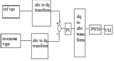
[image:4.595.308.500.452.540.2]In PI controller the gain values are adjusted to get optimum performance. These gain values can be tuned based upon Ziegler Nichol’s tuning or even by using Fuzzy controller [29]. Proportional and integral controller helps to reduce error values as fast as possible. PWM is based on equal area theorem. This technique uses sinusoidal PWM. The equal area theorem can be applied to realize any shape of waveforms. Equal area theorem states that responses tend to be identical when input signal has same area and time durations of input signals become small. Figure3. shows the basic control algorithm developed. It briefly describes about the importance of reference frame theory and PI controller. In Pulse Width Modulation technique, suitable signal from PI controller has been generated as control signal which makes to produce desire reference signal so that corresponding carrier signal is produced. The carrier frequency is set in PWM block. So that appropriate pulse signal is created which acts as an input to power switch and Voltage Source Converter. Pulse width Modulation is able to control the switching device IGBT. Here reference signal is otherwise said to be modulating signal which is made to compare with carrier triangular signal. Then according to that signal, ON-OFF pulse occurs simultaneously with corresponding delay due to synchronization.
Figure 3: Block diagram of controller
4.1 Fuzzy Logic Control
The fuzzy logic controller is used by replacing PI controller. Better performance can be observed using fuzzy logic controller for power quality improvement [21]. It is a tool which deals with uncertainty and provides a technique to deal with imprecision. The fuzzy theory provides a mechanism for representing linguistic constructs such as many, low, medium and high. In fuzzy logic basic control is determined by a set of linguistic rules. The following steps involved in control algorithm are given below.
Stage 1: Error Calculation
Error is calculated on the basis of difference betweenreference and fluctuated voltage. Error rate is calculated as Vref – Vfluctuated.
Stage 2: Fuzzification
Fuzzification is the process where the crisp quantities are converted to fuzzy. It converts non fuzzy (numeric) input variables to fuzzy set (linguistic variable). The membership functions is defined as error and change in error as Positive Big (PB), Positive Small (PS), Positive Medium (PM), Zero, Negative Small (NS), Negative Medium (NM), Negative Big (NB).
Stage 3: Decision Making
The set of rules for fuzzy are represented below: There are 49 rules for fuzzy controller. The output is based on the evaluation of rules by the fuzzy sets and fuzzy logic operation.
Step 4: Defuzzification
Defuzzification means conversion of fuzzy set to crisp value. It can be achieved using defuzzification process. Centroid method is used in this simulation study.
Step 5: Signal Processing
[image:4.595.95.286.476.578.2]The outputs of FLC process are the control signals that are used in generation of switching signals of the PWM inverter by comparing with a carrier signal.
Figure 4: Overall Block diagram of wind farm connected with power grid
5. SIMULATION RESULTS
[image:5.595.296.518.75.245.2]The system parameters are given in Table 1. It is used to verify the effectiveness of the SVC and STATCOM with PI and Fuzzy. The simulations were accomplished using Matlab Simulink
Table 1: System Parameters
Parameters
Values used in the Simulation Models Main supply voltage 480 V
Line frequency 60 HZ Source Impedance Ls=16.59 mH
Rs= 0.8928 Ω Injection
Transformer Turns ratio
1:1
PI Controller
Kp=0.1
Ki=2
Capacitor in STATCOM
1 micro Farad
Load 10 MW, 12MVAR Inverter IGBT based, 3
arms, 6 pulse Carrier frequency =
10000 Hz Asynchronous
generator
Stator resistance = 0.016 ohm Stator inductance =
0.05H Nominal power
1MW Voltage = 480V Frequency = 60 HZ
Case 1:
[image:5.595.95.286.217.533.2]In the proposed system, the voltage sag occurs due to the three phase fault applied in the time interval of 0.03s to 0.08s. Below figure shows voltage sag in the grid side as this work mainly focus on grid side.
Figure 5: Voltage sag due to three phase fault (0.03s to 0.08s)
Figure 6: Real power in grid during fault
[image:5.595.307.512.294.400.2]Figure 6 represents real power across grid without compensation. During the fault time 0.03 to 0.08s, oscillations are little high and at once fault time at 0.08s is cleared it starts to settle.
Figure 7: Reactive power in grid during fault before compensation.
Figure 7 represents that during fault time there is severe dip in reactive power along grid.
Case 2: In figure 8 the simulation is carried out
[image:5.595.306.508.525.650.2]with compensation technique using PI Controller. The sag is mitigated by using SVC with PI Controller. The mitigated output waveform is shown below. During the fault time voltage has been increased up to 338V.
[image:5.595.89.288.626.724.2]Figure 9: Real power in grid after compensation
Figure 9 Shows waveform of real power after compensation across the grid.
Figure 10: Reactive power in grid after compensation using SVC.
Figure 10 represents waveform of reactive power after compensation with SVC across grid side during fault. Reactive power gets compensated after placing SVC.
Case 3: The figure shows the simulation carried out
[image:6.595.306.517.349.470.2]with compensation technique using STATCOM. In the proposed system, the sag occurs due to the three phase fault applied in the time interval of 0.03s to 0.08s in the wind turbine side which is connected to power grid. Here voltage sag is mitigated by reactive power compensation across power grid. When compared to SVC, STATCOM has better performance and improvement.
Figure 11: Grid voltage after compensation using STATCOM
Figure 11 depicts the waveform of voltage on grid side after the compensation of STATCOM. Statcom
provides reactive power compensation and make the system to maintain voltage even under fault condition.
Figure 12: Real power in grid after compensation using STATCOM.
The above figure represents real power across grid after compensation with the help of STATCOM. The curve becomes smooth after fault clearing time about 0.08s.
Figure 13: Reactive power in grid after compensation using STATCOM.
Case 4: The simulation is carried out using FUZZY
[image:6.595.306.516.538.647.2]LOGIC technique and the improvement has been achieved by replacing PI controller.
Figure 14: Voltage in grid using Fuzzy logic technique.
[image:6.595.89.289.587.718.2]Figure 15: Real power in grid using Fuzzy logic technique.
Due to its easy and fast adaptive nature in fuzzy the oscillations has been completely removed and better real power is achieved than PI controller.
Figure 16: Reactive power in grid using fuzzy logic controller.
Reactive power across grid also shows drastic change that settling time is reduced and gets smooth waveform which is the major reason for voltage regulation.
6. CONCLUSION
In this work, test system is developed using matlab Simulink software. It is shown that power quality improvement is achieved successfully with SVC and STATCOM. This work shows that both devices can compensate the voltage sag and support to stabilize the wind farm connected to grid. Compared to SVC, STATCOM performs fast and takes lesser time for clearing of faults, but oscillations are more in STATCOM compared to SVC. In the proposed system, a FACTS device with PI controller is designed to decrease voltage fluctuations and to improve power quality. The control scheme is further improved by using Fuzzy logic controller and voltage sag is minimized. Better results are achieved and comparisons of results are made with PI and Fuzzy controller. Advanced control technique such as Fuzzy results better when compared to SVC. If the controller is
replaced further by ANFIS then problems such as harmonics, power factor can also be corrected.
REFRENCES:
[1] M.Liserre, R. Cardenas, M. Molinas, and J. Rodriguez, “Overview of multi-MW wind turbines and wind parks,” IEEE Trans. Ind.
Electron, 58, April. 2011, vol. 58, no. 4, pp.
1081–1095.
[2] Tascikaraoglu A, Uzunoglu M, Vural B, Erdinc O. “Power quality assessment of wind turbines and comparison with conventional legal regulations: a case study in Turkey”. Applied
Energy, 2011; 88: 1864–72.
[3] M. Tsili and S. Papathanassiou, “A review of grid code technical requirements for wind farms,” IET Renewable Power
Generation.,September 2009, vol. 3, no. 3, pp.
308–332.
[4] Wang, Jiaxin Ning. “Development of low voltage ride through control strategy for wind power generation using real time digital simulator”. Power system conference and
exposition, 2009. IEEE/PES.
[5] Hafidz SA, Basu KP. “Ride through capabilities of load during voltage sag/swell and power interruption with zigzag transformer”. In: Innovative technologies in intelligent systems
and industrial applications, 2008, IEEE
conference.
[6] Heping Zou, Hui Sun, Jiyan Zou. “Fault ride through performance of wind turbine with doubly fed induction generator”. In: Industrial
electronics and applications, 2nd IEEE
conference; May 2007.
[7] Marta Molinas, Friedrich Wilhelm Fuchs, “StatCom Control at Wind Farms with Fixed Speed Induction Generators under Asymmetrical Grid Faults” IEEE Transactions
on Industrial Electronics vol. 60, no. 7, July
2013.
[8] Li S, Ding M, Wang J, Zhang W. “Voltage control capability of SVC with var dispatch and slope setting” Electric Power System 2009; 79(5):818–25.
[9]Mendil. B, “Contribution to the improvement of voltage profile in electrical network with wind generator using SVC device” applied on
Renewable energy, 2010. pp.243-248.
[10]A.R.Boynuegri, B. Vural, A. Tascikaraoglu, M. Uzunoglu, R. Yumurtac “Voltage regulation capability of a prototype Static VAr Compensator for wind applications”, Applied
[11]Cidras J, Feijoo AE. “A linear dynamic model for asynchronous wind turbines with mechanical fluctuations”. IEEE Transaction on Power
System 2002; vol. 17(3): pp.681–687.
[12] Sharad W. Mohod, Mohan V. Aware “A STATCOM-Control Scheme for Grid Connected Wind Energy System for Power Quality Improvement” IEEE Systems Journal, Vol. 4, No. 3, September 2010.
[13]C. Wessels, F. Fuchs, and M. Molinas, “Voltage control of a statcom at a fixed speed wind farm under unbalanced grid faults,” in Proc. 37th
IEEE IECON, November. 2011, pp. 979–984.
[14]B. Singh, S. Murthy, and S. Gupta, “Statcom-based voltage regulator for self-excited induction generator feeding nonlinear loads,”
IEEE Transaction Electron, vol. 53, no. 5,
October. 2006. pp. 1437–1452.
[15] A. Ortiz, T. Ostrem, and W. Sulkowski, “Indirect negative sequence voltage control for STATCOM supporting wind farms directly connected to the grid,” in proc. IEEE 37th
IECON, November. 2011, pp. 1903–1908.
[16] Kenan Dosoglu, Aliozturk, “Investigation of different load changes in wind farm by using FACTS devices,” applied Energy Conversion, 2012, pp. 422–431.
[17] M. Molinas, J. A. Soul, and T. Undeland, “Low voltage ride through of wind farms with cage generators,” STATCOM versus SVC.IEEE
Transaction on Power Electronics, vol.23, no.3,
2008, pp.1104–1117.
[18]S. Alepuz, S. Busquets-Monge, J. Bordonau, J. Martinez-Velasco, C. Silva, J. Pontt, and J. Rodriguez, “Control strategies based on symmetrical components for grid-connected converters under voltage dips,” IEEE Trans.
Ind. Electron., vol. 56, no. 6, June 2009.pp.
2162–2173.
[19] P. Rodriguez, A. Luna, G. Medeiros, R. Tedorescu, and F. Blaabjerg, “Control of statcom in wind power plants based on induction generators during asymmetrical grid faults,” in Proc. IPEC, June. 2010, pp. 2066– 2073.
[20] N. Hoffmann, R. Lohde, M. Fischer, F. Fuchs, L. Asiminoaei, and P. Thogersen, “A review on fundamental grid-voltage detection methods under highly distorted conditions in distributed power-generation networks,” in Proc. IEEE ECCE, September. 2011, pp. 3045–3052 [21] Al-Kandari AM, Soliman SA, Alammari RA.
“Power quality analysis based on fuzzy estimation algorithm”: voltage flicker
measurements. Electron Power Energy System
2006; 28(10):723–8.
[22] Yanmaz Kenan, Ismail H. Atlas “Reactive power of control loads control with STATCOM fuzzy logic”. VII. National clear energy
conference; 2008. pp. 75–82.
[23] V ladimiro Miranda, “An improved Fuzzy Inference System for Voltage / VAR control”
IEEE Transactions on Power Systems,
November 2007 vol.22, No.4.
[24] A.Ghafori, M.R.Zolghadri and M.Ehsan, “Fuzzy controlled STATCOM for improving the Power System Transient Stability”, IEEE
international conference on Power system,
2001, pp.1178 – 1185.
[25]Ackermann T. “Wind power in power systems”.
John Wiley & Sons: Chichester, 2008.
[26]N.G.Hingorani and L. Gyugyi, “Understanding FACTS,” IEEE Press, Newyork, 1999.
[27]H. J. Bollen, “Understanding Power Quality Problems, “New York: IEEE Press, 2000. [28]S.N.Sivanandam, S.Sumathi and S.N.Deepa,
Introduction to Fuzzy Logic using MATLAB,
Springer-Verlag Berlin Heidelberg 2007.
[29] B. Ferdi, C. Benachaiba, S. Dib, R. Dehini “Adaptive PI Control of Dynamic Voltage Restorer Using Fuzzy Logic” Journal of Electrical Engineering: Theory and Application

![Figure 2: Schematic diagram of STATCOM The negative sequence effect caused by wind turbine on grid can be eliminated by voltage control capability of STATCOM [15]](https://thumb-us.123doks.com/thumbv2/123dok_us/8913165.960379/3.595.327.481.205.303/figure-schematic-statcom-negative-sequence-eliminated-capability-statcom.webp)