•
UNISYS
XE500
BTOS
Administration
Guide
Copyright @ 1988 Unisys Corporation All Rights Reserved
Unisys is a trademark of Unisys Corporation
Relative to Release Level 7.0
Priced Item
May 1988
The names, places and/or events used in this publication are not intended to correspond to any individual, group, or association existing, living or otherwise. Any similarity or likeness of the names, places, and/or events with the names of any individual living or otherwise, or that of any group or association is purely coincidental and
unintentional.
NO WARRANTIES OF ANY NATURE ARE EXTENDED BY THE DOCUMENT. Any product and related material
disclosed herein are only furnished pursuant and subject to the terms and conditions of a duly executed Program Product License or Agreement to purchase or lease equipment. The only warranties made by Unisys, if any, with respect to the products described in "this document are set forth in such License or Agreement. Unisys cannot accept any financial or other responsibility that may be the result of your use of the information in this document or software material, including direct, indirect, special or consequential damages.
You should be very careful to ensure that the use of this information and/or software material complies with the laws, rules, and regulations of the jurisdictions with respect to which it is used.
The information contained herein is subject to· change without notice. Revisions may be issued to advise of such changes and/or additions.
About This Guide
This guide explains how to administer the XEBTOS operating system after it has been installed.
Who Should Use This Guide
This guide will help you if you are an experienced user of XEBTOS or an experienced administrator of another operating system. You should be familiar with the XE500 BTOS Operations Guide.
How to Use This Guide
If you are performing XEBTOS administrative tasks for the first time, you should read sections 1 and 2. They contain basic information you will need for understanding your role and executing master commands.
By scanning the contents and reviewing the topics before you start, you may find this guide easier to use. To find definitions of unfamiliar words, use the glossary; to locate specific information, use the index.
In addition, you may want to review the XE500 BTOS
Operations Guide for an overview of user operations.
How This Guide is Arranged
vi About. This Guide
Conventions
The following conventions apply throughout this guide:
o
Names of processor boards (such as CP) refer to bothstandard boards and X boards (such as CP .... X).
o When two keys are used together for an operation, their names are hyphenated (for example, CODE .... D).
o In the tape file formats, half .... inch tape file names appear in the format
[tapexy]m
in which x, y, and m are variables. In this particular example, x, y, and m represent numerical values determined by a specific tape drive and file mark. o In BTOS command forms, optional fields and
parameters are enclosed in square brackets .
. 0 Numbers are decimal unless they have the suffix h for
hexidecimal (for example, lOOh).
Reference Material
This guide contains two appendixes, a glossary, and an index.
o For definitions of the various types of status codes the system can report, refer to appendix A.
o
For information on disk naming conventions, processor naming conventions, and board slot numberconventions, refer to appendix B.
o
For definitions of key terms used in this guide or related to the software, refer to the glossary.Related Product Information
For information on creating customized versions of the operating systems that run on XE520 processors, refer to the BTOS II Customizer Programming Guide.
For a complete list of system status codes, with definitions and, if applicable, suggestions on how to recover, refer to the BTOS II System Status Codes Reference Manual. For a description of how to use the Debugger, refer to the
For information on installing and implementing XEBTOS system software, refer to the XE500 BTOS Installation and
ImplementatiQn Guide.
For information on the XEBTOS tasks routinely performed by anyone using the XE520, refer to the XE500 BTOS Operations Guide.
For a description of the XEBTOS system software and XE520 hardware features, refer to the XE500 BTOS System
Contents
About This Guide •••••••••••••••••••••••••••••••••••••
Who Should Use This Guide ••••••••••••••••••••••••••••• How to Use This Guide •••••••••••••••••••••••••••••••••• How This Guide Is Arranged ••••••••••••••••••••••••••••• Conventions ••••••••••••••••••••••••••••••••••••••••••• Reference Material ••••••••••••••••••••••••••••••••••••• Related Product Information ••••••••••••••••••••••••••••
Section 1: Overview ••••••.•••••.•.••.•••••••••••...••
Section 2: Using Master Utilities and Master
Commands •...•.•.••..••..••..••••••.•••.•••.••••••••
Commands and Utilities ••••••••••••••••••••••••••••••••• Running Master Utilities •••••••••••••••••••••••••••••••• Using a Master Command •••••••••••••••••••••••••••••••
Moving the Cursor within a Command Form •••••••••••••••• Optional Fields •••••••••••••••••••••••••••••••••••••••• Executing a Master Command •••••••••••••••••••••••••• Section 3: Initializing and Verifying XE520 Disks ••.•.•
Overview of XE520 Disks, Volumes, and File Systems ••••••
Disk Drive Device Names ••••••••••••••••••••••••••••••••• Volume Names ••••••••••••••••••••••••••••••••••••••••• The XEBTOS File System-and File Names ••••••••••••••••••
Overview of Volume Initialization ••••••••••••••••••••••••
Volume Fragmentation ••••••••••••••••••••••••••••.•••••••
Initializing XE520 Volumes ••••••••••••••••••••••••••••••
Guidelines for Initializing a Volume •••••••••••••••••••••••• Bad Spots •••••••••••••••••••••••••••••••••••••••••••••• Identifying Bad Spots •••••••••••••••••••••••••••••••••• Listing Current Bad Spots •••••••••••••••••••••••••••••• Entering Bad Spots •••••••••••••••••••••••••••••••••••• Note About Bad Spots •••••••••••••••••••••••••••••••••
Executing the BAD SPOT REPORT Command •••••••••••••• Reducing Fragmentation with the mDisk Squash Utility ••••
Executing the MDISK SQUASH Command •••••••••••••••••• Section 4: Managing XE520 File Systems •.••••• ~ •••••
Assigning Volume Names and Passwords ••••••••••• ~ ••••• Changing System Disk Volume Name and Password •••••••• Getting Volume Status Information ••••••••••••••••••••••• Creating Directories •••••••••••••••••••••••••••••••••••• Removing Directories ••••••••••••••••••••••••••••••••••• Setting Directory Security •••••••••••••••••••••••••••••••
x . Contents Section 5: Establishing System and File Security... 5·1 Tools for Establishing Security.. •••• ••• • •••• ••••• •• • ••• • • 5·1 File Security. • • • • • • • • • • • • • • • • • • • • • • • • • • • • • • • • • • • • • • • • • • • 5·1 Assigning Protection Levels. • • • • • • • • • • • • • • • • • • • • • • • • • • • • 5·1 Passwords ••••••••••••••••••••••••••••••••••••••••••• 5·3 Accessing Password-Protected Files • • • • • • • • • • • • • • • • • • • • • 5·5 Passwords in a File Specification • • • • • • • • • • • • • • • • • • • • • • • • 5·5 User's Default Password •• • •• • • • • • • • • • • • • • • • • • • • • • • • • • • 5·6 User Signon Files •••••••••. 0 • • • • • • • • • • • • • • • • • • • • • • • • • • • • • 5·6
Controlling Access to Master Utilities •••••••••••••••••••••• 5·6 Guidelines for Establishing System Security. • • • • •• • • • • • • • • 5·7 System User Classes and Security Levels •• 0 0 • 0 0 • • 0 0 " . 0 • 0 • • • 5·8
Single-Program User ••• 0 • • • • • • • • • • • • • • • • • • •..• • • • • • • • • • • 5·8
Command Subset Users •••••••••••••••••••••••••••••• '. • 5·9 System Administrator. • • • • • • • • • • • • • • • • • • • • • • • • • • • • • • • • • 5·10 Protection Levels for System Files... • • • • • • • • 5·10
Section 6: Managing File System Archives. . . 6·1 Types of Archive Media • • • • • • • • • • • • • • • • • • • • • • • • • • • • • • • • • 6-1 Using Archive Commands •••••••••••• 0 • • • • • 0 • 0 0 • • • • • • • • • 6·1
Archiving with Tape ••• 0 • • • • • • • 0 0 0 • • • • 0 0 0 0 0 0 • 0 0 • 0 0 • • 0 . 0 . 0 6·2
The Backup Operation 0 • • • • • • • • 0 • • • • • • • • • • • • • • 0 • • • • • • • • 0 • 6·2
Retensioning QIC Tapes •••• 0 • • • • • • 0 • • • • 0 • • 0 0 • • 0 • • • • • • • • • • 6·2
Multiple Backups on One Tape... • ••• •••• •• ••• •• • • • 6·3 Backup to Multiple Tapes •••••••••••••••••••••••••••••••• 6·3 Reusing Archive Tapes. • • • • • • • • • • • • • • • • • • • • • • • • • • • • • • • • • • 6·3 Backing up an XE520 Volume to Tapes •••••••••••••••••••• 6-4 Backing up Selected Files to Tapes... • •• • • ••• •• •• • ••• • • 6·8 Restoring Files from Tapes ••••••••••••••••••••••• 0 . • • • • • • 6·10
How Tape Utilities Manage Backup and Restore Tape Errors.. 6·15 Scheduling Backup Operations... ••• •••••••••• ••••••• • 6·16 Examples of Backing Up and Restoring Files... •••••• • • 6·16 Examples of Backing Up Files... ••• ••• • • 6·17 Example 1 .•.•••••••..••..•.•••..••••••.•.•..•.•••..• 6·17 Example 2 ••••••••••••••••••••••••••••••••••••••••••• 6·18 Example 3 ••••••••••••••••••••••••••••••••••••••••••• 6·19 Example 4 .•...••..••..•..•..•••.••...•..••••••.••••. 6-20 Sample Restore Operations. • • • • • • • • • • • • • • • • • • • • • • • • • • • • • • 6·21 Restoring All Files on the Archive Tape.. ••••••••• ••• ••• • • 6-21 Restoring Selected Files on the Archive Tape... ••••••• • 6·21 Duplicating Release Software. • • • • • • • • • • • • • • • • • • • • • • • • • • • 6·22
Synchronizing the installation 01 System Services. • • • • .. • • • • • • "1 ~5 Monitoring Synchronized System Service Installation ... ., ~6
Removing Secondary Partitions •••••• 0 0 • • " . . . " " " . . . 0 .. • 1 ~ 1
Getting Partition Status Information ... ".... ... •••••••• 1·7
Section 8: Managing Cluster Activity... 8~1 Disabling Cluster Lines ••••••• , ... " • • • • • • • .. • • • • .. • • • • .. • • 8·1
Resuming Cluster Activity. • • • • • • • • • • • • .. • .. • • • • • • • • • • • • • • • 8·3
Section 9: Using the Command Line Interpreter... 9·1
How Cli Works. • • • • • • • • • • • • • • • • • • • • • • • • • • • • • • • • • • • • • • • • 9·2 Communicatlnl with the CLI ... 9-4 Using Processor Initialization Files... • • • • • • • • • • • • • • • • • • • 9·4
Using Cli Ports.. • • • • • • • • .. • • • • • • • • • • • .. • • • • • • • • • • • • • • • • • • 9·5
Using the mCdtlO Utility • • • • • • .. • • • • • • • • • • • • • • • • • • • • • • • • • • 9·5
Executing MCdtlO Through the Executive. • • • • • • • • • • • • • • • • 9·6
Executing mCdtlO Through a
eLi
Port.... • • ... ... 9·8Terminating an mCdtlO Utility Session. • • • • • • • • • • • • • • • • • • 9·8
Using the mCIi Utility.. • • • • • • • • • • • • • • • • • • • • • • • • • • • • • • • • • • 9·8
Terminating an mCIi Utility Session... ••• •• •• ••••••••• • 9·8
Cli Command Syntax. • • • • • • • • • • • • • • • • • • • • • • • • • • • • • • • • • • 9·9
Command Form... • • • • .. • • • • • • • • • • • • • • • • • • • • • • • • • • • • • • 9·9 Special Characters... ••••• ... • •• • •• •• ••• •• ••• •••• 9·10
Continuation Lines. •• •• • • ••• • •• • • • •• ••• • •• •• •• • ... ••• •••• 9·10
Comments. • • • • • • • • • • • • • • • • • • • • • • • • • • • • • • • • • • • • • • • • • • • • 9·10
Call Parameters. • • • • • • • • • • • • • • • • • • • • • • • • • • • • • • • • • • • • • • • • 9·11
File'Name Conventions ... " .... " •••••••• "... 9·11
Using Cli Commands. • • • • • • • • • • • .. • • • • • • • • • • • • • • • • • • • • • • 9·11
Executing a Run File ... "... 9·12 Calling JCL Files for Execution ••••• • • • • • • • • • • • • • • • • • • • • • • • 9·13
Ending a JCL File. " • " ••• J . . . " .... " • • • • " • • • • • • • • • • • • • .. • • • • • 9814
Terminating Execution of JCL Files. •••••• • •• •••• ••• ••••••• 9814 Changing the Path. •• •••• ••• • •• •••••••• • •• •• •• ••••• • •••• ge15
Loading a Run File during a Oebugger Session... 9·16 Cli Status MesSilges ••••••••••••••••••••••••••••••••••• 9-16
Section 10: Monitoring XE520 Processor Activity... 10~1 Monitoring a ProcessorWs CPU Ac:tlvlty .". ~ • • • • • • • • • • • • • • • lao 1
Monitoring Processor Intercommunications. • • • • • • • • • • • • • • 10·5
Executing the MPSTAT Command... 10·6
Using the MPSTAT Command Statistics... 10·11
Section 11: Running the System In Different
xii Contents
Using the Restricted Mode... ••• •••• ••••••• ••• • 11.3 Capabilities of the Restricted Mode.. •••• •••••••••• ••••••• • 11·3 Error Logging. •• • •• • •• • • •• • •• • • • •• • • •• • • • • •• • • •• . •• • • •• • 11·4 Using Customized Modes.. • • • • • • • • • • • • • • • • • • • • • • • • • • • • • • 11·4 Section 12: Analyzing and Recovering from Error
Conditions •••...•••.••••••..•••••••...••... Troubleshooting Tools •••.•••••••••••••••••••••••••••••• Front Panel STATUS Display ••••• ~ ••••••••••• ~ •••••••••••• BTOS Status Codes •••••••••••••••••••••••••••••••••••••• System Crash Status Words •••••••••••••••• " •••••••••••••• The System Log ••••••••••••••••••••••••••••••••••••••••• Listing the System Log ••••••••••••••••••••••••••••••••• System Crash Reports ••••••••••••••••••••••••••••••••• System Boot Reports •••••••••••••••••••••••••••••••••• System Initialization Error Reports •••••••••••••••.••••••• Disk I/O Error Reports ••••••••••••••••••••••••••••••••• Cluster Communication Error Reports •••••••••••••••••••• ISAM Error Reports •••••••••••••••••••••••••••••••••••• Tape Operations Status and Error Reports •••••••••••••••• Crash Dumps ••••••••••••••••••••••••••••••••••••••••••• Status Codes on Processor LEOs •••••••••••••••••••••••••• Waiting to Boot ••••••••••••••••••••••••••••••••••••••• Boot ROM Status Codes ••••••••••••••••••••••••••••••• Crash Codes for BTOS Processors. • • • • • • • • • • • • • • • • • • • • • • . Analyzing System Status •••••••••••••••••••••••••••••••• System Start-Up ••••••••••••••••••••••••••••••••••••••• What Happens during System Start-up ••••••••••••••••••• System Start-Up Problems ••••••••••••••••••••••••••••• Common User and System Errors •••••••••••••••••••••••••• Intermittent System Crashes •••••••••••••••••••••••••••••• RS-232-C Serial Communications Problems •••••••••••••••• Cluster Communications Problems ••••••••••••••••••••••••• Disk Drive ProblemsDisk drive •••••••••••••••••••••••••••• Recovering from System Problems ••••••••••••••••••••••• Using the Restricted Mode ••••••••••••••••••••••••••••••• Determining Corrupted System Files ••••••••••••••••••••••• Running the System in a Degraded Mode ••••••••••••••••••• Section 13: Reporting Problems .•••••.••••..•.••..••.
Appendix A: Status Code Tables ... . Kernel ••••••••••••••••••••••••••••••••••••••••••••••••• Device Management •••••••••••••••••••••••••••••••••••• Allocation (BTOS) •••••••••••••••••••••••••••••••••••••• Printer Spooler ••••••••••••••••••••••••••••••••••••••••• Tape Management (BTOS) ••••••••••.•••••••.•••••.••.•• BTOS System Requests ••••••••••••••••••••••••••••••••• System Start-up/Initialization Sequence •••••••••••••••••• Disk Hardware Error Codes ••••••••••••••••••••••••••••••
Processor Error Codes. • • • • • • • • • • • • • • • • • • •• • • • • • • • • • • • • • A·l2 Software Error Codes... • ••• •• • • •••• • •• • ••••••• ••• •• •••• A·l3 Expansion Enclosure Error Codes... A·l3 Codes Displayed While STATUS Display Is at 01... A·l3 Codes Displayed When STATUS Display Is at 39... A·l4 Bad Media Error Codes Displayed When STATUS Display Is
at 21. • • • • • • • • • • • • • • • • • • • • • • • • • • • • • • • • • • • • • • • • • • • • • • • • • A·lS Master DP·Speclflc Boot Medium Error Codes... A·lS Disk Hardware Error Codes ••••••••••••••••••••••••••••• A·16 Disk Hardware Error Codes Displayed When STATUS
Display Is at 39 • • • • • • • • • • • • • • • • • • • • • • • • • • • • • • • • • • • • • • • • A-l6 Master DP-Speclflc Disk Hardware Error Codes Displayed
When STATUS Display Is at 39 •••••••••••••••••••••••••• A-l6 General Status Codes... •••••• • .••••••••••.••••••••••••• A-l7
Hardware Configuration Information. . .• . . . .. . .. ••.• B-1
Glossary ...••...•...•...•.•...•....•..• Glossary-1
Figures
3-1 MIVOLUME Command Form •••••••••••••••••• 3-6
3-2 BAD SPOT REPORT Command Form •••••••••• 3·18
3-3 MDISK SQUASH Command Form ••••••••••••• 3·20
3-4 Sample mDisk Squash Report ••••••.•••••••••• 3·22
4-1 MCHANGE VOLUME NAME Command Form •• 4·2
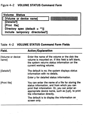
4-2 VOLUME STATUS Command Form •••••••••••• 4·6
4-3 Sample Volume Status Report •.••••••..•••••• 4-7
4-4 MCREATE DIRECTORY Command Form ••.•••• 4·8
4-5 MREMOVE DIRECTORY Command Form •••••• 4·11 4-6 MSET DIRECTORY PROTECTION Command
Form •.••.•••...•..••.•••..•..•••.••.••••••• 4·13
6-1 MTAPE BACKUP VOLUME Command Form ••• 6·5
6-2 MTAPE SELECTIVE BACKU P Command Form. 6·9
6-3 MTAPE RESTORE Command Form •••••••••••• 6·12
6-4 Sample MTAPE BACKUP VOLUME Command
Form ••..•.•..••..•.••••••••••.•.•••.••••••••• 6·17 6-5 Sample MBACKUP VOLUME Command Form. 6·18 6-6 Sample MSELECTIVE BACKUP Command
Form •.••..•...•...•••••..••...••.••.••• 6·19 6-7 Sample MTAPE SELECTIVE BACKUP
Command Form ..••..•..•...•...•••••••.•• 6·20 7-1 MINSTAll SER.VER Command Form ••.••.•••• 7·4 7-2 MPARTITION STATUS Command Form •.••.•• 7·9 8-1 MDISABlE CLUSTER Command Form ..•••.•• 8·2 9-1 Processor Initialization File Execution •••••.••• 9·3 9-2 MCDTIO Command Form ••.••...••....•.••••• 9-6 10-1 MHISTOGRAM Command Form ... 10·3 10-2 Sample mHistogrammer Report ..••..••••••••• 10-5 10-3 MPSTAT Command Form •••••••.•.••••.•••.•• 10·7 10-4 Sample mPStat Statistics for ICC and Disk •••• 10·9 12-1 MPERC Command Form ••••••••.••••••.•••••• 12·3 12-2 PLOG Command Form •••••.•••...•••••••••••• 12·6 12-3 Sample Plog System Crash Reports .••••••••• 12·8 12-4 Sample Plog System Boot Reports ••••.•••..• 12-9 12.-5 Sample Plog System Initialization Error·
Report •.••.••.•••..••..•.••..•••...•••.••••..• 12·10 12-6 Sample Plog Disk I/O Error Report ••••.•••.•• 12·11 12-7 Sample Plog Cluster Communications Error
xvi Figures
12-8 Sample PLog Tape Operations Status
Report •••••••••••••.•.•••••••••••••••••••••• 12·13
12-9 Sample Plog Tape Operations Error Report • 12·14
12·10 Reading Boot ROM Error Codes on Master
Processor LEDs ••••••••••••••••••••••••••••• 12·17
12-11 Sample Processor LED Crash Code
Sequence ••••••••.••••••..••..••••••••••••.. 12·19
B-1 Built-In Disk Device Naming Conventions •• A·l
B-2 Built-in Disk Device Naming Conventions
for DPOO ••••••••••••••••••••••••••••••••••• 8·2
Tables
3-1 MIVOLUME Command Form Fields ••.••••••••• 3·7
3-2 BAD SPOT REPORT Command Form Fields ••• 3·18
3-3 MDISK SQUASH Command Form Fields .•••••• 3·21
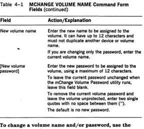
4-1 MCHANGE VOLUME NAME Command Form
Fields •••••.•...•••••••••••••••••.••..•••••.•.• 4·2
4-2 VOLUME STATUS Command Form Fields ••••• 4·6
4-3 MCREATE DIRECTORY Command Form
Fields •••••••••••.•••••••••••••••••••.••••••••• 4·9
4-4 MREMOVE DIRECTORY Command Form
Fields •••••.•••••••••••••••••••••.•••.••.••.••• 4·12
4-5 MSET DIRECTORY PROTECTION Command
Fields ••••••••••••.••••••••••••••.••••••••••••• 4·14
5-1 BTOS Password Protection Levels ••••••••••••• 5·2
5-2 Suggested Protection Levels for System Flies. 5·10
6-1 MTAPE BACKUP VOLUME Command Form
Fields •••••.••••••.•••••••••••••••••••••••••••• 6·6
6-2 MTAPE SELECTIVE BACKUP Command Form
Fields •.•••.••••••••••••••••••.••.••••••••••••• 6·9
6-3 MTAPE RESTORE Command Form Fields •••.• 6·13
7-1 MINSTALL SERVER Command Form Fields •••• 7·4
7-2 MPARTITION STATUS Command Form Fields. 7·9
8-1 MDISABLE CLUSTER Command Form Fields •• 8·2
8-2 MDlsable Cluster Line Numbers •••••.••••••••• 8·3
9-1 MCDTIO Command Form Fields •.••...•.•••••• 9·7
9-2 CLI Commands ••••••••••••••••••••••••••••••• 9·12
10-1 MHISTOGRAM Command Form Fields •••••••• 10·3
10-2 MPSTAT Command Form Fields •••••.••••••••• 10·8
10-3 mPStat ICC Statistics ••••••••••••••••••••••••• 10·9
10-4 mPStat Disk I/O Statistics •••••••••••••••••••• 10·10
12-1 PLOG Command Form Fields •••••••••••••••••• 12·6
A-I System Crash Status Word •••••••••••••••••••• A·18
A-2 General Status Register Contents ••••••••••••• A·19
Overview
As system administrator, you lu:tve acces~ to the co:mplete
range of XEBTOS software capabilities.
This section is a list of the administrative functions, which are dis(~ussed in detail in other sections of this guide or in
the o~her guide noted.
o installing system software (this is covered in the XE500
BTOS Installation and Irnplementation Guide)
o configuring system software to match your systemls hardware configuration (this is covered in the XE500
BTOS installation and lrnple1'nentatio7t, Guide)
o
initializing XE520 disk deviceso
managing the XEBTOS fHe systemsLJ Inaintaining archive files of the data in the XEBTOS file systems
[J iuanaging user access to system files and resources
o
managing applications that run in secondary partitionsOil XE520 processors
tJ controlling workstation cluster lines
[J using the Command Line Int€l"p.feter (eLI)
(J illOn1tufuig XE520 pl"ocesso~t acti vity
Ci running the system iil dlffel'ellt operating modes
i] interpreting and 1'€i;OV€l"illg frotH eam' (~(j.nditions
Using Master Utilities and Master
Commands
In addition to the local workstation BTOS utilities
described in your BTOS II Standard Software Operations
Guide, there are several utilities specific to the XE520
environment. These are master utilities, and you invoke most of them with master commands.
This section describes master utilities and master commands.
The administrative functions that use these commands are described in later sections of this guide. For a description of each master command function and its command form fields, refer to the XE500 BTOS Operations Guide, which also describes basic user operations that require these commands.
Because you use many of the master commands to administer the XE520 system, you should restrict user access to them. Section 6 describes the methods for controlling access to master commands.
The AdminAgent system service controls the execution of master utilities on XE520 processors, running one master utility at a time. Refer to the XE500 BTOS Installation and
Implementation Guide for information on configuring the
AdminAgent.
Commands and Utilities
The terms command and utility are sometimes used interchangeably, but a distinction exists between them. Command refers to the command name and command form used with the BTOS Executive mode. (For a complete description of the BTOS Executive, refer to your standard software operations documentation.) Utility refers to a program used internally by BTOS, usually as a result of a command.
2·2 Using Master Utilities and Master Commands
Running Master Utilities
For the most part, workstation utilities can· freely access XE520 resources. You can use these utilities to maintain the XE520 as you would a workstation.
Master utilities, however, execute on XE520 processors and can access XE520 resources only. Most master utilities are special versions of workstation BTOS utilities; however, some master utilities do not have corresponding
workstation utilities. These master utilities are used for resources specific to the XE520.
There are two ways to run master utilities:
o You can issue the corresponding command through the BTOS Executive. The Executive uses an XE520
AdminAgent to execute the command remotely at the XE520.
You can invoke master utilities from the Executive only if they have a corresponding command form and only if the AdminAgent has been configured to use them. o You can execute a utility's run file through the
Command Line Interpreter (CLI) using Job Control Language (JCL). Refer to section 9 for more information about the CLI.
In all cases, master utilities execute on an XE520 processor. When used as a master utility parameter, a volume name always refers to an XE520 volume.
Using a Master Command
The following subsections describe procedures and
conventions for using master commands. These commands are similar in operation to workstation BTOS commands.
Moving the Cursor within a Command Form
You can move through the fields of a command form by
Optional Fields
Command forms can contain optional fields, enclosed in square brackets. You need not fill out an optional field to execute a function.
Optional fields that accept yes or no answers are configured with a default value. Other types of optional fields either are configured with default values or do not require an entry. The command descriptions in the XE500
BTOS Operations Guide discuss the optional fields and
whether a field has a default value.
Executing a Master Command
To execute a master command, use the following procedure:
1 Enter the name of the master command at the BTOS Executive command line.
2 Choose one of the following:
o Proceed to step 4 to accept all system defaults or to activate a command that has no command form.
o
Press RETURN to display the command form. 3 Fill in the appropriate fields of the command· form. 4 Press GO.The system executes the command.
Normally the command sends messages to the worl{station screen to inform you of the command execution status. Depending on the command you use, the system can generate a a report or listing and send it to the screen. These commands usually provide the option of sending the report or listing to a printable file so that you can have a printed copy of the information.
For more information about individual master commands, refer to subsequent sections of this guide and to the XE500
Initializing and Verifying XE520
Disks
This section provides information and procedures for: o initializing disks to create new volumes
o
reinitializing disks to correct volume fragmentation or add new disk bad spot informationo
generating a listing of a volume's bad spots o verifying a disk's hardware and volume structureintegrity
Overview of XE520 Disks, Volumes,
and File Systems
Each XE520 disk must be initialized (formatted) before you can store data on it. An XE520 disk can be a built-in disk or a Storage Module Device (SMD) disk.
Note: In this guide, the term built-in disk refers to a 5 1/4-inch hard disk that a File Processor (FP) controls. An XE520 can have an SMD disk built into its base enclosure, but this disk is controlled by a Disk Processors (DP) and is
functionally different from other built-ins.
Once a disk is properly initialized to accept data, it is said to contain a volume. A disk is a hardware device; a volume is the complete file system unit of information stored on the disk. Each initialized disk in the system has a volume associated with it.
Because of this relationship, you can frequently substitute the device name of the disk drive for the volume name when referring to the information stored on the disk. Disk Drive Device Names
XE520 disk devices are named according to their physical location in the system. The name conventions are different for disks controlled by FPs (built-in disks) and for disks controlled by DPs (SMDs).
SMD disks controlled by the first DP in the system (DPOO)
are named sO through 85; SMDs controlled by the second DP in the system (DPOI) are named s6 through s11; and so on.
Appendix B contains information on disk naming schemes.
Disk ddve device names and passwords can be defined in;
o
the FP's and DP's operating systemsThese naJ1les and passwords are assigned when a processor's operating system is generated. For more information about these parameters and operating system generation, refer to the BTOS II Customizer Programming Guide.
o the FP's and DP's configuration files
For more information about these parameters in FP and
DP configuration files, refer to the XE500 BTOS
Installation and Implementation Guide,
Volume Names
Volume naming conventions for XE520 volumes are the same as for workstation volumes.
Yau assign a BTOS volume na.me to a disk when you initiaJize it with the mIVolume utility. Follow these rules when selecting a volume name~
o Use a maximum of twelve characters, including any alphanumeric eharacters, hyphens, and periods. o Do not duplicate any other BTOS volume or device
name,
o Do not use any of these as a volume nJ~,me; dO, dl, d2, d3, and so on; sO, 81, 82, s3, a.nd so on; Nul; or Kb.
o Do not use a volume nam.e that begjns wjth: Comm, Lpt,
Spl, Tape, Vid, or QIC,
The. XEBTOS File
System
8.nd
File Names
In canonical form, the BTOS file system has a four-level
structure:
o Node, A node is the name of ~l workstation or other point within a communications network
o Directory. Each volume can contain one or more
directories. All directories are at the same level (that is, a directory cannot contain another directory).
o File. Each directory can contain one or more files. A full BTOS file name has the following format: {node} [volname] <dirname> filename
node is the name of the point in the communications network where the file is stored. Specifying the node is optional; when not specified, it is assumed to be the local workstation or terminal.
vol name is the name of the volume on which the file is stored. You can normally use the disk name associated with the volume instead of the actual name of the volume.
If a workstation and an XE520 disk device or volume both have the same disk name or volume name, you precede the XE520 name with an exclamation mark (!).
dirname is the name of the directory in which the file is stored.
filename is the name assigned to the file.
Refer to your BTOS II Standard Software Operations
Guide for detailed information about file name
specifications.
Overview of Volume Initialization
The mIVolume (Initialize Volume) utility prepares an XE520 disk for use as a system volume. The mIVolume utility:
o formats the disk surfaces into 512-byte sectors o performs surface tests to identify defects
o writes volume control structures (Volume Home Blocks, Master File Directory, Allocation Bit Map, and File Header Blocks) onto the disk Volume Home Block Master file directory
o creates system files
3-4 Initializing and Verifying XE520 Disks
Built-in disks and MD3 disks are normally initialized before they are shipped to customers or by the field representative when the system is installed.
You need to reinitialize disks under certain conditions, such as:
o when system performance is degraded due to volume fragmentation (refer to Volume Fragmentation) o when system files or volume control structures are
unreliable due to disk bad spots
o to change the size of certain volume-based files for the designated system disk, such as the system image file, the log file, and the system crash file
o to change the maximum number of directories or files allowed on the volume
o to set the volume control structures to use primary headers only (as opposed to having primary and secondary headers)
o
to set protection for the <sys> directory o to enter new disk bad spotsAll disks come with a listing of known bad spots, or defective areas on the disk surface. When you initialize a disk for the first time, the system enters this list into a bad spot file, called badblk.sys, in the volume's <sys>
directory. The volume uses the bad spot list to track the areas where data cannot be stored.
The badblk.sys file is a coded file. The mIVolume and Bad Spot Report utilities generate a text listing of the bad spots.
Volume Fragmentation
BTOS volumes can become fragmented over time. When you create or extend files, BTOS tries to allocate a single disk extent to store the new data. (A disk extent is one or more contiguous disk sectors that make up all or part of a file.)
this case, the volume is said to be fragmented, because the system must allocate two or more smaller disk extents that have a total size sufficient to fulfill the request.
If a volume becomes fragmented, performance is affected several ways:
o The system requires more time to create or extend a file because it must access more sectors of the Bit
Allocation Map to find enough disk extents to satisfy the request.
o The system requires more time to process a file sequentially because disk sectors that are logically consecutive may not be physically consecutive.
o Fewer files can be open concurrently because each open file requires allocation of a File Area Block· in memory for each disk extent of that file.
You can correct this condition in two ways:
o You can back up the volume to archive tapes or disks and reinitialize the disk. When the archived data is restored, files are placed on contiguous disk extents. (For information about backing up and restoring files, refer to section 6.)
o You can consolidate multiple free areas on a disk using the mDisk Squash utility.
This utility does not consolidate a multiple-extent file into a single-extent file (as the backup, reinitialize, and restore operation does) but helps reduce the
fragmentation of the free areas on a disk.· Refer to Reducing Fragmentation with the mDisk Squash Utility.
Initializing XE520 Volumes
To format XE520 disks, you use the mIVolume utility. You also use it to:
o assign the volume name o assign the volume password
o determine the maximum number of directories and files that can be created on the volume
3·6 Initializing and Verifying XE520 Disks
o assign a password to the <sys> directory o determine whether the <sys> directory is to be
write-protected
o add to the volume's bad spot listing
To activate the mIVolume utility, you enter MIVOLUME at the Executive command line and press RETURN.
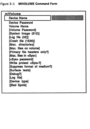
The system displays the MIVOLUME command form shown in figure 3-1.
Figure 3-1 MIVOLUME Command Form
mlVolume
I
Device Name Device Password Volume Name [Volume Password] [System Image (512)] [Log file (32)][Crash file (1536)) [Max. directories] [Max. files on volume] [Primary file headers only?] [Max. files in cSys>]
[cSys> password] [Write protect cSys>?]
[image:29.396.42.337.158.581.2][Suppress format of medium?] [Surface tests]
You must enter parameters in three MIVOLUME fields: o In the Device name field, enter the name of the device
that contains the volume you want to format.
D In the Device password field, enter the password for the device. Unless a user modifies it, the device password is the same as the device name.
D In the Volume name field, enter a name (a maximum of
12 characters) to identify the volume. This name must not duplicate any device or active volume name. The MIVOLUME command form has 16 optional fields (enclosed in square brackets). The defaults for these fields are set for a system volume. Refer to table 3-1 for
information about each optional field.
When you complete the MIVOLUME command form, you press GO. The initialization of the volume begins. You must respond to the prompts that appear during the
initialization procedure.
The mIVolume utility verifies the consistency of the parameters specified in the command form, opens a log file for the initialization operation (if a log file is specified), and displays the values chosen for the sizes of the volume control structures.
Table 3-1 MIVOLUME Command Form Fields Field Action/Explanation
Device Name Enter the physical device name of the disk drive to be initialized.
Device Password
Default names for XE520 built-in disk drives are dO, dl, d2, and so on.
Default names for SMD disk drives are sO, sl, s2, and so on.
Enter the password (if one exists) for the drive device. To assure system security, the password does not display as you enter it.
3-8 Initializing and Verifying XE520Dlsks
Table 3-1 MIVOLUMECommand Form Fields (continued) Field Action/Explanation
Volume Name Enter a name, with up to 12 characters, to be assigned to the volume. It must not contain
[Volume Password]
[System Image (def = 512)]
[ , ] , <, >, {, or 1, must not begin with a device name or Comm, CTOS, Kbd, Lpt, QIC, Spl, Sys, Tape, or Vid, and must not duplicate another volume name.
If you do not specify a password, the volume is unprotected. No password is necessary to access it, and none of its directories or files can have passwords.
To assign a password to this volume, enter a maximum of 12 characters. Depending on the file protection level assigned, users use this password when they create files or directories, or when they open files on this volume. You can assign or modify a volume's password later with the MCHANGE VOLUME NAME command.
This is the number of sectors required for a system image (that is, the master operating system run file).
For the XE520 system disk, the system image size should be at least 512 sectors.
To initialize a nonsystem disk, enter O. mlVolume creates an empty file,
[Sys]<Sys>Syslmage.sys, whose size is the specified number of sectors.
You cannot install or copy the Syslmage.sys file to an initialized volume without using mlVolume to allocate space for it. If the area for
Table 3-1 MIVOLUME Command Form Fields (continued) Field Action/Explanation
[log file (32)] Enter the number of sectors required for the system log file, [sys]<sys>log.sys. The default value is 32.
[Crash file (1536)]
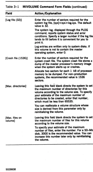
[Max. directories]
[Max. files on volume]
The system log, displayed through the PLOG command, reports system status and error conditions. Specify a larger number if the log file tends to fill before it is convenient for you to print it.
log entries are written only to system disks. If this volume is not to contain the master operating system, enter O.
Enter the number of sectors required for the system crash file. The system crash file stores a dump of the master processor's memory image when the system starts up or crashes.
Allocate two sectors for each 1 kB of processor memory to be dumped. For non-production systems, the recommended value is 1536 sectors.
Leaving this field blank directs the system to set the maximum number of directories for this volume according to the volume size. To specify your estimate of the maximum number of directories to be created, enter that number, which must be less than 65535.
You can reallocate a volume structure whose size is derived from this parameter only by reinitializing the volume.
leaving this field blank directs the system to set the maximum number of files for this volume according to the volume size.
[image:32.403.59.366.34.598.2]3-10 Initializing and Verifying XE520 Disks
Table 3-1 MIVOLUME Command Form Fields (continued)
Field Action/Explanation
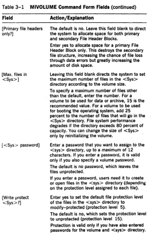
[Primary file headers only?]
[Max. files in <Sys>]
[<Sys> password]
[Write protect <Sys>?]
The default is no. Leave this field blank to direct the system to allocate space for both primary and secondary File Header Blocks.
Enter yes to allocate space for a primary File Header Block only. This destroys the secondary file structure, increasing the chance of file loss through data errors but greatly increasing the amount of disk space.
Leaving this field blank directs the system to set the maximum number of files in the <Sys> directory according to the volume size. To specify a maximum number of files other than the default, enter the number. For a volume to be used for data or archive, 15 is the recommended value. For a volume to be used for booting the operating system, add 25
percent to the number of files that will go in the <Sys> directory. File system performance degrades if the directory exceeds 80 percent of capacity. You can change the size of <Sys> only by reinitializing the volume.
Enter a password that you want to assign to the <sys> directory, up to a maximum of 12
characters. If you enter a password, it is valid only if you also specify a volume password. The default is no password, which leaves the files unprotected.
If you enter a password, users need it to create or open files in the <sys> directory (depending on the protection level assigned to each file). Enter yes to set the default file protection level of the files in the <sys> directory to
modify-protected (protection level 5).
The default is no, which sets the protection level to unprotected (protection level 15).
[image:33.404.32.340.39.509.2]Table 3-1 MIVOLUME Command Form Fields (continued) Field Action/Explanation
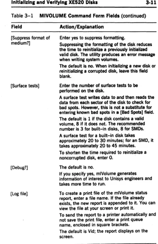
[Suppress format of medium?]
[image:34.399.50.363.28.510.2][Surface tests]
[Debug?]
[Log file]
Enter yes to suppress formatting.
Suppressing the formatting of the disk reduces the time to reinitialize a previously initialized valid disk. The utility produces an error message when writing system volumes.
The default is no. When initializing a new disk or reinitializing a corrupted disk, leave this field blank.
Enter the number of surface tests to be performed on the disk.
A surface test writes data to and then reads the data from each sector of the disk to check for bad spots. However, this is not a substitute for entering known bad spots in a [Bad Spots] field. The default is 1 if the disk contains a valid volume, 8 if it does not. The recommended number is 3 for built-in disks, 8 for SMOs. A surface test for a built-in disk takes
approximately 20 to 30 minutes; for an SMD, it takes approximately 20 to 45 minutes.
To shorten the time required to reinitialize a noncorrupted disk, enter O. . The default is no.
If you specify yes, mlVolume generates information of interest to Unisys engineers and takes more time to run.
To create a print file of the mlVolume status report, enter a file name. If the file already exists, the new report is appended to it. You can view the file at your screen or print it.
To send the report to a printer automatically and not save the print file, enter a print queue name, enclosed in square brackets.
3-12 Initializing and Verifying XE520 Disks
Table 3-1 MIVOLUME Command Form Fields (continued) Field Action/Explanation
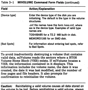
[image:35.398.36.335.50.353.2][Device type] Enter the device type of the disk you are initializing. The default is the type in the volume structures .
[Bad Spots]
. cnf file names have the form Ivxxx.cnf, where xxx is the device type. Examples of valid type names are:
TOSHIBA85 for a 12.2 MB built-in disk. MEMOREX166 for an SMD disk.
For information about entering bad spots, refer to Bad Spots.
To avoid inadvertently destroying a volume that contains valid data, mIVolume reads the sectors where a BTOS Volume Home Block (VHB) exists. If mIVolume locates a VHB, the information contained in it displays~ This information includes the volume name, the date it was created, the date it was last modified,and the number of free pages and file headers. It also prompts for
confirmation to reinitialize the volume.
Caution: Reinitializing a valid volume causes all data stored on the volume to be lost. Before reinitializing a valid volume, always back up any files that should be saved.
If you confirm the reinitialization and the old volume has a password, the system prompts you to supply the password. mIVolume echoes a: pound sign (#) for each password character you enter.· You press RETURN to terminate the password.
After listing the bad spots, mIVolume writes the volume control structures on the disk. The volume control structures include: the files Mfd.sys, FileHeaders.sys, BadBlk.sys, and DiagTest.sys; the Volume Home Block; and the Allocation Bit Map.
Note: The DiagTest.sys file is reserved for diagnostics. You cannot delete it and should not use it to store data. It is not backed up during a backup operation.
The DiagTest.sys file is allocated on the second-to-Iast track of each XE520 disk.
Finally, mIVolume creates the system files Syslmage.sys and CrashDump.sys. These two files are needed if the volume is to contain a master operating system (that is, the XE520 could boot from the volume). However, nothing is written to these two files at this time.
Guidelines for Initializing a Volume
The following is a list of guidelines for using the mIVolume utility:
D mIVolume does not allow you to initialize a volume
currently in use.
D If you are initializing a disk for the first time, you must enter the bad spots listed in the manufacturer's report that accompanies each disk.
For more information on how to enter bad spots, refer to Entering Bad Spots.
D Once you initialize a volume, you use the BAD SPOT
REPORT command to create a record of bad spots. You should save this record; you must have it if the volume
becomes corrupted. .
You can use the information the BAD SPOT REPORT command generates to create a file whose name you can enter in a [Bad spot] field of the MIVOLUME command
form.. You then need not enter each bad spot individually. Refer to Entering Bad Spots ..
o If you try to initialize a corrupted disk (that is, a disk the system cannot mount), you must enter all known bad spots.
3·14 Initializing and Verifying XE520 Disks
D If you are reinitializing a valid volume, you do not have
to specify the device type.
D If you interrupt the initialization operation, the volume
becomes invalid and you must reinitialize the disk as a new disk.
D If you are reinitializing a valid BTOS volume, you can suppress the medium formatting operation by
specifying yes in the [Suppress format of medium?] field. This reduces the time required to initialize the disk.
D The value specified for the maximum number of
directories is rounded up to the nearest multiple of 15 to produce the size of the file [sys] <sys> Mfd.sys. Since you can expand this file only by reinitializing the disk, it is important to determine an appropriate value.
D mIVolume allocates File Header Block (FHB) sectors for each file. The value specified for the maximum number of files is multiplied by 1.5 to allow for a certain number of extension FHBs. This product is then rounded up to an even multiple of three times the number of sectors on each cylinder of the disk.
mIVolume locates these FHBs on the disk to ensure that the primary and secondary FHBs are located on
different cylinders, at different rotational positions, and (for system volumes) on different disk surfaces.
Since you can increase this number only by
reinitializing the disk, it is important to determine an appropriate value.
D The value specified for the maximum number of files in
the <sys> directory is rounded up to the nearest multiple of 14. Because system performance is degraded if the volume is a system volume and this directory is more than 80% full, you must allow for more files than you needed.
Bad Spots
If you are initializing a disk for the first time or are initializing a corrupted disk (that is, a disk no longer mountable by the system), you must enter a listing of known bad spots in the [Bad spots] field of the MIVOLUME command form.
Once you initialize a disk, the system maintains a coded list of the bad sectors in the file <sys> badblk.sys~
A sector is identified as defective (and therefore omitted from the Allocation Bit Map) for three reasons:
o
You specified a bad spot in the sector in the MIVOLUME command form.o Before initialization, the disk contained a valid BTOS volume and the sector was previously identified in the bad sector file as defective.
o The sector failed the surface tests of the mIVolume utility.
Identifying Bad Spots
You identify bad spots by their location on the disk. A disk location is designated by cylinder/head/sector or
cylinder/head/byte (a cylinder is sometimes referred to as a track).
Bad spot locations are designated by the format: c/h/#s or c/h/b/l
c is the cylinder number h is the head number s is the sector number b is the byte .number
1 is the length of the defect. You should always use the value 1 to specify the length of the defect.
3·16 Initializing and Verifying XE520 Disks
Listing Current Bad Spots
To get a listing of bad spots, you specify a log file or print file name in the MIVOLUME or BAD SPOT REPORT
command form when you use one of these utilities. (Refer to Executing the BAD SPOT REPORT Command.)
--The report these utilities generate includes a listing of the bad spots currently stored in the <sys> BadBlk.sys file. You can use this listing to create a file whose name you can enter in the [Bad spot] field instead of entering each bad spot individually. For more information, refer to Entering Bad Spots.
Entering Bad Spots
To enter bad spots in the MIVOLUME command form, you can enter each bad spot individually or enter the name of a file that contains a list of the bad spots.
To enter bad spots individually, you type each bad spot designation in one of the form's three [Bad spots) fields. Do not break an individual bad spot entry over two fields.
If all the entries do not fit in the three fields, you must use the BTOS Editor to create a file that lists the bad spots, separating the bad spot designations by a space or carriage return. Then, in one [Bad spots] field, enter
@BadSpotFile, where BadSpotFile is the file you have listed the bad spots in.
To create a bad spot file, use the following procedure: 1 Copy the print file to the file you enter in a [Bad spot]
field.
2 Use the BTOS Editor to delete all nonpertinent information from the print file.
The only information to keep in this file is the bad spot listing itself.
3 In the [Bad spot] field, enter @BadSpotFile, where BadSpotFile is the name of the file you edited.
Note: If you are executing mlVolume through a
eLi
runstatement and are listing bad spots individually, you must enclose the list of bad spot entries in parentheses.
Note About Bad Spots
Built-in disk drives are formatted for 591 bytes per sector (512 of which are for data), 16 sectors (0-15), 7 heads (0-6), and 645 cylinders (0-644). You cannot enter a defect on a cylinder greater than 644 or having a byte value greater than 9455. Also, you do not enter bad spots for cylinder 644, head 6; it is the last track on the disk and
is
reserved. You should ignore bad spot information in the form degree n.Executing the BAD SPOT REPORT
Command
The BAD SPOT REPORT command invokes a utility that tests XE520 built-in and SMD disks for soft and hard errors without destroying valid data.
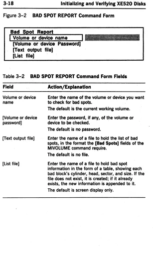
To use the Bad Spot Report utility, you enter BAD SPOT REPORT at the Executive command line. The system displays the BAD SPOT REPORT command form shown in figure 3-2.
3-18 Initializing and Verifying XE520 "Disks
Figure 3-2 BAD SPOT REPORT Command Form
Bad Spot Report
I
Volume or device name [Volume or device Password) [Text output file)[List file]
Table 3-2 BAD SPOT REPORT Command Form Fields
Field Action/Explanation
Volume or device name
[Votume or device password] [Text output file]
[list file]
Enter the name of the volume or device you want to check for bad spots.
The default is the current working volume. Enter the password, if any, of the volume or device to be checked.
The default is no password.
Enter the name of a file to hold the Jist of bad spots, in the format the [Bad Spots] fields of the MIVOlUME command require.
The default is no file.
Reducing Fragmentation with the
mDisk Squash Utility
To reduce volume fragmentation, you can execute the mDisk Squash utility on an XE520 disk. This utility consolidates multiple free areas on a disk into a single disk-extent free area. The analysis option allows you to determine the current state of a disk.
This utility does not consolidate all multiple-extent files into single-extent files, only free areas. To consolidate all multiple-extent files into single-extent files, you must back up, reinitialize, and restore the disk. Refer to section 6 for instructions on backing up and restoring a disk .
. Executing the MDISK SQUASH Command
Note: You cannot execute the mDisk Squash utility on any disk that has open files. If you attempt to execute the utility on a disk with open files, it aborts and returns an appropriate message. Therefore, before squashing a disk, you must make sure that no one is currently using it and that no files are open. Because the Command Line Interpreter (eLi) always keeps an open file on the system disk, you must perform the procedure outlined in
Preparing the System Disk for a Disk Squash before attempting to squash it.
To execute the MDISK SQUASH command on a disk other than the system disk, use the following procedure:
1 Enter MDISK SQUASH at the Executive command line. 2 Press RETURN.
The system displays the MDISK SQUASH command form shown in figure 3-3. Table 3-3 lists the fields in the MDISK SQUASH command.
3 Enter the device or volume name of the disk you want to squash in the Volume or device name field.
3·20 Initializing and Verifying XE520 Disks
5 Choose one of the following:
o Leave the [Analyze only?] field blank to squash the disk and receive the analysis report.
o
Enter yes in the [Analyze only?] field to receive an analysis report only and not squash the disk. 6 Choose one of the following options:o Enter a file name in the [Print file] field to obtain a file of the report.
o Enter a print queue name enclosed in square brackets to print out the report automatically without creating a print file.
Note: If your system has only one disk, you cannot use this option.
7 Press GO when you have filled in the appropriate fields of the command form.
Figure 3-3 MDISK SQUASH Command Form
mDlsk Squash
I
Volume or device name Il.l_~ [Volume password]Table 3-3 MDISK SQUASH Command Form Fields Field Action/Explanation
Volume or device name
[Volume password] [Analyze only?]
[Log file]
Enter the name of the volume or of the disk device to be squashed.
Enter the volume password, if one exists. To squash the disk and receive the analysis report, leave this field blank.
To receive an analysis report only and not squash the disk, enter yes.
Enter the name of the file you want the report written to.
Specify a print queue, enclosed in square brackets, to have the listing copied to a temporary print file and sent to the specified print queue.
If you do not name a print file or print queue, the system sends the information to the screen. If you have only one disk in your system, you cannot use this option.
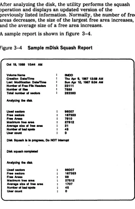
The utility first displays general information about the volume, including the volume name, when it was created, the last time data on it was modified, the number of free file headers, the number of files, and the size in sectors (512 bytes). The utility then analyzes the disk and returns the following information:
o
the number of used sectorso
the number of free sectors o the number of free areaso the maximum free area (the size of the largest free area)
o the average size of all the free areas o the number of bad spots
3·22 Initializing and Verifying XE520 Disks After analyzing the disk, the utility performs the squash operation and displays an updated version of the
previously listed information. Normally, the number of free areas decreas_es, the size of the largest free area increases, and the average size of a free area increases.
A sample report is shown in figure 3-4.
Figure 3-4 Sample mDisk Squash Report
Oct 18. 1888 1Cbt4 AM
Volume Name
CrHlJon O • .mme Lut ModHIcalIon Oar.mme Number of F,.. F . . . Nunmerof fUel
Teal number of MCtort
UHd MCtoIa
F' . . . cn
. F, . . ArMs
Mulrnum ".. .,.. Aver • • Ize of free . . .
Number of bIId . . . .
U . . count
SM)O
lhu • I. 1887 12:58 AM
Sun Ap 12. 1887 1:04 AM
22111 7888 283380 18007 187353 7110 27&12 21 -'5 o
Ollk Squuh It In prag .... Do NOT Interrupt
UHd MCtoIa
FIN HCtcn
F, . . Ar ... Mulrralm f, . . .,..
Aver. slz. of Ir . . ., . .
Number of bIId . . . .
U.., count
[image:45.398.29.309.44.477.2]