RESEARCH ON THE INVERSE KINEMATICS FOR 5R
MANIPULATOR AND ITS IMPLEMENTATION BASED ON
FPGA
1HU XINYU, 2ZHANG DAODE, 3YANG GUANGYOU, 4WANG QIANG 1
School of Mechanical Engineering, Hubei University of Technology, Wuhan, China E-mail: [email protected]
ABSTRACT
Analyzing the inverse kinematics theory and its solution method for 5R series manipulator, introducing the establishment of link coordinate system and D_H parameters for 5R series manipulator, studying the algorithm of inverse kinematics solutions based on FPGA controller for 5R manipulator, the system constructs the SOPC system architecture that is based on the Nios II CPU, uses the C program to compile the inverse kinematics solving module and adopts the Robotics Toolbox to simulate the inverse kinematics theory. The results show that the algorithm is effective to realize the inverse solutions of kinematics for 5R serial manipulator with FPGA.
Keywords: Series Manipulator; FPGA; Inverse Kinematics; Link Coordinate System
1. INTRODUCTION
The kinematics theory analysis of series manipulator is the study of motion relationships of the coordinates on the mechanical arm, which is the most basic content. The content of manipulator kinematics is included in forward kinematics and inverse kinematics, but to solve the problem of inverse kinematics theory is one of the most important contents of manipulator technologies [1], it directly affects the algorithms of the inverse solution’s optimization module and trajectory planning module that system follows. The inverse kinematics solutions of series manipulator is a process that makes the position and posture of end-effector in manipulator’s Cartesian space converted into each joint variable of the joint space[2].
There are a lot of inverse kinematics’ methods of solving for series manipulator, including the analytic method or method of algebra, geometry, spinor method, iterative method, neural network method, dual matrix method and dual four element method and so on[3]-[4]. Each method has different characteristics, some methods of solving have a small amount of calculation, whose real-time performance is very good, but can only get local solution; and other methods with a large amount of calculation is not suitable for real-time applications. In the 5R series manipulator system, we use the closed analytic method to solve inverse kinematics equations and the method has the advantages of fast
computation, high efficiency and convenience for real-time control.
The paper makes theoretical analysis and implementation based on four parts of the content, which are the establishment of pole coordinate system, the theoretical analysis and inverse kinematics solutions, the realization of inverse kinematics solutions of FPGA and the inverse kinematics simulations based on Robotics Toolbox .
2. ESTABLISHMENT OF LINK
COORDINATE SYSTEM AND DEFINITION OF D_H PARAMETERS
1) Zi coordinates axis along the axis direction of i+1 joint;
2) Xi coordinates axis along a common vertical line of the Zi and Zi-1, and points the direction away from the axis Zi-1;
3) The direction of Yi coordinate axis should meet the requirement: the shaft Yi, the shaft Xi and the shaft Zi can make the right-handed Cartesian coordinate.
The coordinate system of 5R manipulator established by the system and its structure diagram as shown in Figure1, the fixed coordinate system
{ }
O0 is set up in robot base(base),0 0
O X stands manipulator’s front, O Y0 0 stands manipulator’s transverse direction, O Z0 0 stands the longitudinal direction of manipulator (body),
O X
1 1is in a horizontal plane,
O X
2 2 is along the axial direction of big arm,O X
3 3 is vertical to the small arm axis, O X3 3 ⊥O X4 4, the origins of coordinates O3 and O4 do not coincide, O X Y Z5 5 5 5 is the terminal coordinates (hand).Determine D-H parameters in each joint of the manipulator on the basis of establishing a proper link coordinate system as follows in Table1, the table includes 4 parameters: connecting angle
θ
i, connecting rod offsetd
i, length of connecting rodi
a
and link twist angleα
i, the two parametersi
a
andα
i describe the characteristics of size of thelink, and the two parameters
d
i andθ
i describethe relative positional relationship between the connecting rod. In addition to the variables that the joint corresponds to, the other parameters are decided by the mechanical attributes of a connecting rod ,and is relevant to link coordinate system, but do not change with the joint motion.
Table1. D-H Parameters Of Joint Manipulator
3. THEORETICAL ANALYSIS AND SOLUTION OF INVERSE KINEMATICS
The inverse solution problem of manipulator’s kinematics refers that in the case of knowing the target pose that the robot end-effector (hand) should reach, through the coordinate inversion to calculate the various joint variable’s translational and rotational value, to drive the joint’s servo or stepper motor to rotate, so that the hand pose is satisfied, this is the manipulator’s inverse kinematics problem[6]. The mapping from the manipulator’s joint space to the end of the Cartesian space is a single shot, that is a mapping relationship of one to one or more to one; however the mapping from end-effector Cartesian space of the industrial robot to the joint space is a kind of complex mapping relations, namely a one-to-many mapping relation.
The forward kinematics of series manipulator describes the mapping relationship and coordinate transform from the joint space to the end of the Cartesian space; the inverse kinematics of series manipulator describes the mapping relationship and coordinate transform from the end of the Cartesian space to the joint space. In control of series manipulator, the inverse kinematics is used to control the position of robot manipulators in Cartesian space, and the characteristics of inverse kinematics’ solutions include: the solution may not exist, the uniqueness of the solution and the diversity of the method for solving and so on [7]-[8]. Industrial manipulators have a certain scope of
work; different manipulators have different scope of work, which is decided by the hardware structure. When the object is placed out of the working range of the end operator, we cannot calculate the inverse solution of
[
θ1 θ2 θ3 θ4 θ5]
; the inverse kinematics of industrial manipulator may have multiple solutions, because in solving inverse trigonometric function equation, sometimes positive and negative cases may appear at the same time. In general, one of the solutions is not accord with the real manipulator’s movement status, which will be removed. Finally, we will make optimum selection according to the actual constraint conditions , including the shortest path, shortest, fastest and most stable trajectory and so on; there are lots of methods of solving of inverse kinematics of industrial manipulator, typically using analytic method and projection method, analytic method is the algebraic method and projection method is geometric method, we should strive to be obtained closed-form solution, because the closed solution has the advantages of fast computation, high efficiency and convenience for real-time control.The inverse kinematics equations of manipulator in system with 5 degrees of freedom are solved by using the closed analytic method, because the calculation process is very complicated, this thesis ellipsis them and directly gives calculation results. The kinematics posture matrix of Cartesian space is known as formula (1):
50
n
o
a
p
n
o
a
p
=
n
o
a
p
0
0
0
1
x x x x
y y y y
z z z z
T
(1)And
T
50=
T T T T T
1 2 3 4 5,1
T
, 2T
, 3T
, 4T
and 5T
is unknown matrix, the value of the 5 matrix are about 4 parameters: length of connecting rod ai, link twist angle αi, connecting rod offset di and connecting angle θi, ai,αi and di can be known from D-H parameters. Therefore, the posture matrix of1
T
,T
2,T
3,T
4andT
5 can be calculated, its unknown elements are about the trigonometric function of θ, namely they are obtained through solving inverse solutions. The posture matrixes of1
T
, 2T
, 3T
, 4T
andT
5 are respectively formula (2), formula (3), formula (4), formula (5) and formula (6) as follows:1 1
1 1
1
cos 0 - sin 0 sin 0 cos 0 =
0 -1 0 0 0 0 0 1
T θ θ θ θ
(2)2 2 2 2
2 2 2 2
2
cos - sin 0 a cos sin cos 0 a sin =
0 0 1 0 0 0 0 1
T
θ θ θ
θ θ θ
(3)3 3 3 3
3 3 3 3
3
cos - sin 0 a cos sin cos 0 a sin =
0 0 1 0 0 0 0 1
T
θ θ θ
θ θ θ
(4)4 4 4 4
4 4 4 4
4
cos 0 - sin a cos
sin 0 cos a sin =
0 -1 0 0
0 0 0 1
T
θ θ θ
θ θ θ
(5) 5 5 5 5 5 5cos
- sin
0
0
sin
cos
0
0
=
0
0
1
d
0
0
0
1
T
θ
θ
θ
θ
(6)The solving process of inverse kinematics equations as follows:
1)To calculate θ1. -1
1 50= 2 3 4 5
T T T T T T will be
obtained through multiplying T1-1 at both sides of
50= 1 2 3 4 5
T T T T T T at the same time, spread out both sides of the equation respectively, elements in third rows and fourth columns of the two matrix are equal, formula (7) can be got:
1 1
s c =0
x y
p
θ
pθ
− + (7)
Setting: x
y
p = cos
p = sin
ρ ϕ
ρ ϕ
(8)In the
stands the arctangent value of y
x
p p
, substitute in
formula (8), get the formula (9):
(
1)
sin ϕ θ− =0 (9)
The
θ
1can be got by the formula (10):(
)
1
= =arctan2
,
=arctan
y y x x
p
p
p
p
θ ϕ
(10)
2) To calculate
θ
5. Through formula:-1
1 50= 2 3 4 5
T T T T T T , the formula (11) can be got:
(
)
(
)
5 1 1 5 1 1
11.1
11.2
s = n s +n c = o s +o c
x y
x y
c
θ θ θ
θ θ θ
− −
− −
(11)Then
θ
5 can be obtained through the formulaof
(
)
(
)
11.1 11.2
:
n s n c
1 1
=arctan
5 o s o c
1 1 x y x y θ θ θ θ θ − −
(12)3) To calculate
θ
2 .T T T
2-1 1-1 50=
T T T
3 4 5 can be obtained through multiplyingT
2-1 at both sides of-1
1 50
=
2 3 4 5T T
T T T T
, finally the result ofθ
2 is the formula (13):2
2 2 2
m k
=arctan +arctan
n m n k
θ
± + −
(13)
4) To calculate
θ
3. Finally the result ofθ
3 is the formula (14):(
)
(
2)
2 4 1(
1 5 z)
3 2
1 1 2 2 4 z 5 1 1
p a s +a a c +a s d a
= +arctan
p c +p s a c +a a d a c +a s
z x y
x y x y
θ θ θ
θ θ
θ θ θ θ θ
− − −
−
− −
5) To calculateθ4. Finally the result of θ4 is the formula (15):
1 2 1 2 2
4 3
1 2 1 2 2
a c c +a s c a s = +arctan
a c +a s +a c
x y z
x s y s z
θ θ θ θ θ
θ θ
θ θ θ θ θ
−
− (15)
What tells above is the solving process of inverse kinematics,
θ
1 ,θ
2
θ
5 will be calculated by solving the inverse trigonometric function equation.There are 8 groups of solutions of the inverse kinematics for 5R manipulator, however, due to the actual constraint of the manipulator, some solutions are not in the end effector domain, and so last movement of 5R manipulator should be decided according to the real situation and optimization choice.
4. IMPLEMENT OF INVERSE
KINEMATICS SOLUTIONS OF SERIES MANIPULATOR BY FPGA
Because the inverse kinematics solutions of 5R series manipulator have been obtained, now we can achieve the inverse solutions (θ1, θ2, θ3, θ4, θ5) of manipulator by use of FPGA controller. Using FPGA as the hardware platform to achieve has two ways:
1)To complete the algorithm of inverse kinematics) based on the Verilog HDL hardware description language, to achieve the inverse trigonometric function’s solutions by using a very important CORDIC (Coordinate Rotation Digital Computer) [9] technology, the operation process of complex inverse trigonometric function in mathematics is solved by using FPGA hardware logics.
2)To complete the algorithm of inverse kinematics in Nios soft processor based on the C language, using a SOPC (System on a Programmable Chip)[10] technology to achieve the inverse trigonometric function solutions, the system uses programmable technology in SOPC on-chip to achieve the algorithm of inverse kinematics of 5R series manipulator.
The development of SOPC system includes the hardware part and software part, the hardware part’s development is adopted by SOPC Builder software that uses Quartus Ⅱintegrated development environment, and the software is developed by Nios
inverse kinematics solutions here are many groups of solutions, and we should select a group of optimal solutions from the optimization module of multiple solutions.
5. INVERSE KINEMATICS SIMULATIONS OF SERIES MANIPULATOR BASED ON ROBOTICS TOOLBOX
For control systems of 5R series manipulator, the simulation of its model is crucial. Because of many contents of the manipulator are related to analysis and verifications obtained by using different simulation software to achieve simulation process, including the forward kinematics of the manipulator, inverse kinematics of the manipulator, workspace and the plan of its trajectory and so on. System uses Robotics Toolbox robot toolbox to achieve the simulation and verification of inverse kinematics of the manipulator. In order to conveniently explain, the main inverse kinematics simulation program of Matlab is as in Figure 3, the inverse solution is solved by calling the function Ikine in the program, after running the program above a group of joint angle of Q1 will be seek out, when Q1 and Q are the same, the results of simulation are entirely correct. Q1 = [0 1.5708 0 1.5708 0] by Matlab simulation and q = [0 pi/2 0 -pi/2 0] are exactly same, the results of simulation are entirely correct. At the same time, the calculated Q1 are also validated to be similar with the joint angle obtained by theoretical analysis.
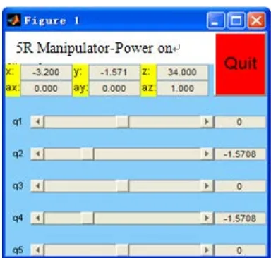
The sliding control box of 5R manipulator will be popup after calling the Drivebot function, as shown in Figure 4, the consistency of theory and simulation is also proved by these data.
Figure 4. Sliding Control Box Of 5R Manipulator
6. CONCLUSION
[image:5.612.323.515.304.487.2]Inverse kinematics theory of 5R series manipulator and regarding FPGA controller as the hardware platform in its application of solving algorithm have strong reconfigurable hardware advantages, we can build a SOPC system, use Nios soft core processor and C language to achieve real-time control, and can be combined with the module of Verilog HDL language to complete the development of the solving of inverse kinematics, shorten the cycle of the development. The establishment and D_H parameters of link coordinate system of 5R series manipulator have been introduced, to achieve the solution of inverse kinematics equation by using the closed analytic method in the 5R series manipulator system, the method has the advantages of fast computation,
Figure 2. Joint Angle Values Obtained By The Solving Of Inverse Kinematics Based On SOPC
System Manipulator
high efficiency and convenience for real-time control. The paper puts forward a design proposal of using SOPC system to complete the inverse kinematics solution of the manipulator. Through the experimental test and simulation, the inverse kinematics theory of 5R series manipulator based on FPGA and its validity and reliability are tested and verified. The conclusion will be regarded as the foundation of the follow-up work for algorithm module that includes inverse optimization and path planning in the 5R series manipulator.
ACKNOWLEDGEMENT
This work is supported by National Natural Science Foundation of China (No.51174084 and No.51275158), Natural Science Foundation of Hubei Province (No.2012FFB00604 and No.2010CBB00801), the Education Department Project of Hubei Province (Q20121408) and Wuhan Chenguang Project of the Youth Science and Technology (No. 201150431128).
REFERENCES:
[1] Paul R.P., Shimano B., Mayer G. E., “Kinematics control equations for simple manipulators”, IEEE Transactions on Systems, Man and Cybernetics, Vol.11, No.6, 1981, pp. 449-455.
[2] Jian Xie .Wenyi Qiang, Bin Liang, Cheng Li, “Inverse kinematics problem for 6-DOF space manipulator based on the theory of screws”,
Proceedings of 2007 IEEE International Conference on Robotics and Biomimetics, ROBIO, Sanya, 2007, pp.1659-1663.
[3] Liegeois A., “Automatic supervisory control of the configuration and behavior of multibody mechanisms”, IEEE Transactions on Systems, Man and Cybernetics, Vol.7, No.12, 1997, pp.868-871.
[4] Novakovic Z.R., Nemec B., “Solution of the inverse kinematics problem using the sliding mode”, IEEE Transactions on Robotics and Automation, Vol.6 , No.2, 1990, pp.247-252.
[5] Chan T. F., Dubey R. V., “Weighted least-norm solution based scheme for avoiding joint limits for redundant manipulators”,
Proceedings of IEEE International Conference on Robotics and Automation, Atlanta, 1993, Vol.3, pp.395-402.
[6] Kohli D., Osvatic M., “Inverse kinematics of general 6R and 5R, P serial manipulators”,
Journal of Mechanical Design, Transactions of the ASME, Vol.115, No.4, 1993, pp. 922-931.
[7] Wang L. T., Chen C. C., “A Combined Optimization Method for Solving the Inverse Kinematics Problem of Mechanical Manipulators”, IEEE Transactions on Robotics and Automation, Vol.7, No.4, 1991, pp.489-499.
[8] Khairudin M., Mohamed Z., Husain A.R., “Dynamic model and robust control of flexible link robot manipulator”, Telkomnika, Vol.9, No.2, 2011, pp.279-286.
[9] Considine Vincent, “CORDIC Trigonometric Function Generator for DSP”, Proceedings of IEEE International Conference on Acoustics, Speech and Signal Processing, Glasgow, Vol.4, 1989, pp. 2381-2384.
[10] Corke P.I., “Robotics Toolbox for MATLAB”,
IEEE Robotics and Automation Magazine, Vol. 3, No. 1, 1996, pp.24-32.