·
mnmnoma
1971
·
;
..
Copyright 1970
Digital Equipment Corporation
FOREWORD
'The PDP-12 general purpose laboratory computer is a powerful partner to · research and developmental activities; especially for storing, collating, combining, arid analyzing laboratory data. it converses directly with the . laboratory 'user while experiments take place. It displays results in time for him to vary experimental sequences based upon emerging results, giving him the power for creative problem solving, not mere data shuffling.
The laboratory ·user also gets long-term instrumentation economy. Economy and the ability to change data instrumentation tasks withou~
changing the instrument. Economy in the ability to expand (including the size of the computer) by adding modules or options. ·
Ther~ is an investment to be made. Several weeks of diligent study of
COrtJPUter fundamentals ta s~art. But, the payoff is great. Dividends come i.n terms of an entire career, and adding the computer discipline to your own, and the ability to do more and better laboratory work.
.
'·Digital Equipment Corporation has played a pioneering role in developing all purpose computers, particularly suited for the laboratory environment. Thousands of DEC computers are being used at universities, research and Etevelopment centers, industry, pure and applied research, and physical, life, and behavioral sciences. ·
With development of the PDP-12, DEC has combined the features of three successful general purpose computers - the LINC, developed under r,.ational Institutes of Health and NASA grants, ·the popular PDP·8, and the LINC-8, into a single, complete data handling facility.·
The PDP·l2, described in this handbook, has become a standard in its --field. It is the most modern of a family of 12-bit machines, designed Spe(tifically for the laboratory market place. It has the capability of utilizing programs written for the LINC, PDP·8, and LINC-8 with relatively minor modification.
•
Today's graduating engineer, scieotist, and technician will encounter the
INTRODUCTION
INTRODUCTION TO LABORATORY COMPUTERS
Until approximately 1963-1964, the concept of having a computer for use by researchers within the laboratory environment was almost unheard of,. except in very special cases. Both the physical size and the price-' of such equipment was awesome, and it was highly unlikely that a single researcher, or small group of researchers could put forth a strong enough argument to justify the purchase of equipment that would cost several hundred thousand dollars. At that time, there was very little available. if any, that had the characteristics so necessary of a laboratory environ· ment which is the requirement for "hands-on, on-line, interactive com-puting capability."
The use of a computer in a laboratory, represented a unique departure from the classical use of most computational equipment. In most cases, data from experiments was acquired off-line and then prepared for entry to the computer, typically via punched cards, paper tapes, or digital magnetic tapes. When time 011 a central computer was available, the data was analyzed by programs that had previously been prepared and finally the results of the experiment were available to the researcher. Typically, the "turnaround'' time was at best several hours, and at worst several days. The use of the computer for the researcher was beginning to prove a valuable tool .in the data reduction and analysis of his work, but the time required to give him the all important "feedback" ab6u,t his experiment was still much too long. The optimum situation would be where the computer could be integrated into the experimental setup and _the data could be acquired on-line and analyzed in the laboratory, and eventually feed back and control the experimental setup. ·
One of the early projects aimed at developing such a computer was the LINC program. LINC was a pseudonym for a Laboratory /Nstrument Computer and was designed primarily to fulfill the needs of the life and physical sciences research.er. The initial designs were aimed at fulfilling the following requirements:
1. Ease of interface to standard laboratory instrumentation, which included both analog and digital signals.
2. CRT ,display - for both graphical and numerical data display and results.
3~ Auxiliary storage - for rapid access to both programs and data.
4. Ease of use - such that semi-skilled laboratory technicians could operate the equipment and run the experiments.
The fulfillment of these requirements together with improvements in the state of the art, and price/performance ratios were embodied in the LINC, UNC-8, and eventually the PDP-12 as manufactured by Digital Equipment Corporation. The present PDP-12 represents the third genera-· tion of this laboratory computer concept. As of mid-1970 there are over 600 such machines in use throughout the world in numerous laboratory environments.
s
.,,
0,,
...
N.,,
""o
C-OQ :J . ,(') I»
~3 0 :J
3
!!.. ~ ~o 0 I» n .. ,... I» 0 .,,-·.,
I» 0 OQ (')
D1 ~
3
.,
~i
CD3
&SR TTY READER NID
PUHCH
\/Rl2
DISPlAY
lllJlTll'\.DER
~TO 1 - -- - -32CHAMELS
16 AllOITIONAL PMMIPS #012 TU5!i lruOR~I 1\r.15 i.>TO 8
-ntAHSPOfITS DIGITAL PLOTTER -I I IBASIC POP·l2
VCl2
DISfoL.tlY IXllfTROL
A012 16 CHAHNEL AID CON\1£f1T£R
-llOJL~IPLEXER
01112 S~4Wf, .. E
RELA'IS
TCIZ LINCTAl'E OONT'llOL
TCIZ·F U•CTAP£1DECTAP£
-TA81LITY KE12 AlllOMATIC POP-I
llOJLTIPLY I OIVUlf:
KWl2
AEAL TIME CL00c
XYl2 PLC1fTER CONTllOL
AOOITIClNAL
-·
I
-~12
~NSIOfOI
4KI
r
~·~'°""'-Wit AOOITIONAL 4K OP12 TTYIOATA-INn:RFACE
TO o.m llll£AI<
POSIT'Nt D&lll BREAK Mell.ITT
-POSITlllE 1/0 11US
0Wo8A 1/0 AND Ol<tA
1REA11 COIM:RTElt
UP TO 50' TOTAL LENGTH
<»'WKN-AOOEJll DC1ZE
~
MULTIPLE UPTO LiNfS- -8A!2l'ERIPHEllAl
El<l'l\NOOI
t,';li PRINTER
§
- 2 - lllPE llEADet PP12 IW'ER 1llPI!: l'l1'CH PC12 - T -REMlEllmJNCH a.12CM011£AD01I
UPT02:2~1 T~
CONTROL
TU22, TU25 Oft l\.128
NEBATIVE 1/0 etis
DM01
~
MULTIPL£l!fR
AFOtA DIA QONVEl!l'ER
-MULTIPLIER
AAOS AA01
DIA CONV£RTER ,
°"'
CONV£RTEll~
E~~
P'M:IUTY '-~~~~~~~UP TO S DF32 DISC TC51 MM TAP( CxwrllOLLEll TU20~ RFOI DISC CQNTllOU.ER
&
UPTD32K l'Oif£RIFAJL
-RIESTAAT ___ EXPANDER
UP TO I
TllAN8l'OlltS UP TO 4 DISKS
0-TTY OR llDOEM-HOW THE PDP-12 FULFILLS THE LABORATORY REQUIREMENTS
Inherent in the definition of a laboratory computer system is the term "flexibility". It is man9atory that the user isn't required to change his instrumentation, but rather only experimental conditions. In this respect the laboratory computer as a laboratory instrument is quite unique. Its 'general purpose nature allows the user to reprogram it, handle a larger range of experimental conditions and environments without physical .chan~e to the hardware configuration.
"Flexibility" - .The PDP-12 includes within its single central processor two distinct operatfng modes, each with its own complete instruction set. Like its predecessor, the LINC-8, the PDP-12 operates in one mode as a LINC (laboratory INstrument Computer) and in the other mode as a
PDP-8 computer - specifically a PDP-8/1. Both operating modes have
equal status, and the computer may be stopped and started in either mode, and the programs may switch from one mode to the other at will. Computations in one mbde are immediately available to programs operat~ ing in the other mode, plus only one set of processor registers are involved.
The basic memory capacity of the PDP-12 is 4096 (4K) 12 bit words and
can be expanded to 32, 768 (32K) words of 1.6 µsecond core storage.
The in~ut/output facilities are available to the two operating modes of the PDP-12 in the following manner through LINC mode programming:
LINCtape - two tape transports controlled by a buffered subprocessor.
CRT Display - 6" x 9" screen, two intensification channels.
Analog Inputs - eight variable potentiometers, eight external· inputs,
·expandable to 24.
Relay Buffer - six relays for control of external equipment.
In addition to these, the PDP~12 is also equipped with a positive logic
-PDP-8/1 type input/output (1/0) bus, to which can be attached, all PDP-8 peripherals and options such as a .high-speed paper tape reader
and punch, as well as the standard ASR-33 Teletype.
Central Processor
The central processor contains all the logic and registers required to carry out the functions of both operating modes of the PDP-12. The central processor can best be described in terms of its active registers:
·Accumulator (AC) 12 Bits - This register contains data being operated
upon. Its contents may be shifted or rotated right or left; incremented,
cleared, or complemented; .stored in memory or added to the contents of
a memory register; and logically or arithmetically compared with the con-tents of any memory register. The AC holds the sum after an addition, and part of the product after a multiplication. The AC is also involved in the transfer of data to and from various other registers outside the central processor.
.
. . .Link (L) 1 Bit - The Link is an extension of the AC. When a carry occurs
may be included (or not) in shifting and rotating operations performed on the contents of the AC.
Multiplier Quotient (MQ) 12 Bits - This register is used as a second
arithmetic register for multiply and some rotate instructions. It is also
used for the extended Arithmetic Option (KE 12) functions. ·
Program Counter (PC) 12 Bits - . This register contains the address of
the n·ext instruction to be executed within the memory field selected by
the .Instruction Field Register (see below). In PDP-8 mode, the PC acts
as a 12-bit coun~er; in LINC mode, itactS as a 10-bit counter.
Memory Address Register (MA)
12
Bits· - · This register contains theaddress for memory references. Whenever a core memory location is
being accessed, either for reading or for writing, the MA contains the
J
address of that location.
Instruction Register (IR) 12 Bits - This register contains the complete
binary code of the instruction being executed.
Memory Buffer (MB) 12 Bits - All information passing between memory
and any other register in the PDP-12 must go through the Memory-Buffer
Register, whether the tra.nsfer involves the central processor, an external
device, or another memory register.
Instruction Field Register (tf) 5 Bits - This register selects the memory
field containing the executable program. In LINC mode, it i,S ~sed to
designate one of up to thirty-two 1024-word segments. In PDP-8 mode, the three high-order bits of the IF are used to designate one of up to eight 4096-word fields.
Data Field Register (DF) Bits - This register selects the memory field
containing data to be indirectly accessed \by the memory reference in·
structions of a program. The. fields are specifi.ed in each mode in the
same way that the IF specifies the Instruction Field.
Memory
The principal unit of core memory is a module of 4096 (4K) 12-bit words. Additional 4K banks may be added, to a total of eight, or 32,768 words. Within each bank, the logical organization of memory depends on the operating mode. In LINC mode, the bank is divided into four 1024-word segments. At any given time, only two of these segments are active: the
.Instruction Field, which contains the executable program and the directly
accessed data; and the Data Field, which contains only indirectly accessed
data. Absolute addresses may be assigne~ and changed at will using the
IF and OF described above.
In the
PDP~a
mode, the memory field, which is the size of a 4K m'odute,'is divided into 32 pages of 128 words each. Within a single page, data
may be accessed .directly; between pages, indirect addressing must be
used. If more. than 4K of memory is provided, the IF and Of registers
Operating Modes
The two operating modes, LINC and.PDP-8, are independent of each other, though they may be combined and intermixed within a program. The user can run programs from the already-existing libraries for the PDP-8
family of computers .including the LINC-8. Using the 1-0 Handler
(PRO-GOFOP simulator) program provided with the PDP-12 basic software; most programs written for the LINC-8 can be run without modification. (Some
LINC-8 programs may. require slight changes). A complete so~are
sys-tem designed for PDP-12 allows the programmer to assemble coding for
either or both .modes in a single program.
LINC Mode - In this mode, the instruction set of the classic LINC com·
puter is implemented. -In addition, several new provisions are available:
-Extended
Tape Addressing - This allows the programmer to transfer information between LI NCtape and any section of core, removing the restriction to specific quarters of a given memory field. Other features"include:
l.
Tape Interrupt - which connects the tape processor status to .· the Program Interrupt.
·
2.
No-pause - which permits the central processor to resumeoperation after initiating a tape transfer without waiting for completion •
..
3.
Hold-motion -. which allows a unit to remain in motion afterdeselection.
1/0 Bus Access - In LINC mode the user has immediate access to those
devices actlv~ted by LINC instructions A·D, DISPLAY, RELAYS, SENSE
LINES, and TAPE. Any device connected to the 1/0 bus may be directly
access8d from LINC mode programming by· means of a special tWo-word
instruction,. in which the second word enables the bus and initiates the
. PDP·S IOT timing chain. This second word is interpreted as a standard
. PDP·S IOT instruction. The program continues to operate in LINC mode.
Special Functions - The LINC programmer may, by setting certain
fllp·fllops: 1) change the size of characters· displayed on the CRT; 2)
enable ·the program trap, which intercepts certain LINC instruction codes;
3) dfsab1e Interrupts from the ASR-33; 4) speed the sampling of analog
Jnp4tS; and
5)
clear the PDP-12 status by generating a~1/0
preset pulse.PDP.&
Mode - In this mode, the user has available the entire PDP·S/I 1.nstruction ·set •.lntenM:tlon Between Modes -.--The user may switch from one mode to the
other at will. In LINC mode, execution of the instruction PDP causes
th• processor to ct:iange immediately to PDP·8 mode operation, and all
subsequent instructions-are interpreted as PDP-8/1 instruction. To switch
from
PDP-8 mode to LINC mode the IOT instruction LINC is used.lnWlt/()utput
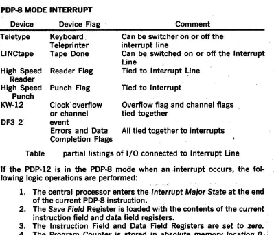
Facilities •nd DisplayAs ciln· be seen from Figure l·l, there are two inain paths for the
transmislon of data fr()m the central processor or memoi'y to. peripheral
devices. One path, which is controlled by LINC mode programming, leads to the CRT display, LINCtape, A-D converter, and relays. The other path,
which is the 1/0 bus, leads to the ASR-33 and to a large number
of
op-tional devices, such as: plotters, high-speed tape and card readers, disk storage, line printers, etc.
Display - The Cathode Ray Tube Display has a 58.5-square inch (6.5
x 9 inches) screen, on which individual points and whole characters may
.be displayed.· The unit has two intensification channels, controlled by
programming and by a switch on the dispiay. Characters are plotted on
a 4 point x 6 point matrix; a full character can be displayed with two ·
instructions. Provision is made for displaying two sizes of characters.
Data Terminal -The data terminal provides a flexible means of receiving analog inputs and controlling the operation of external equipment not directly interfaced to the PDP-12 .
. Analog Inputs - Sixteen analog inputs feed a 10-bit A·D converter. A
single LINC mode installation samples any of the 16 channels. A second set of sixteen inputs with preamplifiers, can be added to the basic facility.
Eight of the inputs, taken from phone jacks mounted on the Data Terminal Panel, are fed through preamptifiers to the converter. The remaining eight are taken from continuously-variable, ten-turn potentiometers, which
are also mounted on the panel. ·
Relay Buffer - Six relays, mounted on the Data Terminal Panel, may be
switched by means of a LINC mode iflstruction. The relays may be used
to start and stop operations in external equipment. The status of the
relays can be read back into the AC.
Auxiliary Scope Connector - A Blue Ribbon connector mounted on
the
Data Terminal Panel rs wired to accept an auxiliary CRT for displaying
information also sent to the screen of the built-in scope. ·
Sense Unes
These 12 digital sense lines may be individually ~sted with a LINC
mode instruction.
J,.INCtape - The tape transports are controlled by a fully-buffered tape
processor; once initiated by the UNC program, tape operations can be
carried out independently of the central processor. Tapes normally are
written and read in standard LINCtape format, tha1.~gh non-standard
formats can be used. A special hardware option, TC12F, permits the use of all DECtape formats. In addition to the basic LINCtape commands, the PDP-12 also includes an Extended Operations facility, which allows, among other features, the transmission of data between tape and any program-defined area of memory, and the addition of TU55 or TU56 transports to a total of eight tape drives.
Input/Output (1/0) Bus - This connecting facility provides the control
and data transmission path between the central processor and any
peri'pheral devices that are attached to the bus. For some devices, such ·
as: paper tape readers and punches, line printers, and incremental
magnetic tape and disk, use the three-cycle Data Break for direct memory
. access. The I
/0
bus uses positive logic and accepts peripherals usedwith 8 family of computers. The processor is prewired to accept the
following 1/0 bus options:
Extended Arithmetic Element(EAE), Type KE12
Programmable Real-time clock, Type KW12 A, B, or C
Incremental Plotter and control, Type XY12
TTY or Dataphone Interface, Type DP12
Many o~her devices can be added to the PDP-12 1/0 bus with the
inclu-sion of the BA12 Peripheral Exp~nder and the DW08 1/0 and Bus
Con-verter. The Peripheral Ex-pander allows the addition of high-speed paper
tape reader and punch, ca·rd reader, and optional communication inter·
faces. The Bus Converter provides for the addition of disk and IBM· compatible magnetic .tape storage, and A/D and D/A converters and
as$ociated multiplexers designed for the negative-logic PDP-8
1/0
Bus.Keyboard/Printer (ASR-33) -· An important means of direct
communi-cation between the user and the operating program is the ASR-33 Key·
board/Printer, standard on all configurations of the PDP·.12. The ASR·
33 is connected to the l/'O bus, and can be accessed for input or output
by programs in either operating mode. The ASR-33 is equipped with paper
t~pe reader and punch; the reader and keyboard use the.same input path and instructions, while the printer and punch use the same output patli
and instructions. The maximum transfer rate in either direction is
10
characters per second.
The ASR-33 has both full·. and half-duplex capability, In full-duplex
op-eration, data may be transmitted in both directions simultaneously,
with-out interference. In ha1f-duplex operation, data may· be transmitted in
Sy SAmplifying program tasks. the PCP·l2 frees users from the mechanics
of proaram preJ)ilration to concentrate on more cteative a5pect5 of their
wor1c.. •
LAB COMPUTER HANDBOOK
·
TABLE OF CONTENTS
/
FOREWARD ... 'HI · INTRODUCTION ... , .. .. . . .. . . .. . .. . . . .. . . .. .. ... . . .. .. .. . . .. . . .. .. .. . .. . . . .... . V
Introduction
to:
Laboratory Computers ... :... ... V How th~ PDP-12 Fulfillsthe
Laboratory Requirements.:... VI(CHAPTER
1
BIOMEDICAL SYSTEMSSignal. Averaging ... ·... ... .. .. .. .. . .. . . .... .. . .. . . .... . .. . .... . .. . .. ... 1
Time lnterv~I Histograms ... , ... , ... ,....
1
Signal Editing and Fr~que·ncy Analysis .. . ... ... ... .. . .. . . .. .. . . .. .. .. ...
12
.·CHAPTER
2
CHEMISTRY SYSTEMS. lntrod.ueti<;>n .. , ... : ... :...15
Hardware Description ... ~·: ... :... ... . . ... .. ... ... ... ... ...
16
Analytical Instrument Package . . .. . .. . . . .. .. .. .. .. . .. .. . .. .. .. . . . .. . .. .. .. . .. . . .. .
17 ·
.
.
Float\ng Point Processor ... :...19
System Effects of AIP and FPP ... ...
30
· Analytical lns~rument Package Operating System ... :... 31
Multi-Instrument Qata Acquisition System ... :... 31
'.Display-Oriented Research Analysis ,,... 32
· , .Matb .. Routines ... , .... : ... ·. 32
Specific Applications. Software ... ,... 33
CHAPTER 3' EDUCATIONAL SYSTEMS · Engineering Curriculum ....:_ w ;,. ... • ,... ; 35
, . Computers
tn
the School Laboratory ..... :.......... 37BASIC ... : ... !... 37
FORTRAN ... ·... 38
DIBOL ... : ... , ... ~ ... '. ... :... 38
FOCAL ... : .. ,. ... : ...•.. ·.. 3~
CHAPTER 4 INDUSTRIAL SYSTEMS
Analog Inputs ... ,... 70
Digital Inputs .. . .. . . . .. . .. . . .. . . .. . . .. . .. ... . . .. . . ... .. . .. 70
Real-Time Clocks . . . .. . . . .. . . .. ... . . .. .. . . .. .. ... . .. . . .. ... 71
Role of the Computer ... ·, .... .. .. .. .. . .. ... .. .. .. .. .. .. .. . .. .... 71
CHAPTER 5 CLINICAL LABORATORY SYSTEMS Introduction ... ·:.. ... .... . . .. . . .. .. . ... . . ... . .. . . . .. . ... . . .. . . .. . . .. . . .. . . . 79
Function.al Description ... : ... 79
.
.
Software ... : .... ·... 84Hardware ... 88
CHAPTER 6 PHYSICS APPLICATIONS A Basic Program for Pulse Height Analysis... 93
Constructing the Detailed Algorithm ... .'... 95
PHA-12 ... ·... 99
CHAPTER 7 REAL TIME CLOCK KW12-A Real Time Interface ... : ... 103
Clock Counter Register .. .. .. . .. .. . .. .. .. .. .. .. .. .. .. . .. .. . ... .. . .. .. .. .. .. .. .. . .. . 104
Buffer-Preset Register ... : ... 104
KW12-B a-nd KW12-C Fixed-Interval Clocks ... : ... 116
CHAPTER 8 PDP-12 PROGRAMMING Introduction ... : ... 119
Using Keys and Switches .. .. . .. ... ... .... .. . .... . .... ... . .. .. ... . .. . ... 121
PDP-8 Mode Programming ... :... 124
<;>perate Microinstructions ... , ... 133
Microprogramming . .. .. .. . .. .... .. .. . . .. . .. .. . . .. .. .. .. .. .. . .. .. . .... . ... .... ... .... 137
· PDP-8 Mode Input/Output Programming ... : ... -... : .... 142
tnput/Output Instructions . .. . .. .. . .. .. . .. .. . .. . .. . .. .. . .. .. .. .. .. .. . .. .. .. . .. .. .. 143
Programmtng the Teletype Unit . . .. .. .. . . . .. . .. . .. .. . .. . .. .. . .. . .. .. .. . . .. . . .. . 146
LINC Mode Instructions ... 152
Index Registers .... ... . .... ... ... ... . .. . ... ... .... .... ... ... ... .... .. .. . . 165
Special Index Register Instructions ... 168
SET Instruction ... : ... 169
Subroutine Techniques ... 187
Half·Word Instructions .. .. .. .. . .. .. .. . .. . ... . ... . . .. . . .. . . . .. . . .. .. .. .. . . .. . . .. . 184
Skip Class Instructions ... _ ... ~ ... 189
Multiplication · . . . .. .. .. . . .. .. . . ... .. . .. .. .. . . . .. ... . . .. . .. .. . .. . ... .. .. . .. .. . .. .. . . .. .. .. . 179
Analog Input ... :.: ..... ...... 200
Fast·Sample Mode '... ... .. . .. .. .. . .. .. .. .... . . .. . .. ... .. .. .. . . .. . 203
LINC Scopes ... : ... ·~ ... 191
•
Character Display ... 191LINC Magnetic Tapes ·: .... : ........... : ...................... ..... 204
Group Transfers . .. .... .. .. .... .. ... .. . .. . . .. .. ... .. . . . .. .. . .. .. ... . ... .. .. . . .. . . .. . .. 211
Tape Motion .... . . .. . . .. .. .. . . .. . . .. . . .. . ... . ... . ... . . .. .. . . 213
Tape Format ... 215
Tape Motion Timing .. . . . .. . .. .... .. .. . . .. . .. . .. .... .. .. . . ... . . .. . .... . . 217
Extended Tape Operations ... 219
LINK Data Field ... '. ... 223
PDP-8 Mode Extended Memory . . . .. .. . . .. .. . . .. .. . . .. ... .. ... . .. . .. . 229
LINC Mode Interrupt ... 233
Special Functions ... 238
Traps ... 238
CHAPTER 9 - PDP-12 SOFTWARE · Introduction· ... 241
System Concepts . . . .. . . 241
System Startup ... : .... 243
System Build (DIAL·MS only) ... 244
System lnitializatton (DIAL·MS only) ... : ... 245
Using the Editor . .. .. .. . .. . .. .. .. .. .. . . .. .... . .. .. .... . .. .. . .. .. . . ... .. ... .. . . .. . .. .. .. . 245
Using the Assembler ... ~'... .. .. . 247
Character Set 248
Permanent' Symbols ... , ... ~50
Operators and Special Characters ... 254
Pseudo Operators ... '... . . . .. .. . . . 255
Monitor Commands . . .... . . .. .. . . .. . . .. . . .. . . . .. .. .. . .. . .. . . .. . . .. . .. . .. . . .. . . 255
ADCON : ... 261
ADTAPE ... : ... 263
CATACAL .. : ... ~ ... , ... 265
CONVERT · ... ·... . . . .. . . .. . . 267
CREF12 . .. .. . . .. .. . . .. . . .. . . .. . . .. .. . . .. . . .. . . .. . . 268 .
DISPLAY ... 270
-
.
. FRED ... .' ... : ... · 271GENASYS ... , ... :··· ... 274
L8SIM ... : ... 275
MAGSPY ... · ... : ... 276
MARK 12 . .. .. .. . . .. . .. . . . .. . . .. . . .. . . .. .. .. .. . . .. . . .. .. . .. . .. . . 277 .
MILDRED ... ~ ... -. ... 279
NMRSIM .: ... · ... 281
PATCH ... : ... 282
PIP ... 283
PRTP12-F . . . .. .. .. .. .. . . .. . . 286
QANDA ... ~-.. . . .. . . ... . . .. ... . . .. .. .. .. . ... . .. . .. . . .. . . 287
SIGAVG ... 291
SINPRE ... ·... .. . . .. . . .. . . . 292
in~t~lt'~a
·
wbrldwide·,
DEC sfands
>
second
il1 . ;..·+"'1"..-f"'rdof
total installations. /~;;~~
'
·
;
:
~
g~
,
~
~
;-
~
~Y~t~M~
-
~re
;
designed
_
with
'
ihe
rnociulat
-
·
~
ppfoach
-in
rrffn
_
d'.
.
)(ad{
ki:ticfria(Jn~Moiy
ca
'
pacity, mass
'
storage, and other peripherals may
be
in·
·.
·:
:§t:3n~djn~1'.hetieid,
:
;
.:
,
;,
·
--:~> ~:;·<~~-·'!0.;~:-,·:_!~~-~~~·-:~:~:,:,;.·":· ; . ' -~ ., ', . .-.
The PDP-12 is an approachable computer. Student "hands·on" interac·
tion is encouraged by the easy·tO·tJSe nature of the system.
·
T
ft
i
f
ticra~irjg
-
pohit
,
prOcessor
increases the capability of'the PDP-12 in. perfohriing complicated calculations. especially on large blocks of data.
f •
CHAPTER 1
BIO-MEDICAL SYSTEMS
USE OF THE PDP-12 IN
ACQUISITION
&
ANALYSIS OF NEUROPHYSIOLOGICAL DATA
.SIGNAL AVERAGING
For many years the study of evoked responses in electrophysiological research has been gaining in.importance. The variable nature of evoRed responses makes it difficult to obtain representative measurements from any one response; sometimes it is even. impossible to determine visually .
whether the presentation of the stimulus has in any way affected the·
system. A common way to obtain slable measurements of responses in- ·
valves averaging of the individual's responses to the identical stimuli. The advantages of averaging include being able to detect characteristic deflections iri the waveform of the average response where these deflec-tions are not visually detectable' in any single response. Moreover, the average yields more meaningful measurement~ than those obtained from the individual response.
The PDP-12 offers a complete signal averaging program that enables the user to utilize· the PDP-12 in the way he would a hardwired signal averager, and yet retain the flexibility of a general purpose laboratory computer.
-
Basically, the signal averaging program operates as follows:The. evoked response is sampled for a number of points following each stimulus. Samples taken at the same delay after the stimulus onset, are added, and their sum is stored. The PDP-12 utilizes two words for each of these data points, thereby guaranteeing there will be no overflow even after a possible 16,000 sweeps. After. the desired number of sweeps (responses) has been added in this way, the average of the response is given by the computed sum times an appropriate scale factor. Since the coherent signal occurs in each response in the same way, whereas the noise varies randomly about a mean of zero, the coherent signal will tend to reinforce itself.while the noise will decrea.se as more and more of these responses are added. The overall effect of the averaging proce5s is the enhancement of the signal to noise ratio by approximately the square root of the number of sweeps that are averaged.
TIME-INTERVAL HISTOGRAMS
The time interval histogram generated and displayed by the PDP-12 has become an important biomedicaf tool in the analysis of neuroelectric and cardiovascular data. The po,t-stimulus time histogram, for example, is an e.ffecti_ve means of revealing the response patterns elicited from single nerve cells by controlled stimuli. In neurological experiments, it provides an estimate of the relative firing rates of a single unit in response to a stimulus. In work done with gross electrodes, where the neuroelectric data is acquired from many cells, time interval .histograms can be used ·
Another example of the value of the time interval histograms is in the study of heart action. From the standpoint of the computer, cardiovascu-lar research has much in common with neurophysiological research. The basic data is often a time-voltage function produced by the system under study. Perturbations and the rhythmic activity of the heart may be de-tected and subjected to quantitative analysis by forming distributions of
inter-beat intervals derived from the ECG (Electrocardiogram). ·
The Time-Interval Histogram Program
Th~ following program shows you how to use the PDP-12 in the LINC
mode of operation to accumulate the frequency distribution of time between events (the occurrence of a pulse) and to continuously display the distribution as an interval histogram.
When an acceptable pulse is detected, the PDP-12 records the event by incrementing a location in its memory, called a "bin". Each bin contains the number of samples which occurred during the corresponding "time interval". The PDP-12 uses 512 bins to record the occurrence of up to
512 separate .time intervals.
Suppose that we have a histogram with 4 horizontal graduates or bins of 1 millisecond intervals as shown.
--
11111 !ms !ms 1111•....
BIN 1 BIN 2 BIN 3 BIN '4'
Four I-Millisecond Interval Bins
When recording the time interval of pulses (events), for all pulse intervals
that occur between 0 and 1 milliseconds, a one will be added to bin l;
for i.ntervals of 1 to 2 milliseconds, a one will be added 1:0 bin 2, etc. If
a ·pulse train were monitored over a period of time; a histogram of the
pulse tr:ain would be as shown.
1-o-lf-L-J_L._I_,L~'--L-."--'--'--"-_,_,._,_,
BIN 2 • BlN 3 BIN 4
BIN 1
Pulse Train Histogram
Since there are two 0.9-millisecond pulse intervals t~at fall within the 0
to
1 ms interval, a vertical bar length of two is recorded for bin 1. Simi· larly, ~e·rtical bar lengths of 1, 2, and 1 are recorded for bins 2 through 4, respectively. The foregoing histogram provides a foundation for further perusal of the histogram generating program developed for the PDP-12 programming example. We will retain the bin ·widths of 1 ms for this example.We will also use the KW12A real-time clock to detect the event and record the time interval. The clock contains a digital counter with input detection circuits. An input event causes the contents of the counter to be saved in a buffer register and sets a flip-flop to "flag" the occurrence of an event. The program tests for the occurrence of the event and reads the digital buffer register into the accumulator and resets the flip-flop and the digital counter to 0. The digital counter is then free to start counting for the next event. Shown below is the clock initialization subroutine.
/CLOCK INITIALIZATION SUBROUTINE
INITI, LOA /1-0 PRESET
',, 20
ESF . PDP PMODE CLA CLAB CLLR TAD
TAD KOlOO
CLLR CLA
TAD K4300 CLLR CLA
TAD K0003 CLEN BEGIN, CLSK
K0003, K4300,
KOlOO,
JMP BEGIN LINC
LMODE JMP GET 0003 4300 0100
/GO
TO-8
MODEI
/SET UP lKC RATE AND RESET TO ZERO MODE
/SET UP CHANNEL 3 ENABLE AND INTERRUPT
Now let us examine the data collection subroutine which will classify the events into bins of 1 ms intervals. Our histogram will contain 512 bins,
. hence a classification range of 0·511 ms. (Overflows stop the counter so that all intervals greater than 511 ms would increment bin 512 by 1 to indicate the overflow condition.) We will refer to both the flow diagram
· and subroutine listing for
the
expfanation of the data collection subroutine.ENTRY POINT FOR
HAS EVENT OCCURRED
DATA COLLECTION ROUTINE
READ ANO RESET CLOCK
SET UP LOCATION TO BE INCREMENTED
BY ADDING CLOCK READING (R) TO
400
INCREMENT LOCATION
400+R
Data Collection Subroutine
/DATA COLLECTION SUBROUTINE LOOK, 108
CLSK JMP 0
108
CLSA
108
CLBA ADD TEMP STC STEMP LOA I
/IS THERE AN EVENT /NO, EXIT
/CLEAR INPUT EVENT /YES, READ BUFFER
/SET UP ADDRESS FOR INCREMENTING /TEMPORARILY STORE ADDRESS OF BIN TO ·
BTEMP,
TEMP,
1 ADM
0
JMP 0 400
CLSA=6135 CLSK=6131 CLBA=6136 CLCA=6137
/INCREMENT APPROPRIATE BIN
/ADDRESS OF BIN TO BE INCREMENTED STORED HERE
/EXIT
The KW12A Clock is connected to the 1/0 bus. Thus, the first instruction
in the data collection subroutine skips the next instruction if an event occurred; if the event did not occur, the next instruction JMP is executed,
causing control to exit from this subroutine. Assuming an event occurs,
we go to the 108 /CLSA, 108 /CLDA instructions which read the external
clock and reset the flag so that we are prepared to start recording time and to note the next interval. After the execution of the CLDA, the clock reading is held in the accumulator. The next instruction, ADD TEMP, adds 400 to the accumulator which has the clock reading and then stores the results into symbolic locations BTEMP. Let us digress a moment to see the significance of this.
BIN t OR BIN 2 OR BIN 3 OR
LOCATION 400 LOCATION 40f LOCATION 402 LOCATION 13779 BIN 512 OR
If we· let location 400 be the address of bin 1, and 401 bin 2, etc., then by adding 400 to the clock reading and storing the results into symbolic location BTEMP, location BTEMP contains the address of the appropri-ate bin.
Going back to. the subroutine, the next instructions add one to the
addressed bin and control exists. Hence, if the time-interval read from the clock was 2.1 ms, then location BTEMP would address 402 or bin 3, and bin 3 is incremented by one. Note that each entry into the data collec~ion subroutine processes onlyDne event (if it occurs). If we connect the subroutines so that we continually loop through the data collection subroutine, we will accumulate data counts for those bins corresponding
to the number of pulse interval detections. For example, over a _period
of time, 5 events of 3.5 ms were detected, then bin 4 (location 405), which
holds the 3-4.ms intenials, contains a 5.
Suppose· we let the data collection subroutine col.feet data over a period·
have our histogram stored in locations 400-1377s. Now, we want to display our histogram. The display subroutine will accomplish this.
Let us first examine the display initialization subroutine which sets up the display subroutine. The SET I 1 and 400 instruction combination sets index register 1 to a value of 400. Similarly, index register 3 is set to 0 so that the histogram display starts at the left side of the CRT at a horizontal coordinate of 000.
ENTER
- --DISPLAY SUBROUTINE
DISPLAY POINT
IN HISTOGRAM
SUBTRACT 4 FROM VERT.
COORDINATE
IS VERT.
COORDINATE FOR PRESENT
POINT BELOW LOW ENO OF DISPLAY
YES
INCREMENT BIN POINTER TO DISPLAY NEXT BIN
HAVE ALL BINS BEEN DISPLAYED
ENTER
DISPLAY SUBROUTINE
INITIALIZATION ROUTINE INITIALIZE
BIN POINTER (SET INDEX
1: 377)
SET BIN COUNTER = -1000
(512_ DECIMAL)
DISPLAY INITIALIZATION SUBROUTINE
/DISPLAY SUBROUTINE START, LOA
VERT DIS 3 ADA I
-'-4
STA VERT AQA I
377
APO I JMP 0
LOA 11
ADA I
-377
/VERT, COUNT TO THE AC /PLOT POINT
/SUBTRACT 4 FROM THE AC
/STORE VERYIV /CAL COORDINATE FOR NEXT DISPLAY
/AC WILL BE NEG, IF NEXT DISPLAY IS BELOW BOTTOM EDGE OF SCOPE
/SKIP IF ABOVE CASE IS TRUE /NO, EXIT
iLOAD COUNT .OF VERTICAL COORD, FOR NEXT BIN
/BIN COUNTS DISPLAYED FROM BOTTOM OF SCOPE '
STA I
I
AND STORE IN VERT V£RT, 0.CLR /CLEAR THE AC
·XSK I 3 /MOVE HORIZ. COORD.
XSK I 2 /HAVE ALL BINS BEEN. DISPLAYED? JMP 0 /NO, EXIT
--/DISPLAY INITIALIZATION ROUTINE
ADDR, SET I 1 /SET INITIAL TABLE ADDRESS TABLE, 400 /DATA BEGINS IN 400
SET I 2 /SET COUNTER FOR 51~ BINS
~looo
SET I 3 /SET HORIZ. COORD.
0
JMP 0 /EXIT
_The display -subroutine has been set up by the display initialization sub·
·routine so that it starts with bin 1 or location 400. Upon entry into the display subroutine at symbolic location START, we load the accumula~or
with the vertical coordinate of the first bin. The DIS 3 instruction is issued to generate a display; the DIS 3 instruction takes the vertical coordinate from· the accumulator and horizontal coordinate from index register 3 which was initially set to equal 0, thus an intensified spot appears at a CRT horizontal coordinate of 000 with the vertical coordinate as specified by the content of bin 1.
Next, we subtract 4 from the vertical coordinate. This causes the display
It should be noted that since the maximum vertical coordinate is
+377
and the vertical coordinates of the histogram are ·obtained 'by incrementing
a memory location, if the data collection subroutine obtains. a count in
excess of
777a
for any bin, the display will show a full length lineindepen-dent of how much in excess the count in that bin was.
We next test to ·see if the complete bar of the histogram has been
dis-played. This is accomplished by adding
377
to the vertical coordinates.It
the vertical coordinate is in the interval-377
to377,
a negativenum-ber results from the addition (i.e., if the vertical coordinate is below the bottom line, the result of the addition is negative). Therefore the APO i senses for a positive accumulator; if positive, we exit from the subroutine
and re-enter' later to complete the present vertical bar. If negative, we have
completed the vertical bar and must go to the next bin to obtain the
vertical coordinate of that bin. This is accomplished by the LOA i 1 which
indexes (since i
=
1) loeation 1 to a value of 401 (the second bin) andthen loads .the accumulator with the content of 401, the vertical coordinate
of the second bin. This coordinate is stored in location #28 which is used
by display subroutine to obtain ·the vertical coordinate. We must now
increment the horizo.ntal display coordinate; this is accomplished by the.
XSK i 3 which increments location 3 (the horizontal coordinate). To test for the end of the histogram the routine executes an XSK i 2 which adds 1 _to location 2 skips the next instruction if bits 2 thru 11 of location 2 equal.1777s. If all bins have not been displayed, we will not skip; therefore, we exit. If all bins have been displayed, location 2 (bits 2 thru 11) contains. 1777s and we skip the next instruction and enter the display initialization routine to initialize the display routine so that we can redisplay the histogram.
We have not discussed the core initialization subroutine (Figure 1&); This subroutine serves to clear all bins in core memory so that a new histogram may be accumulated and stored. This is accomplished by setting index register 1 (memory location 1) to 377 and index register 2 to -1000.
(The octal number of bins in the histogram). The accumulator is cleared. The STA i 1 instruction increments the content of index register 1 (the first increment is to 400, the start of our histogram and then stores a zero into the addressed location. We loop through this routine until the index register 2 contains 1777; we then return to the main program.
We have now seen how to accumulate data for the histogram, display the histogram, and initialize core storage for the data collection and histogram display .. Now we will combine all these subroutines with a main program which calls for these routines under manual control of the sense switches. (The s&nse switches are front panel controls which the program can sense via the SNS instruction to change the programming sequence). After start· ing, we enter subroutines that initialize the data collection and display subroutines. Assuming sense switch 1 is in down position, we loop through the "accumulate data" and "display" subroutines. This loop permits us to accumulate data for this histogram, with an apparently concurrent display of the generated histogram. When enough data has been,collected, we can terminate the data collection by setting sense switch 0 to the up position. We can continue displaying the histogram· by leaving sense switch 1 in the down position. When we want to generate a new histogram, we set both sense switches 0 and 1 to the up position so that we enter
lH to clear out the old histogram from core memory and to initialize the display subroutine. We then set sense switch 1 down and 0 down so that we loop th.rough the "accumulate data" subroutine. ·
INIT,
LOOP,
CORE INITIALIZATION SUBROUTINE
SET I 1 377 SET 12
- 1000
CLR STA!" 1 XSK I 2
JMP LOOP
JMP MAIN
/INITIALIZE POINTER TO FIRST LOCATION OF HISTOGRAM
/SET NUMBER OF BINS /lOOOa = 51210
/CLEAR ACCUMULATOR /CLEAR NEXT BIN
/ADD 1 TO LOCATION 2; SKIP WHEN CON-TENTS OF LOCATION 2
=
1777a (BITS 2 THROUGH 11)I
JUMP BACKWARD TWO LOCATIONS (CON-TINUE CLEARING)/RETURN TO MAIN PROGRAM TO SETUP DISPLAY COUNTERS AND POINTERS
CLEAR, MAIN, GET, DISP,
ENTRY FOR CORE RETRACT
INITIAUZE BIN POINTER
(SET INDEX REG 1=377)
INITIALIZE BIN COUNTER (SET INDEX REG2= -777)
CLEAR NEXT BIN
HAVE ALL BINS BEEN CLEARED TEST IR2
Core fnitialization Subroutine
MAIN PROGRAM - TIME INTERVAL HISTOGRAM
JMP INIT JMP ADDR JMP LOOK JMP START SNS 0 JMP GET SIS 1 JMP DISP JMP CLEAR
.
/CLEAR TABLES/SET UP COUNTERS AND POINTERS /GET DATA
/DISPLAY ONE DATA POINT /SKIP IF SENSE SWITCH 0 IS UP /GET NEXT POINT
/SKIP IF SENSE SWITCH 1 IS UP /STATIC DISPLAY SELECTED /0 AND 1 UP; RESTART
/ .
OISP
NO
CLEAR HISTOGRAM DATA TABLE
DISPLAY INITIALIZE SUBROUTINE
ACCUMULATE DATA
DISPLAY
DATA
Main Program
GET
YES
in-put data or the averaged data is available for viewing on the CRT display, and the user at any time can switch between each of these waveforms by typing on the keyboard. To facilitate easier viewing, the averaged data can be contracted on the screen through the use of a keyboard com·
mand. The averaging process may be paused at any time during the
opera-tion and may be resumed thereafter.
When the averaging process has been completed (immediately after the
total number of sweeps has been taken •. up to 4095) it may be plotted
out on an XY recorder that has been connected to the extension scope connector on the data terminal panel.
Also, upon completion of the average the data may be typed out on the Teletype. One entire channel or selective portions of a channel may be
typed out through the use of appropriate keyboard command. If the ·
data is scaled by a factor equal to the N where N is the number of sweeps, the typeout of data points will then be in millivolts calibrated as seen at the analog input. This is due to the fact that 2 raised to the scale factor power would be equal to the number of sweeps. Additional sets of sweeps can be added to the average already accumu1ated after a group of sweeps has been completed.
The data resident ,in core, after completion of an average, may be stored on LINC tape for future use and further analyses .
. SfGNAL EDITfNG AND FREQUENCY ANALYSIS
One of the major problems in demonstrating certain predominant features. in physiological signals is that "text book" examples are quite infrequent. Data must be laboriously searched for good examples of such phenomena.
As an example. of how the PDP-12 ~an aid in such a problem, let us take
the case of study of electrosleep. Raw data can be collected by the
pro-gram ADTAPE. After collection, the data can be visually inspected (by another program) for the desired features.
ADTAPE permits up to 16 A/D channels to be sampled consecutively.
One or two of the ch'annels can be displayed on the CRT display at any time during sampling simply by typing the number of the channel on the
Teletype. Sampling rates up to !KC .and a maximum time per point of up
to 40 seconds are acceptable. The signal to begin or end sampling can be given by means of a sense switch, external level, or clock channel. It is also possible to begin sampling after a pre-determined delay from the ~ynchronizing signal and to terminate the sampling after a requested ·· number of points have been collected (up to a maximum of 10,000).
SAVE ~r NON·SAVE modes provide the option of storing the data on
LINC tape. The entire setup procedure for this program utilizes
inter-action between the experimentor and the computer via 'the CRT display
and the keyboard in a question and answer format.
At the conclusion of using the A/D Tape program, the EEG data we are concerned with will have been stored away starting at a specified tape block. At this time the program MAGSPY can be called down from the system's tape and used to visually scan the EEG data just acquired.
The MAGSPY. program provides a "moving window" of the information
·be specified and the data in that block will be displayed on the CRT
- and can be scanned in the forward or backward direction under control
of a potentiometer on the data terminal panel.
. The portions of the data containing the features of interest can be noted.
· by block # and then be referred to at a later time for further analysis.
At this point, the user returns to the DIAL monitor and calls in the frequency analysis program he wishes to use. An example of one of these programs is FRQANA. FRQANA is a frequency analysis routine and
per-forms both the fourier and inve~se-fourier transform on 512 data points.
It calculates the co-efficients of the sines and cosines for the real ·and
imaginary components as well as the co-efficients of the power spectrum. These can be displayed on the CRT utilizing simple Teletype commands.
Having performed the frequency analysis of the information of interest, the data can be either photographed or plotted on an XY analog or
'· incremental plotter. Comparisons may then be· made and records
established. The resolution of the frequency analysis is approximately
the reciprocal of the time interval over which the data was sampled. For
example, if the EEG was sampled at 256·points per second, a 512 sample
record would have taken two seconds to acquire and therefore the resolu-tion would be approximately one-half Hertz.
The PDP-12 is the world's best known laboratory computer system, it is
Ideally suited to direct interfacing of analytical instruments and general signal processing tasks.
INTRODUCTION
CHAPTER 2
CHEMISTRY SYSTEMS
The PDP-12 is a flexible laboratory instrument computer. It is ideally suited for interfacing to analytical instrumentation. The functions usually performed by adding various peripherals to a digital processor are built into the basic PDP-12. Analog input and output, digital input and output, and a scope-based operating system make this the ,most approachable computer for the scientist. Large libraries of programs and spectra are easily manipulated with the unique LINCtape* system. The PDP-12/LDP (Laboratory Data Processor) is unrivaled in the research laboratory for qualitative and quantitative analysis, simulations, reporting, calculations, 'and automating instruments. The benefits accrued are analysis speed, accuracy, instrument performance enhancement, and record keeping. Interactively massaging data and adjusting parameters result in more profitable research techniques. The cost of the in-laboratory computer-based system is no more than
a
typical instrument's cost, while it provides immediate benefits .. The outputs of instruments, from the computer's point of view, are gen-erally very much alike, differing in only superficial ways. Virtually every instrument creates some form of line spectrum where y
=
f(x). The only real difference between a rriass spectrometer and IR spectrophotometer is·data rate. Consequently, one can design an instrument computer to be completely general.
However, the data rate consideration divides instruments into two broad categories: high and low speed. For example, a gas chromatograph/mass spectrometer or a pulsed nuclear magnetic resonance spectrometer in· strument would require that the computer be dedicated when running. DIGITAL's computer-based, analytical instrument packages are designed to handle these basic application areas.
This comprehensive, computer-based system will handle the widest variety of laboratory instruments, without special interfacing. Typically, interfac-ing will entail only signal conditioninterfac-ing units. These pre-engineered kits allow the most straightforward connections and optimum system perform-ance.
PDP-12 systems are designed with the modular approach in mind. Adding capacity and peripherals may be accomplished in the field. Software systems are designed to incorporate all DEC peripherals.
The PDP-12/LDP system will handle eight slo~ instruments; e.g., 4 G.C., 2 l.R., 2 NMR; simultaneously and independently. Data is stQred, in raw form, directly on LINCtape for subsequent reduction and interactive analyses. Alternatively, the system may be sequentially dedicated to a
very
fast instrument such as a G.C.-mass spec. In this case, because of•Addressable magnetic tape, each spool having a 128,000 or 229,000 word capacity costlna $15 or less.
the large quantities of generated data, some on·line data reduction takes place ·before tape storage. Also, because of the. routine, yet. complex series of operations, these programs have been written by DEC to handle the complete analysis job automatically. So, the PDP-12/LDP system may be used as a roll around laboratory instrument computers to complement every instrument in the laboratory. Or, several machines may be perma·
nently connected and used sequentially ..
HARDWARE OESCRIPTION
General Configuration
PDP·l2A LINC Computer-Based System includes:
c~ntral processor 4K words core memory 409,600 words tape storage
17.8 x 22.9 cm CRT Display
up to 24 analog inputs - each has differential 'preamplifier solid state multiplexer
2 analog outputs 12 digital inputs 6 relay outputs
MC-12 Additional 4K Words Core Memory KW12A RealTime Clock includes:
400 kHz crystal
3 Schmidt trigger inputs
AIP-12 Analytical Instrument Package includes: Choice of A/D converters
solid state multipl.exer for 16 channels, differential inputs amplifier per channel, selection of many ranges
6 digital instrument inputs 8 digits each) BCD to bin·ary converter
4 sample and hold circuits di.rect memory access ·
up to .50 kHz data rate data break multiplexer
100
nanosecond aperture time 50 megohm input impedance FPP-12 Floating Point Processor includes:extended addressing capability speed increases of 10 to 15 times
simultaneity of calculation and data acquisition
Thjs computer-based laboratory system is extremely powerful because it.
is built with four separate processors: CPU, floating point processor, A/D processor, and tape processor. This allows for many levels of simultaneity,·
or overlapped 1/0. For example, system software accepts data, smboths it, stores it on tape, and displays the real time data on- the scope simultaneously. This is not possible in a system without individual mini·.
AIP-12 - Analytical Instrument Package
The AIP-12 is the prime component of the PDP-12/~DP system. It is a versatile instrument input device coupled directly to the PDP-12's core memory. It also acts as the master unif for the FPP-12 in the system, precluding the requirement for an external, separate multiplexer.
i
Choice of analog signal resolution is either 12 bits (1 part in 4096) sufficient for NMR or spectrophotometers or 15 bits (1 part in 32764) sufficient for mass spectrometers or gas chromatographs. Since each of the 16 channels are available with an indlvidual, differential amplifier, the connected instruments may have very different characteristics from one another.
the PDP-12/LDP has four separate sample-and-hold circuits, with 100 nano-seconds aperture time. It provides hard-wiring instrument priority through the connectors supplied. Fast instruments may be sampled at rates up to 50 kHz.
Input impedance is 50 megohms with 1000 to 1 common mode rejection over the· ±8 volt input range. Standard differential input range is ±2 volts. Overloads of ±35 volts are tolerated. Higher overloads are fused. Plug-in receptacles are available for up to six separate digital instruments each having eight digits. A BCD to binary converter is built in so that all instrument inputs, analog or digital, look identical to the software, pro-viding extreme versatility in data handling and manipulation. Levels on these inputs are standard TTL (0 and 3 volts).
AIP-12 Instruction Set 6301 SCH
6302 LCH
A channel select word is transferred from the accumulator to registers in the AIP. The accumulator is cleared. If the ch~nnel ID.
code fro"l the right half of the accumulator is 01 or 10-17 (octal) tne bits are decoded to direct the data from a -subsequent LCH instruction to the proper register. If the ID code is 20-57 the S,B and E bits from ACOO, 01 and 02 are executed. The S bit, when set, directs data from the
.addressed channel into an auxiliary core storage area, rather than the main buffer. The E bit, when set, enables external synchronization pulses to trigger sampling of the addressed channel.
6305
6306
6307-
-RCZ
SEF
SBF
The number Z, contained in the right half of the accumulator before executing this instruction, is transferred to the channel select register in the AIP. The contents of the register in AIP addressed thereby is echoed back into the accumulator:
Chan-nels consisting of two words will echo back their second word if ACOO=l. If channel numbers greater than 37 are addressed by this instruction, zeroes will be echoed back. Note that when channels 10 or 12 are addressed by this instruction, the true current address is read back, rather than the starting addresses of the core data buffers as loaded by IOT instructions 6301 and 6302.
The next instruction is skipped when either' the nonexistent channel or lost data flags are set and the status of the flags is placed
placed in ACOl and ACOO respectively.· If
neither flag is set, the accumulator Is cleared.
The next instruction is skipped when any of the four buffer flags are set and the status of these flags is placed in ACOO-AC03. If no flags are set, the accumulator is cleared. These flags indicate when segment bound-aries are crossed in the main and auxiliary
·core data buffers and when th~ end of these buffers is reached. Each buffer re-turns to its starting address automatlcally up9n reaching its end.
List of Channel ID ·Codes {Octal)
00 Output buffer of 13 or 15 bit AOC.
01 Q register {for comments or labels to data buffer).
02 Output of digital instrument multiplexer.
10 Main buffe.r current address.
11 Main buffer word count.
12 Auxiliary buffer current address.
13 Auxiliary buffer word count.
14 Control word {data field, interrupt enable, et<(.) ,
15-17 Up to three optional output registers for programmable
digital instruments. ·-,
40, 44, 50, 54: Analog channels assigned to first sample/hold amplifier, 41, 45, 51, 55: Analog channels assigned to second sample/hold
ampli-fier,
AIP·l2
Differential Preampllfiers • ..Input voltage range (standard): Common mode input range:
Common mode rejection ratio (see note 1): Gain stability:
Gain temperature coefficient: Zero stability:
Zero temperature coefficient:.
Noise (peak-to-peak, 99.9% confidence): Slow rate:
. Bandwidth (3 lb down, small signal):
Input impedance: Input current:
NOTE
±
2 volts± 8 volts 60 dB min
± 0.02% per month
±0.01 % per °C max. ± 200 uV per month ± 50 uV per °C max. 100 uV typical
O.lV/usec typical 100 kHz min. 500 Megohms min. 500 nA max.
This applies for frequencies up to 100 Hz, source resistance unbalance up to 500 ohms, and a source resistance to ground of less than 1 megohm.
AIP Interface Connections.
Analog input connections to AIP are made by means of BNC con· nectors for each channel. Digital connections, both input and .output, are made with 42 pin Burndy MS series connectors. One of the BNC connectors for each analog channel is for external synchronization of sampling. All of these connectors are mounted on a 101h" high rack panel which can be in the front or rear of the equipment cabinet.
FPP -
FLOATING POINT PROCESSOR
The floating-point processor increases the capability of the PDP-12 in
performing complicated calculations especially on ·large blocks of data.
The FPP12 performs floating point calculations more than two orders of magnitude faster than a softwave floating point package. Double precision calculations are performed as a subset of floating-point arithmetic. The FPP12 addressing methods permit direct and ind!rect addressing of 32K
of memory without fixed page or field boundaries. The hardware allows
indexing over 4096 floating point or double precision numbers located
sequentially beg_inning at any point in memory.
The floating-point-processor attaches to any DEC12 bit computer.that has
a direct access to memory or data break facility. Similar to a disk, the FPP12 is activated via PDP-8 mode IOT's. Once activated, the FPP12
receives instructions and stores results in core via the-data break facility,
behaving very much as a parallel CPU. While operating, .the FPP12 "steals"
an average of
5
.
0
percent of the available memory cycles.Floating Point Number System
·The term, floating point, implies a moveable binary point in a similar
manner to the moveable.decimal point in scientific notation. An exponent
Is used to keep track of the number of spaces the binary or decimal point
Examples of scientific notation:
234
=
23.4 x 10'=
2.34 x 10²Examples of binary floating-point notation:
(1011)
=
(101.1) x 21=
(10.11) x 22=
(1.011) x 23(1.011) X 23
=
0.1011X24=
0.01011X25Note that in all cases of binary floating-point notation given above,· there
are four significant bits. However, in the last example the mantissa which multiplies the exponent contains six bits. Given a fixed number of bits,
it is desirable to adjust the exponent and the ·binary point to eliminate
leading zeroes to retain the maximum significance for a given format
length. The FPP12 normalizes or removes leading zeroes as the last step
in every floating-point arithmetic operation.
The floating-point data format used by the FPP12 is identical to the format used by the PDP-8 floating point system (DEC-08-YQYB-D). As shown below, there is a 12-bit signed 2's complement exponent and a 24-bit signed 2's complement mantissa.
s
EXPONENT0
:
~
MSW OF MANTISSABINARY POINT 11
LSW OF MANTISSA
0 1 ,
The FPP12 carries all calculations to 28 bits of pre,pision then rounds to
.24 bits after normalization. After rounding, the results are rechecked for
proper normalization prior to completion of the instruction.
In fixed point arithmetic, a calculation which results in a number whose magnitude cannot be expressed in 12 or 24 bits is an error. With the FPP12, the number range is 2+2047 to 2-2048
• Exceeding the upper limit,
2+2041
, causes the FPP12 to interrupt the PDP-12 CPU and set its exponent
overflow status bits. A calculation resulting in an exponent smaller than
2-204
• is an exponent underflow which normally causes a program
inter-rupt. The programmer has the option at initialization ·to request that the
underflow trap be ignored. In wllich case, the result of a calcµlation in which underflow occurred is set to 0.
Double PreCision
For those calculations where full 24-bit precision isn't necessary and