Design and Implementation of a Fiber to the Home
FTTH Access Network based on GPON
Mahmoud M. Al-Quzwini
College of Engineering, Al-Nahrain University, Baghdad, Iraq
ABSTRACT
This paper presents a step by step design and field implementation of a protected GPON FTTH access network serving 1000 users. The basic components of the network are presented and the contribution of each component to the architecture of the FTTH network is addressed. The design incorporates Class B protection, to provide redundancy in the feeder and GPON port, the practical implementation of a protected FTTH network is highly emphasized.
Indexing terms/Keywords
GPON, FTTH, broadband, Fiber Optics communications
1.
INTRODUCTION
Growing demand for high speed internet is the primary driver for the new access technologies which enable experiencing true broadband. It leads telecommunication operators to seriously consider the high volume roll-out of optical-fiber based access networks. They have to renew their access networks that are clearly becoming the bottleneck in terms of bandwidth. Therefore most telecommunication providers are currently withdrawing their legacy copper network, giving way to optical fiber networks. To allow faster connections, the optical fiber gets closer and closer to the subscriber. Fiber To The Home FTTH appears the most suitable choice for a long term objective: if the clients are wholly served by optical fibers, it will be easier to increase the bandwidth in the future [2]. FTTH is future proof solution for providing broadband services such as Video on demand, Online Gaming, HD TV and VoIP.
Passive optical network (PON) based FTTH access network is a point-to-multipoint, fiber to the premises network architecture in which unpowered optical splitters are used to enable a single optical fiber to serve multiple premises, typically 32–128 [9]. Fiber to the Home networks exploit the low attenuation (0.2–0.6 dB/km) and high bandwidth (>30,000 GHz) of single mode optical fibers [12] to provide many times more bandwidth than currently available with existing broadband technologies. In addition, these networks have the ability to provide all communication services viz. voice, data and video from one network platform [33]. Several Time Division Multiplexing TDM PON technologies are standardized for FTTH deployments, Table 1 summarizes these standards with their important parameters [3], [15], [21], [33]. The main disadvantage of TDM PON is that it not possible for different operators to physically share the same fiber. A multi-fiber deployment is necessary to physically share the access network [15].
Wavelength Division Multiplexing Passive Optical Networks WDM PONs are the next generation in the development of access networks. Two flavors of WDM-PON are being studied by Study Group 15 (SG15) of the International
Telecommunication Union–Telecommunication
Standardization Sector (ITU–T) [15]. The first one is time and wavelength division multiplexing PON (TWDM PON) which transmits 4-16 wavelengths on the same fiber to support higher number of users per fiber at higher transmission rates or more importantly to allow more than one operator sharing the same fiber, i.e. Operators can work with different wavelengths [15]. The second one is arrayed waveguide grating (AWG)-based WDM-PON which aimed to provide each user with a dedicated wavelength, similar to P2P, supporting 1.25 Gbps downstream and upstream transmission capacity [15], [32].
GPON FTTH architecture offers converged data and voice services at up to 2.5 Gbps. GPON enables transport of multiple services in their native format, specifically TDM and data. In order to enable easy transition from BPON to GPON, many functions of BPON are reused for GPON. The GPON standards are known as ITU-T Recommendations G.984.1 through G.984.5. The GPON’s uses Generic Framing Procedure (GFP) protocol to provide support for both voice and data oriented services. A big advantage of GPON over other schemes is that interfaces to all the main services are provided and in GFP enabled networks packets belonging to different protocols can be transmitted in their native formats [29], [30]. The voice component can be represented as VOIP service (voice over IP, packet-switched protocol) and can be combined with data component in physical layer simulations. Finally, the video component can be represented as a RF video signal (traditional CATV) or as IPTV signal that also can be combined with data [4]
Table 1. TDM PON standards
Parameter BPON EPON GPON XGPON 10G-EPON
Standard ITU-T G.983 IEEE 802.3ah ITU-T G.984 ITU-T G.987 IEEE 802.3av Downstream data
Rate
622 Mbps 1.25 Gbps 2.5 Gbps 10 Gbps 10 Gbps
Upstream data Rate 155 Mbps 1.25 Gbps 1.25 Gbps 2.5 Gbps 10 Gbps/Symmetric 1 Gbps/Asymmetric
In addition to this section, the paper is organized as follows: section 2 introduces an explanation to the basic components of a GPON FTTH access network, section three presents the general architecture of these networks, section four discusses issues related to the traffic rates and flow mechanism, it also explains in details the idea of type B protection used in GPON FTTH access networks, section five charts the design steps and present the designed feeder network and part of the distribution network, the terminology used in addressing each part in the network is clarified in this section as well, section six discusses the procedure to validate the design of the network, section seven summarizes the implementation steps and finally section eight wraps up the paper with the important conclusions.
2. COMPONENTS OF GPON FTTH
ACCESS NETWORK
A passive optical network (PON) is a point-to-multipoint, shared optical fiber to the premises network architecture in which unpowered optical splitters are used to enable a single optical fiber to serve multiple premises, typically 64–128. passive optical networks are typically passive, in the sense that they employ a simple passive optical splitter and combiner for data transport. A PON takes advantage of wavelength division multiplexing (WDM), using one wavelength for downstream traffic and another for upstream traffic on a single Non-zero dispersion-shifted fiber (ITU-T G.652).
2.1 Optical Line Terminal OLT
The Optical Line Terminal (OLT) is the main element of the network and it is usually placed in the Local Exchange and it’s the engine that drives FTTH system [29]. The most important functions that OLT perform are traffic scheduling, buffer control and bandwidth allocation [28]. OLTs typically operate using redundant DC power (-48VDC) and have at least 1 Line card for incoming internet, 1 System Card for on-board configuration, and 1 to many GPON cards. Each GPON card consists of a number of GPON ports.
2.2 Optical Splitters
The optical splitter splits the power of the signal. that is each link (fiber) entering the splitter may be split into a given number of fibers leaving the splitter and there is usually three or more levels of fibers corresponding to two or more levels of splitters. This enables sharing of each fiber by many users. Due to power splitting the signal gets attenuated but its structure and properties remain the same. The passive optical splitter need to have the following characteristics [29]:
broad operating wavelength range
low insertion loss and uniformity in any conditions
minimal dimensions
high reliability
support network survivability and protection policy
2.3 Optical Network Terminal ONT
Optical Network Terminals (ONTs) are deployed at customer’s premises. ONTs are connected to the OLT by means of optical fiber and no active elements are present in the link.
In GPON the transceiver in the ONT is the physical connection between the customer premises and the central office OLT. WDM triplexer module separates the three wavelengths 1310nm, 1490nm and 1550nm (for CATV service). ONT receives data at 1490nm and sends burst traffic at 1310nm. Analogue video at 1550nm is received. Media Access Controller (MAC) controls the upstream burst mode traffic in an orderly manner and ensures that no collision occur due to upstream data transmission from different homes [29]
They are fiber to copper media converters that offer RJ11, RJ45, and F-Series connectors to any device. These devices are available in many configurations and port densities up to 24 ports. ONTs are available for outdoor and indoor use, provide POE or no POE, 10/100/1000, AES encryption, and can include batteries for survivability in the event of a power outage.
GPON uses Dynamic Bandwidth Allocation that is it dynamically allocates the bandwidth depending on the number of packets available in the T-CONT. Once the OLT reads the number of packets waiting in T-CONT it assigns the bandwidth. If there are no packets waiting in the T-CONT, then OLT assigns the bandwidth to other T-CONT which have packets waiting in T-CONT. If an ONT has a long queue OLT can assign multiple T-CONTS to that ONT [32].
3. GPON FTTH ACCESS NETWORK
ARCHITECTURE
ONT-16
ONT-1
1:16
ONT-64
ONT-49
1:16
Voice Core
Network
Voice Core
Network
1:16
1:16
Data Core
Network
Data Core
Network
Downstream: 1490 nm, 2.488 Gb/s
Upstream: 1310 nm, 1.244 Gb/s
Core Network
Core Network
Central Office
Central Office
Feeder Network
Feeder Network
Distribution
Network
Distribution
Network
Outside Plant OSP
Outside Plant OSP
FAT-1
FAT-1
FAT-2
FAT-2
FAT-3
FAT-3
FAT-4
FAT-4
Drop Ca ble
Drop Ca
ble
Customer
Premises
Customer
Premises
FDT-2 2:4 FDT-1
2:4
FDT-N 2:4 GPON LT(1)
GPON LT(M)
O
[image:3.595.56.537.72.432.2]LT
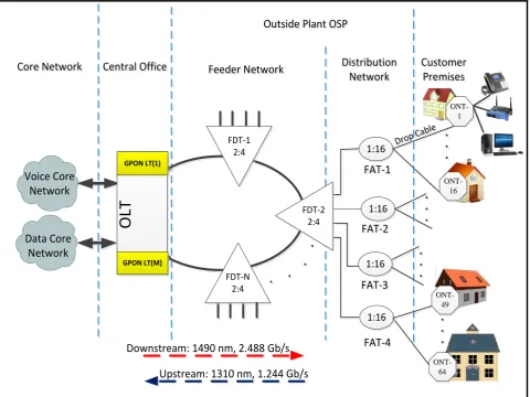
Fig. 1 GPON FTTH access network architecture
3.1 FTTH Core Network
The core network includes the internet service provider ISP equipments (typically BRAS and AAA server), PSTN (packet switched or the legacy circuit switched) and cable TV provider equipment.
3.2 Central Office
The main function of the central office is to host the OLT and ODF and provide the necessary powering. Sometimes it might even include some (or all) of the components of the core network.
3.3 FTTH Feeder Network
The feeder area extends from optical distribution frames (ODF) in the central office CO to the distribution points. These points, usually street cabinets, called Fiber Disruption Frames FDT where level-1 splitters usually reside. The feeder cable is usually connected as ring topology starting from a GPON port and terminated into another GPON port as shown in Fig.1 to provide type B protection. Level-1 splitters with a spilt ratio of 2:4 have been employed by our design. This type of splitters enables the feeder to be connected to 2 GPON ports from one side (for type B protection) and feeds a total of 4 distribution cables from the other side. The fiber cable running between the CO and level-1 splitter is called Level-1 fiber [2]
3.4
FTTH Distribution Network
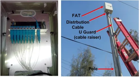
Distribution cable connects level-1 splitter (inside the FDT) with level-2 splitter. Level-2 splitter is usually hosted in a pole mounted box called Fiber Access Terminal FAT usually placed at the entrance of the neighborhood. In the design adopted by this paper level-2 splitter is 1:16, which means each FAT serves 16 homes. The fiber cable running between level-1 splitter and level-2 splitter is called level-2 fiber [2].
3.5 User Area
In the user area, drop cables, or level-3 fibers [2], are used to connect the level-2 splitter inside the FAT to the subscriber premises. Drop cables have less fiber count and length ranges up to 100 meters. Drop cables are designed with attributes such as flexibility, less weight, smaller diameter, ease of fiber access and termination. For ease of maintenance, usually an aerial drop cable is terminated at the entrance of the subscriber home with a Terminal Box TB, then an indoor drop cable connects the TB to an Access Terminal Box ATB reside inside the home. Finally a patch cord connects the ONT to the ATB.
- Scalability - Survivability - Functionality
- Construction and maintenance costs - Network upgradeability
- Operability and suitability over designed network lifetime.
4. TRAFFIC FLOW IN GPON FTTH
ACCESS NETWORKS
The data is transmitted from OLT to ONT in downstream as a broadcast manner and as a Time Division Multiplexing (TDM) in upstream [32].The wavelength of the downstream data is 1490 nm, voice and data services from core network transported over the optical network reaches the OLT and are distributed to the ONTs through the FTTH network by means of power splitting. Each Home receives the packets intended to it through its ONT. The upstream represents the data transmission from the ONT to OLT. The wavelength is 1310 nm. If the signals from the different ONTs arrive at the splitter input at the same time and at the same wavelength 1310nm, it
results in superposition of different ONT signals when it reaches OLT. Hence TDMA [1] is adopted to avoid the interference of signals from ONTs. In TDMA time slots will be provided to each user on demand for transmission of their packets. At the optical splitter packets arrive in order and they are combined and transmitted to OLT.
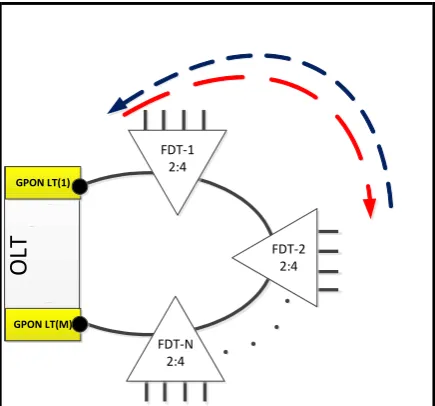
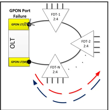
Type B protection [27], [34] is used in the design of the GPON FTTH access network presented in this paper. It provides redundancy against both feeder and GPON port failures. In this type of the protection, each fiber strand in the feeder cable is connected to two GPON ports in the OLT as shown in Figure 1. One of the ports is configured as active and the other as standby. Figure 2 shows the normal direction of traffic, once a failure in a fiber strand is happened, the OLT automatically activates the standby GPON port to broadcast a copy of the downstream traffic to feed the FDTs beyond the failure point from the other direction as shown in Figure 3. This standby GPON port will also receive the upstream traffic of the isolated feeder portion. Figure 4 depicts the situation when the active GPON port itself has a failure, in this case the OLT automatically divert the optical signal to the protection line through the standby GPON port.
GPON LT(1)
GPON LT(M)
O
LT
FDT-N 2:4
FDT-2 2:4 FDT-1
[image:4.595.58.276.327.530.2]2:4
Fig. 2 Normal direction of traffic flow
GPON LT(1)
GPON LT(M)
O
LT
FDT-N 2:4
FDT-2 2:4 FDT-1
2:4
[image:4.595.321.538.330.544.2]Link Failure
Fig. 3 Type B protection in GPON FTTH access network, the OLT send and receive traffic through the standby
GPON LT(1)
GPON LT(M)
O
LT
FDT-N 2:4
FDT-2 2:4 FDT-1
2:4 GPON Port
[image:5.595.57.278.69.292.2]Failure
Fig. 4 Type B protection in GPON FTTH access network, the OLT sends and receives traffic through the standby
GPON ports to overcome GPON-port failure
5. DESIGN OF THE GPON FTTH
ACCESS NETWORK
The Design of an FTTH access network is challenging one; it needs to compromise different factors including size, cost, and scalability. There is no standard FTTH access network model as the viability of access networks strongly depends on the subscriber density (subscribers per km2) and on settlement structures, thus the modeling has to rely upon a concrete settlement structure, a given country, and the results derived depend on that country [18].
To design the Outside Plant OSP, Desk top planning does not work, each root is surveyed physically and then planned accordingly using knowledge and experience. International standards cannot be applied as each country has its own unique underground factors. Ground thermal line or freeze line should be considered to identify the point in the underground where the temperature of the surrounding soil remains constant (not freezing nor overheating) thus allowing for a constant temperature for the FO cable to lay in. Another important factor that should be addressed is to decide the depth and the type of the backfill material necessary to reduce the ground vibration effects.
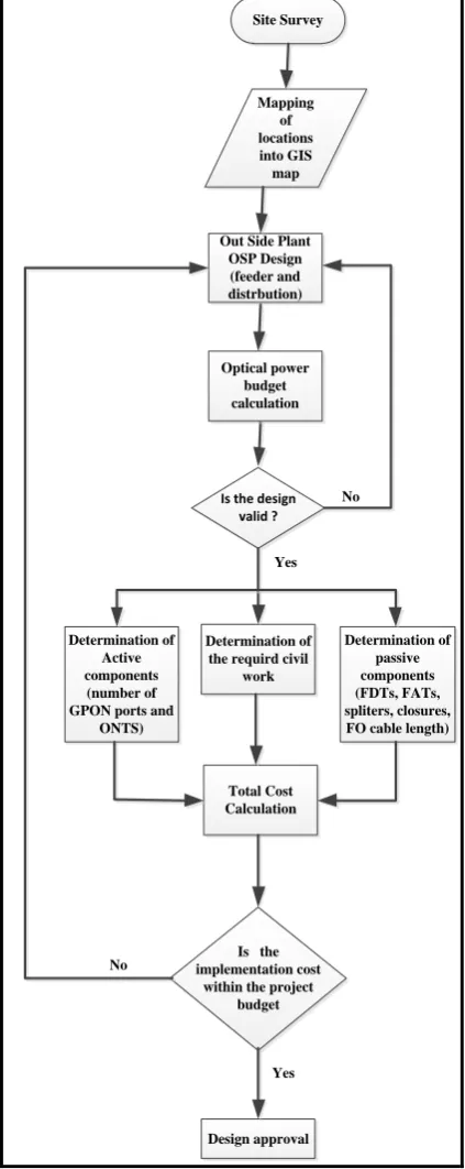
Figure (5) summarizes the sequence of steps involved in the design of the FTTH access network in discussion. In reference to Figure 1, the design starts with the customer premises, moving backward until reaching the central office in a bottom-up approach. The network particularly considered in this paper is required to provide service (voice and data) to a total of 1000 users in 238 locations. According to the geographical separation of these locations and the number of users per individual location, 185 FATs are used to connect
these locations to the network. Nearby locations are served by a common FAT while each of the diverse locations are served a by a dedicated FAT. Huawei MA5600T OLT located at the CO is used as the access platform. This OLT supports a 16 slots of 8-port GPON cards. Two level of splitting is used to provide a total splitting ratio of 64. Level-1 splitters are 2-4 while level-2 splitters are 1:16. This means that each GPON port can serve a total of 64 users. A bottom-top approach is used to determine the required number of GPON ports. By simple math, we can see that 16 GPON ports with 64 split ratio are quite enough to serve 1000 users. This statement is true for FTTH networks where the locations are geographically located close to each other and the number of users distributed evenly among locations, which is not our case. Due to the constraints of our network, the number of required ports will be calculated depending on the number of FATs. According to the 64 splitting ratio, each GPON port can serve a total of 4 FATs as each FAT contain 1:16 splitter, then 48 GPON ports are required to serve the 185 FATs. Another bunch of redundant 48 GPON ports is used to provide type-B protection. The total number of OLT GPON cards used by the design will be 12, with 6 cards in each direction. 6 FDTs are used to hold level-1 splitters with each FDT hold 8 splitters. As a result each FDT will be connected to one OLT card using 8 Fibers from one direction and to the backup card using 8 fibers from the other direction as shown in Figure 6. Two feeder rings are used, the first feeder consists 12 fibers among which 8 are connected to the 8 level-1 splitters inside FDT-3. The second feeder forms the second ring connecting the other 5 FDTs. The extra 4 and 32 fibers, in the first and second feeders respectively, are reserved for future expansion or maintenance.
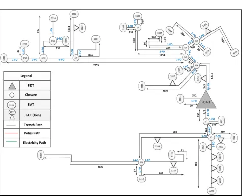
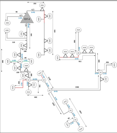
Figures 7 and 8 show the distribution network connected to FDT-3 and FDT-4 respectively, due to space limitation the other distribution networks will not be presented, however the design procedure discussed above is followed in the design of all distribution networks of the project . The legend presented in Figure 7 applies equally in Figure 8. Three distribution fiber cables connected to FDT-3, namely 3/1, 3/2, and 3/3. The circles in the figures refer to splicing closures. The number inside the circle refers to the FDT/closure numbers, for example, 4/1 refers to the first closure in FDT-4. The FATs are presented as ellipses in the design, the number inside each ellipse indicates the FAT address. The terminology adopted with FATs is to use 4 digit numbering. The first digit from the left refers to the FDT code, the second digit refers to the distribution cable sequence number and the last two digits refer to the sequence number of the fiber strand used to connect that FAT. This terminology applies equally to distribution networks connected all other FDTs. For example, in Figure 5, FAT number 4121 is an FAT in the first distribution cable of FDT-4, and connected to the 21th fiber strand of that distribution cable. This terminology makes the design, implementation management, reporting and future expansion easier. Two symbols are used for the FATs, the semicircle refers to FAT which only hold level-2 splitter, while the semicircle over a triangle refers to an FAT which holds level-2 splitter and provide splicing-closure function as well. The lines refer to FO cables paths. The length of each
Site Survey
Mapping of locations into GIS map
Out Side Plant OSP Design (feeder and distrbution)
Determination of passive components (FDTs, FATs, spliters, closures, FO cable length) Determination of
Active components (number of GPON ports and
ONTS)
Determination of the requird civil
work
Is the implementation cost
within the project budget Is the design
valid ? Optical power
budget calculation
No
Yes
Total Cost Calculation
No
Design approval Yes
Fig. 5 GPON FTTH access network design steps
FDT-6
FDT-6
FDT-3
FDT-3
FDT-4
FDT-4
FDT-1
FDT-1
FDT-2
FDT-2
FDT-5
FDT-5 OLT
12-FO
[image:6.595.315.538.69.290.2]72-FO
Fig. 6 The feeder part of the GPON FTTH access network meters, is shown in the figures. The black lines represent trench paths, the red lines indicate areal paths, and the green lines refer to situations where electrical poles are used to carry distribution cables.
6. DESIGN VALIDATION
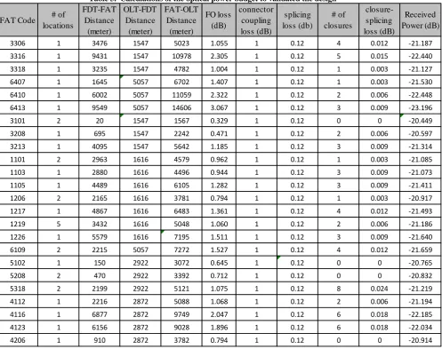
In order to assess the feasibility of the proposed design of the FTTH network and that each user in the network can receive adequate power , the total optical power loss between the GPON port of the OLT and that of the ONT should be considered. This loss can be summarized by the following equation:
𝑙𝑜𝑠𝑠 = 𝑙𝑐𝑎𝑏𝑙𝑒 + 𝑙𝑠𝑝𝑙𝑖𝑡𝑡𝑒𝑟 + 𝑙𝑠𝑝𝑙𝑖𝑐𝑒 + 𝑙𝑐𝑜𝑛𝑛𝑒 𝑐𝑡𝑜𝑟 (1)
Table (2) presents the definition and value of each parameter in equation 1.
[image:6.595.54.266.76.608.2]Table 2. Parameters contributing to the optical power loss in GPON FTTH access networks
Parameter Description Value
𝑙𝑐𝑎𝑏𝑙𝑒 Account for the loss in optical signal power as it traverse the fiber cable, it is
measured in dB/km. OTDR is used to measure the exact value of this parameter.
0.21 dB/km
𝑙𝑠𝑝𝑙𝑖𝑡𝑡𝑒𝑟 Refers to splitter insertion loss, it varies according to the splitting ratio. The
values of used for this parameter are obtained from datasheets of the corresponding splitter.
8 dB for level-1 splitter. 14 dB for level-2 splitter
𝑙𝑠𝑝𝑙𝑖𝑐𝑒 Represent the loss introduced due to splicing; it is measured by the fusion splice
machine. The value shown represent the maximum loss obtained
0.003 dB
𝑙𝑐𝑜𝑛𝑛𝑒𝑐𝑡𝑜𝑟 Manifests the loss introduced by connectors coupling. 0.2 dB
FDT-3 3 2 0 3 3202 3 1 0 1 3/1 1-FO 3/1 3 /2 1 3 -F O 3 2 0 1 3/2 3 2 0 4 3 2 0 5 3 2 0 6 3 0 2 7 3208 3209 3/3 3210 3 2 1 1 3212 3 2 1 3 3 3 0 1 3 /3 1 8 -F O 3317 3 3 1 8 3/4 3 3 0 2 3/5 3/6 3/7
3303 3306
3304 33
[image:7.595.60.539.193.580.2]05 3307 3/8 3309 3 3 0 8 3/9 3310 3 3 1 1 3312 3/10 3/11 3314 3 3 1 3 3/12 3315 3 3 1 6 1 2 -F O 5-FO 2-FO 5 -F O 2-FO 1 -F O 1-FO 1-FO 2-FO 1-FO 14 -FO 7 -F O 2-FO 1-FO 4-F O 1-FO 1-FO 2-FO 1-FO 1 -F O 7-FO 4-FO 2 -F O 1 -F O 2 -F O 1 -F O 1-FO 2-FO 1 -F O 1-FO 1154 8 6 180 1 5 0 233 8 3 0 2 9 7 324 20 760 11 40 361 7855 866 135 1 0 3 3 5 4 0 4 0 271 2020 1 2 1 5 20 400 1 5 0 123 1 6 5 960 3 8 0 2820 71 240 9 7 360 FDT Closure 4116 FAT 4117 FAT (Join) Trench Path Legend Poles Path Electricity Path
Fig. 7 The distribution network connected to FDT-3
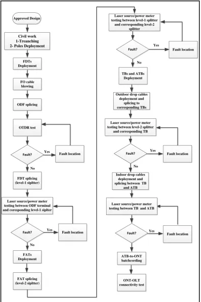
7. IMPLEMENTATION
An engineering project should be implemented according to a pre-defined sequence of steps. This is especially crucial to projects which involve a mixer of engineering activities, where an error in a certain stage might lead to a propagation of error in the subsequent stages. FTTH projects are amongst such projects where they involve a mixer of civil and technical works. Project implementation planning saves time, efforts and cost. Therefore, a careful consideration is given to this issue. Figure 8 shows the major steps implemented in this
FDT-4
4 /1 4301 2 4 -F O 4/3 1-FO 4 1 0 1 4102 4 1 0 3 4 1 0 4 4 1 06 410
[image:8.595.55.552.70.638.2]5 4 1 0 7 4108 4 1 0 9 4/2 4 1 1 1 4112 4 1 1 0 4/3 4113 4/5 4114 4/6 41 15 4116 4/4 4 1 1 7 4/7 4 1 1 8 4/1 4120 4119 4/8 4122 4121 4 1 2 3 4124 4201 4 2 0 2 4 2 0 4 4 2 0 3 4 2 0 5 4 2 0 6 4/2 6-FO 1 8 -F O 1-FO 1-FO 1 -F O 12-FO 2 -F O 1-FO 11-F O 3-FO 1-FO 2-FO 1-FO 1-FO 3-FO 6-FO 1 -F O 1-FO 8-FO 2 0 -F O 18 57 16 25 602 50 3 5 5 4 9 0 57 84 11 38 1366 6 8 4 426 811 5 6 8 6 5 5 255 90 110 100 5 4 5 3 0 0 5 6 1 220
Table 3. Calculations of the optical power budget to validated the design
FAT Code # of
locations
FDT-FAT Distance
(meter)
OLT-FDT Distance
(meter)
FAT-OLT Distance
(meter)
FO loss (dB)
connector coupling loss (dB)
splicing loss (db)
# of closures
closure-splicing loss (dB)
Received Power (dB)
3306 1 3476 1547 5023 1.055 1 0.12 4 0.012 -21.187
3316 1 9431 1547 10978 2.305 1 0.12 5 0.015 -22.440
3318 1 3235 1547 4782 1.004 1 0.12 1 0.003 -21.127
6407 1 1645 5057 6702 1.407 1 0.12 1 0.003 -21.530
6410 1 6002 5057 11059 2.322 1 0.12 2 0.006 -22.448
6413 1 9549 5057 14606 3.067 1 0.12 3 0.009 -23.196
3101 2 20 1547 1567 0.329 1 0.12 0 0 -20.449
3208 1 695 1547 2242 0.471 1 0.12 2 0.006 -20.597
3213 1 4095 1547 5642 1.185 1 0.12 3 0.009 -21.314
1101 2 2963 1616 4579 0.962 1 0.12 1 0.003 -21.085
1103 1 2880 1616 4496 0.944 1 0.12 3 0.009 -21.073
1105 1 4489 1616 6105 1.282 1 0.12 3 0.009 -21.411
1206 2 2165 1616 3781 0.794 1 0.12 1 0.003 -20.917
1217 1 4867 1616 6483 1.361 1 0.12 4 0.012 -21.493
1219 5 3432 1616 5048 1.060 1 0.12 2 0.006 -21.186
1226 1 5579 1616 7195 1.511 1 0.12 3 0.009 -21.640
6109 2 2215 5057 7272 1.527 1 0.12 4 0.012 -21.659
5102 1 150 2922 3072 0.645 1 0.12 0 0 -20.765
5208 2 470 2922 3392 0.712 1 0.12 0 0 -20.832
5318 2 2199 2922 5121 1.075 1 0.12 8 0.024 -21.219
4112 1 2216 2872 5088 1.068 1 0.12 2 0.006 -21.194
4116 1 6877 2872 9749 2.047 1 0.12 6 0.018 -22.185
4123 1 6156 2872 9028 1.896 1 0.12 6 0.018 -22.034
4206 1 910 2872 3782 0.794 1 0.12 0 0 -20.914
8. CONCLUSIONS
This paper presented a detailed design and implementation of a type B protected GPON based FTTH access network serving 1000 users, it adopted engineering approach to emphasize practical aspects and field experience. The design procedure followed a bottom top approach, in which the size of the network and its components is defined after analyzing the requirements, the number of locations, the geographical separation and the available infrastructure. OSP design should be based on the physical survey of each root, desk top design causes wasting of a lot of time and cost when some roots needs to be redesigned to fit with the physical environments or to avoid certain obstacle.
No Yes
Fault location
No
Yes
Fault? Fault location
Yes
Fault location
Yes
Fault location No
Yes
Fault location Fault?
No TBs and ATBs
Deployment
Laser source/power meter testing between level-2 splitter
and corresponding TB Outdoor drop cables deployment and
splicing to corresponding TBs Laser source/power meter testing between level-1 splitter
and corresponding level-2 splitter
Fault?
Fault?
FAT splicing (level-2 sipltter)
FATs Deployment
Laser source/power meter testing between TB and ATB
Indoor drop cables deployment and splicing between TB
and ATB FDTs
Deployment
Civil work 1-Treanching 2- Poles Deployment
Approved Design
OTDR test FO cable blowing
ODF splicing
Fault?
FDT splicing (level-1 sipltter)
Laser source/power meter testing between ODF terminal and coresponding level-1 siplter
ONT-OLT connectivity test
[image:10.595.101.496.71.662.2]ATB-to-ONT batchcording
PVC pipe
[image:11.595.58.540.69.430.2]HDPE duct
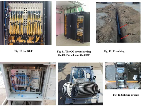
Fig. 10 the OLT Fig. 11 The CO room showing
the OLTs rack and the ODF
Fig. 12 Trenching
Fig. 13 Level-1 splitter inside the FDT Fig. 14 FDT splicing brackets
Fig. 15 Splicing process
[image:11.595.55.526.457.666.2]Fig. 16 OTDR testing screenshot
REFERENCES
[1] Stephan Smith, “Business class services over a GPON network,” in proc. IEEE Optical Fiber Communication Conference, 2006 and the 2006 National Fiber Optic Engineers Conference. OFC 2006.
[2] M. Chardy et al., “Optimizing splitter and fiber location in multilevel optical FTTH network,” European Journal of Operational Research: Elsevier B.V, pp. 430-440, May 2012
[3] Deeksha Kocher et al., “Simulation of fiber to the home triple play services at 2 Gbit/s using GE-PON architecture for 56 ONUs,” Optik: Elsevier B.V, pp. 5007-5010, 2013
[4] Deepak Malik et al., “ Quality of service in two-stages epon for fiber-to- the-home,” International Journal of Soft Computing and Engineering (IJSCE), vol. 2, No. 2, pp.387-390, May 2012.
[5] Mohd Syuhaimi Ab-Rahman et. al, “New optical splitter design for application in fibre-to-the home passive optical network using virtual lab platform,” Journal of Computer Science: Science Publications, pp. 846-871, 2012.
[6] James O. “High speed data to the home - an update,” in proc. 2011 IEEE International Conference on Consumer Electronics (ICCE), pp. 663-664, 2011.
[7] M. S. Rahman et al., “Ideal and non ideal condition analysis based on protection scheme in distributed fiber for immediate split Ftth-pon,” Journal of Applied Science: Asian Network for Scientific Information, pp. 1026-1032, 2011
[8] Duo Peng and Peng Zhang, “Design of Optical Integrated Access Network Based on EPON,” in proc. 2011 International Conference on Electronics and Optoelectronics (ICEOE 2011), pp. 65-68, 2011
[9] Rajneesh Kalera and R.S. Kalerb, “Simulation of Fiber to the Home at 10 Gbit/s using GE-PON architecture,” Optik: Elsevier B.V, pp. 1362-1366, 2011.
[10]Bogyum KIM , Wonhyung LEE and Jinwoo HAN, “Outside Plant Architecture of Fiber-based Access Network,” Digest of the 9th international conference on optical Internet (COIN 2010).
[11]Edoardo Bonetto, Marco Mellia, and Michela Meo, “Energy Profiling of ISP Points of Presence,” in proc. IEEE ICC'12 Workshop on Green Communications and Networking, pp. 5973-5977, 2012.
[12]Salah Al-Chalabi, “Optically Powered Telephone System over Optical Fiber with High Service Availability and Low Risk of Investment in FTTH Infrastructure,” IEEE Communications Magazine, August 2012.
[13]Christoph Lange and Andreas Gladisch, “On the Energy Consumption of FTTH Access Networks,” IEEE,
[14]Andreas Gladisch , Christoph Lange and Ralph Leppla, “Power efficiency of optical versus electronic access networks,” in proc. ECOC 2008, 21-25 September 2008, Brussels, Belgium, pp. 1-4.
[15]Juan Rendon Schneir and Yupeng Xiong, “Economic implications of a co-investment scheme for FTTH/PON architectures,” Telecommunications Policy: Elsevier B.V, pp. 849-860. 2013.
[16]Stephan Jay, Karl-Heinz Neumann n and Thomas Plückebaum, “Comparing FTTH access networks based on P2P and PMP fibre topologies,” Telecommunications
Policy: Elsevier B.V, 2013,
http://dx.doi.org/10.1016/j.telpol.2013.04.010i.
[17]Zijad Havic and Branko Mikac, “Software tool for assessment of FTTH access networks,” in proc. 12th International Conference on Telecommunications - ConTEL 2013, pp. 47-52, June 2013.
[image:12.595.53.506.71.321.2][18]Steffen Hoernig et al., “The impact of different fiber access network technologies on cost, competition and welfare,” Telecommunications Policy: Elsevier B.V, 2012, pp. 96-112.
[19]Marco Araújo and A. Manuel de Oliveira Duarte, “A comparative study on cost-benefit analysis of fiber-to-the-home telecommunications systems in Europe,” in proc. IEEE 2011 Baltic Congress on Future Internet and Communications, pp. 65-69.
[20]Marco Forzati et al., “The uncaptured value of FTTH networks,” ,” in proc. IEEE 2011 13th International Conference on Transparent Optical Networks ICTON-2011, pp. 1-4.
[21]Dirk Breuer et al., “Opportunities for Next-Generation Optical Access,” IEEE Communications Magazine, February 2011.
[22]Sotiria Chatzi and Ioannis Tomkos, “ Techno-economic study of high–splitting ratio PONs and comparison with conventional FTTH-PONs/FTTH-P2P/ FTTB and FTTC deployments,” in proc. IEEE 2011 Optical Fiber Communication Conference and Exposition and the National Fiber Optic Engineers Conference, pp.1-3. [23]Sofie Verbrugge et al., “Research Approach towards the
Profitability of Future FTTH Business Models,” in proc. 2011 Future Network & Mobile Summit, pp. 1-10, 2011. [24]Zijad Havic, “Economic Model Computing for FTTH
Access Network,” in proc. IEEE 5th International Conference on Pervasive Computing and Applications, pp. 218-222, 2010.
[25]Bruno Van Den Bossche et al., “ Maximizing the return on investment for FTTX-rollout through the use of GIS street maps and geomarketing data,” in proc. IEEE 2010 9th Conference of Telecommunication, Media and Internet, pp.1-6, 2010.
[26]Rong Zhao et al., “Dynamic Migration Planning towards FTTH,” in proc. IEEE 2010 9th Conference of Telecommunication, Media and Internet, pp.1-6, 2010. [27]Boyer Heard, “Availability and cost estimation of
secured FTTH architectures,” in proc. IEEE 2008 International Conference on Optical Network Design and Modeling, pp.1-6.
[28]Yinghui Qiu, “Availability estimation of FTTH architectures based on GPON,” in proc. IEEE 2011 7th International Conference on Wireless Communications, Networking and Mobile Computing, pp. 1-4.
[29]Jani Saheb Shaik, “FTTH deployment options for telecom operators,” www.sterlitetechnologies.com.
[30]Frank Effenberger et al., “An Introduction to PON Technologies,” IEEE Communications Magazine, March 2007, pp. 517-525.
[31]Cláudio Rodrigues et al., “Evolution of FTTH Networks Based on Radio-Over-Fibre,” in proc. IEEE 2011 13th International Conference on Transparent Optical Networks ICTON, pp. 1-4
[32]Satyanarayana Katlay and Abhinov Balagoni, “Technological and Cost based Analysis of Future-Proof Fiber Access Passive Networks: GPON and WDM PON,” arXiv, pp. 1-4, 2013.
[33]Jagjit Singh Malhotra, Manoj Kumar and Ajay K. Sharma, “Low cost solution to high capacity 32 × 32 channel FTTH duplex link employing triple play services,” Optik: Elsevier B.V, pp. 93-96, 2014.