Mitigation of Harmonics using D-STATCOM
Pujari Anusha
1S. Jayachandra
2T. Sudheer Kumar Reddy
31
PG Scholar
2,3Assistant Professor
1,2,3
Department of Electrical & Electronics Engineering
1,2,3
Sree Vidyanikethan Engineering College, Tirupati, Andhra Pradesh, India
Abstract— In a power system, the source currents are affected by the harmonics, which are introduced due to non-linearity or unbalance of loads. To mitigate these harmonics custom power devices can be used. D-STATCOM act as a shunt active power line conditioner for power quality improvements such as current harmonics, reactive power compensation and power factor improvement. In this project, the THD of the system is observed with a D-STATCOM with PI controller and without any compensators. The effect of replacing DC link by a Photo voltaic (PV) system is to be observed. In this project, conventional PI controller is replaced by a fuzzy logic controller and the THD of the system is observed with and without PV system. The performance of these controllers is compared, and suitable controller is proposed to increase power quality of system when renewable energy sources are introduced into the system. The whole work is to be performed in MATLAB/SIMULINK.
Keywords: Distribution Static Synchronous Compensator (D-STATCOM), Power Quality (PQ), Total Harmonic Distortion (THD), and Hysteresis Current Controller (HCC) Renewable Energy Sources (RES), Shunt Active Power Line Conditioner (SAPLC)
I. INTRODUCTION
The energy demand is increasing due to the increase in population. There will be decrease in the power generation. Renewable energy sources as a future energy solution for power generation. Renewable energy sources advantages are low maintenance cost, environmentally friendly, reduction of pollution. Photo voltaic is one of the major power sources, becoming more reliable and affordable than other power sources. Hence to maintain the continuous compensation of load using DC link voltage of the DC bus capacitor. Renewable energy sources in distribution systems causes issues in terms of voltage. Voltage Regulation, stability, and power quality problems like voltage sag, voltage swell, transients and harmonics, etc. To overcome these power quality problems using custom power devices. Custom power devices are DVR, UPQC, D-STATCOM. Here we are used PV based DSTATCOM this device more flexible and fast dynamic response to the disturbances. To reduce the total harmonic distortion of source currents using D-STATCOM. Few control strategies for grid connected inverter incorporating PQ problems have been proposed. Hysteresis current controller, P-Q control. The theory of P-Q controller to generate the reference current signals and hysteresis current controller are generating switching pulses for the gate drives of the grid interfacing inverter. The inverter act as a shut active filter to inject the compensated current to the system. To improve the quality of power supply using PI and Fuzzy controller. PI controller main aim is to maintain constant voltage at the point of load. In the load point R.M.S
voltage value is calculated that is there is no reactive power measurement calculation.
The PI controller generates the error signal to drive the error to zero. PI controller is a closed loop controller which is leaden sum of error and integrate that value. Conventional controller has the gain of steady state error to be zero for step input. The transient response of the PI controller in DC-link voltage will be very slow. To overcome this problem a better fuzzy logic controller is proposed to improve the transient response of the dc-link voltage. The DC link capacitor voltage is maintained using a fuzzy logic controller. Fuzzy controller is its robustness in system parameters and speed of operation is more. PI and Fuzzy both controllers are operated under steady state and transient state conditions. Now we are calculating the THD compared with and without using controllers.
A. Shunt Active Power Line Conditioner:
This device intended to improve the quality of power that is delivered to electrical load equipment. The term most often refers to a device that acts in one or more ways to deliver a voltage level and characteristics to enable load equipment, power conditioner refers to a voltage regulator to improve power quality. Shunt Active Power Line Conditioner is connected shunt in distribution system to regulate the reactive power, mitigate the current harmonics and improve the power factor.
B. Control Techniques:
[image:1.595.307.549.518.681.2]p-q control technique is used to generate the reference currents and Hysteresis current controller is used to generate the switching pulses for the gate drives of the grid interfacing inverter.
Fig. 1: SAPF with PV system [3]. Where:
vs = Source voltage Is = Source current IL = Load current P = Power h = harmonics
Coupling transformer: It is connected between source and Dstatcom to provide isolation harmonic filter to minimize unwanted harmonics produced by VSC and keep this harmonic within the specific limit.
Fig. 2: Typical V-I Characteristics of D-STATCOM [12] Where:
Vref- Reference voltage
ICmax- maximum capacitive current
ILmax- maximum inductive current at max voltage
II. MATHEMATICAL MODELLING OF CONTROLLERS The reference current extraction method is classified into time domain and frequency domain. The time-domain method is used to extract the reference current from the harmonic line current with simple algebraic computation. The frequency domain based on Fast Fourier Transformation (FFT) method provides accurate individual and multiple harmonic load current detection. Time domain is fast response compared to frequency domain.
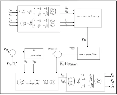
A. Instantaneous Real Power Theory
This theory derived from the conventional p-q theory or instantaneous reactive power theory. It operates in steady state or transient state as well as in generic voltage and current power systems which control the active power line conditioners in real time.
Fig. 3: Block diagram of the Instantaneous real power theory.
The p-q theory performs a Clarke transformation of stationary system of coordinates a − b − c to an orthogonal reference system of coordinates α − β. The a − b − c coordinate axis are fixed on the same plane, phase shifted by 120°. The instantaneous space vector voltage vsa and current isa set on a-axis, vsb and isb on b-axis, and vsc and isc on
[image:2.595.48.281.113.283.2]c-axis. The instantaneous space vector voltage(s) is transformed into the α − β coordinate voltage(s) by Clarke transformation as follows
Fig. 4: Phasor diagram representation of Clarke transformation.
[ vvα β] = √
2 3 [
1 −1
2 −
1 2
0 √3
2 −√
3 2
] [ vsa vsb vsc
] (1)
Similarly, the instantaneous space vector current(s) is transformed into the α − β coordinates current(s) by Clarke transformation that is given as
[iiα β] = √
2
3 [ 1 −1
2 −
1
2
0 √3
2 −√
3
2 ] [
isa isb isc
] (2)
The original orthogonal coordinates of voltage vα and current iα on α-axis and vβ and iβ on β-axis respectively. Let the instantaneous real-power be calculated from the α-axis and β-α-axis of the current and voltage. These are given by the conventional definition of real power as follows.
pac= vαiα+ vβiβ (3) The instantaneous real power pac passes through butter worth design based 50 Hz low pass filter for eliminating the higher order harmonic components, and it allows passing through fundamental components only. The output of the LPF component is considered as real power losses and it is denoted as p̅̅̅̅. The dc-power loss is calculated ac from the dc-capacitance voltage of the voltage sources inverter using the PI controller. The PI-controller determines the dynamic response and settling time in the dc-link capacitor voltage and dc-power losses. The dc-power losses are written as
pdc(loss) = [vdc,ref− vdc] [kP+ kI
s] (4) The instantaneous real-power p is calculated from the real power loss p̅̅̅̅ and the dc power loss pac dc(loss), it is calculated as
[image:2.595.52.283.484.672.2]conventional methods, the α − β coordinates currents are calculated as
[iicα cβ]=
1 vα2+vβ2{[
vα vβ vβ −vα] [
p
0]} (6) From the above equation, the orthogonal coordinate active power currents
The α − axis of the instantaneous active current is written as icαp =
vαp
vα2+vβ2 (7) The β −axis of the instantaneous active current is written as
icβp = vβp
vα2+vβ2
(8) Let the instantaneous power in the α − axis and β −axis is represented as pα and pβ respectively. They are given by the definition of real power as follows
p(t) = vαp(t)iαp(t) + vβp(t)iβp(t) (9) From the above equation, substituting the orthogonal coordinates α-axis active power and β-axis active power, calculate the real power as follows
p(t) = vαp(t) [ vαp vα2+v
β2] + vβp(t) [ vβp vα2+v
β2] (10) The ac component of the instantaneous power p(t)is related to the harmonic currents the instantaneous real-power extract the reference current required to component the current harmonics and reactive-power. The reference of the compensating currents isa∗ , isb∗ and isc∗ are calculated instantaneously without any time delay by using the instantaneous α − β coordinate currents.
[ isa∗ isb∗ isc∗
]= √2 3
[
1 0
−1
2 √
3 2
−1
2 −√
3 2]
[iicα
cβ] (11)
The small amount of real power is taken care through the controller by modulating fundamental component of reference current. The objectives of this algorithm is to compensate all undesirable power components. When the power system voltages are balanced and sinusoidal, it results simultaneously in constant instantaneous power and balanced sinusoidal currents in the ac-power supply.
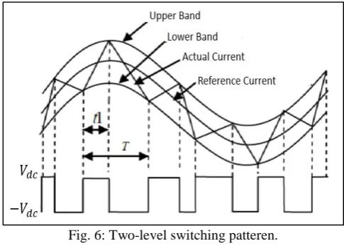
B. Hysteresis Current Controller
[image:3.595.306.549.67.240.2]The hysteresis current control method for active power line conditioner line currents can be carried out to generate the switching pattern of the inverter. Conventional hysteresis current control operates the voltage source inverter by comparing the current error e(t) against the fixed-hysteresis bands.
Fig. 5: Block diagram of hysteresis current controller.
Fig. 6: Two-level switching patteren.
This block diagram of two-level hysteresis current controller is above figure. The current error is the difference between the reference curent and the actual current. If the error current exceeds the upper limit of the hysteresis band, the upper switch of the inverter am is turned OFF nd the lower switch is turned ON. As a result, the current starts to delay.
The above switching pulses shows the ON and OFF switching pulses o drive the active power inverter. If the error current crossses the lower limit of the band, the lower switch is turned OFF and the upper switch is turned ON. As a result, the current gets back into the hysteresis band. Hence, the actual current is forced to track the reference current withih the hysteresis band
The phase-A switching performance is defined as
S={OFF if isa(t) > isa∗ (t) + hb ON if isa(t) < isa∗ (t) − hb
} (12)
The switching performance of phase-B and phase-C devices can be derived using hysteresis-band width hb. The two-level hysteresis controllers are widely used for active power line conditioner applications, because the circuit is very simple. However, it does not use zero voltage from the inverter dc-side; only positive and negative dc supply voltages are used to generate the required switching pulses. It is well known that the harmonics performance of two-level switching process. The three-level hysteresis current control approach provides superior performance on harmonic perspective.
III. RESULTS
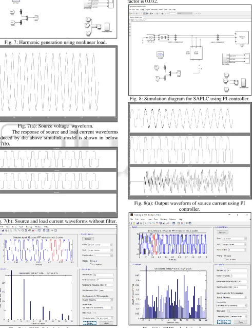
[image:3.595.49.287.619.751.2]Fig. 7: Harmonic generation using nonlinear load.
Fig. 7(a): Source voltage waveform.
The response of source and load current waveforms produced by the above simulink model is shown in below fig.7(b).
Fig. 7(b): Source and load current waveforms without filter.
Fig. 7(c): THD Calculation for source current
The above fig7(c) simulation diagram for harmonic generation without using shunt active power line conditioner and observe the source current and load current wave forms, calculate the total harmonic distortion is 26.01% and power factor is 0.032.
Fig. 8: Simulation diagram for SAPLC using PI controller.
Fig. 8(a): Output waveform of source current using PI controller.
[image:4.595.58.550.117.756.2]The above simulink models and output waveforms of source current to reduce the the source current harmonics in distribution system using D-STATCOM to improve the power factor and compensating the reactive power is calculated.
IV. CONCLUSION
The mathematical modelling analysed and also the current harmonics are reduced in distribution system usingD-STATCOM, and compensating the reactive power comparing the THD values using PI controller improve the power factor. Total harmonic distortion is reduced 26.11% to 2.82% using distributed static synchronous compensator.
REFERENCES
[1] Rubens Tadeu Hock, Yales Romulo de Novaes, and Alessandro Luiz Batschauer, “A Voltage Regulator for Power Quality Improvement in Low- Voltage Distribution Grids”, IEEE Transactions on Power Electronics, Vol. 33, No. 3, March2018.
[2] Kavita Kiran Prasad, Hareesh Myneni, Ganjikunta Siva Kuma, “Power Quality Improvement and PV Power Injection by DSTATCOM with Variable DC Link Voltage Control from RSC-MLC” IEEE Transactions on Sustainable Energy, P.P:1-1, 2018.
[3] Eklas Hossain, Mehmet rida tur, Sanjeevikumar Padmanaban, Selim ay and Imtiaj Khan, “Analysis and Mitigation of Power Quality Issues in Distributed Generation Systems Using Custom Power Devices”, IEEE Access., Vol.8, 12 March 2018.
[4] Faris Hamoud, Mamadou Lamine Doumbia, Ahmed Cheriti, Hakim Teiar, “Power Factor Improvement using Adaptive Fuzzy Logic Control Based D-STATCOM”, IEEE Twelfth International Conference on Ecological Vehicles and Renewable energies, 2017.
[5] Sabha Raj Arya, Bhim Singh, Ram Niwas, Ambrish Chandra and Kamal Al-Haddad, “Power Quality Enhancement Using DSTATCOM in Distributed Power Generation System”, IEEE Transactions on Industry Applications, 2016.
[6] Bijit Kumar Dey, Imran Khan, Nirabhra Mandal. “Mathematical modelling and characteristic analysis of Solar PV Cell” IEEE 7th Annual Information Technology, Electronics and Mobile Communication Conference (IEMCON), oct 2016.
[7] Papan Dey, Saad Mekhilef, “Current harmonics compensation with three phase four-wire shunt hybrid active power filter based on modified D–Q theory”, IET Power Electron., Vol. 8, Iss.11, pp. 2265–2280, 2015. [8] Mohammed Barghi Latran, “Mitigation of power quality
problems using distribution static synchronous compensator”, IET Journal, Vol. 8, issue 7,2015. [9] Maravathu Nagarjuna, P.C.Panda, Azmera Sandeep,
“Power Quality Factor “Improvement using Shunt Active Power Line Conditioner”, IEEE International Conference on Advanced Communication Control and Computing Technologies, 2014.
[10] Mr. Vinod S. Tejwani, Mr. Hitesh B. Kapadiya, Dr A S Pandya, G.P., Rajkot, Mr. Jignesh B Bhati, “Power quality improvement in power distribution system using
![Fig. 1: SAPF with PV system [3].](https://thumb-us.123doks.com/thumbv2/123dok_us/456814.1045346/1.595.307.549.518.681/fig-sapf-with-pv-system.webp)