International Journal of Emerging Technology and Advanced Engineering
Website: www.ijetae.com (ISSN 2250-2459, ISO 9001:2008 Certified Journal, Volume 7, Issue 6, June 2017)
405
An Application of Random Search Method to Optimal
Designing of Pipeline Systems
George Filatov
Professor, Doctor of Techn. Sciences, Ukrainian State University of Chemical Technology, Ukraine
Abstract - This paper considers the application of the method of random search for the optimal designing of shell-bar systems. Adduced the solution of the real problem of optimum design of the pipeline system. The main goal of the task - to minimize the cost of pipeline system, which includes: the pipeline, supports and foundations, at the performance of restrictions of the geometric nature and the restrictions on strength. Separately considered optimal designing of the support of pipeline system.
Keywords-- Optimization of Pipeline Systems, the Cost of System, Random Search Method.
I. INTRODUCTION
At the present stage of social development the introduction in the different branches of production methods of optimal design of structures, machines and equipment is the actual. With the advent of the computer the convenient for application have become the numerical methods of mathematical programming. One of these methods is the method of random search, which has a number of advantages compared with analytical methods. Among the applications of random search method for solving problems of optimal design of rod systems, caused by the need to produce, is the problem associated with the optimization of load-bearing structures of pipeline systems. When designing the spatial piping systems of different applications essential question becomes optimal placement of supports and the selection of the thickness of the wall of pipeline. It is known that as the global economic criterion of optimum designs to be considered their cost. Therefore, one of the most important requirements proposed for the piping systems is the need of a rational arrangement of system elements that lead to the minimum of cost of facilities in general.
II. OPTIMAL DESIGNING OF SOME PARAMETERS OF THE SUPPORTING STRUCTURE OF THE PIPELINE SYSTEM Consider the pipeline system (Fig. 1), consisting of a pipe supports and foundations.
The main parameters that have a decisive influence on the cost of such facilities, is the wall-thickness of the shell of the pipeline and the distance between the supports (span). The diameter of the pipeline always is a predetermined value − the function of technological requirements (with the consideration of unification).
In the general problem of the layout and calculation of the pipeline system one of the major question is the question about of the limiting value of acceptable span of pipe: an increase of this value leads to decreases the number of supports and foundations, is reduced the materials costs.
On the other hand, the increase of the spans number makes it necessary to increase the thickness of the pipe wall of the sheath, which causes an increase in weight and cost of the structure. Therefore, the question about the optimal placement of the supports is the general question of designing of piping systems.
In this article the marked problem is formulated as a problem of nonlinear mathematical programming. Statement of the problem is as follows: for the considered system are known: diameter of the pipeline
D
, the characteristics of the material of construction - the modulus of elasticityE
and the calculated resistanceR
, the specific gravity
of the concrete of foundations, reinforcement percentage
, height of the supportH
and the characteristic of the cross-sections of their beltsA
r
(r
radius of inertia of cross-section,A
–International Journal of Emerging Technology and Advanced Engineering
Website: www.ijetae.com (ISSN 2250-2459, ISO 9001:2008 Certified Journal, Volume 7, Issue 6, June 2017)
406
International Journal of Emerging Technology and Advanced Engineering
Website: www.ijetae.com (ISSN 2250-2459, ISO 9001:2008 Certified Journal, Volume 7, Issue 6, June 2017)
407
The described problem is mathematically reduced to determining the minimum of the objective function
C
, which is the cost of whole construction:3 2
1
C
C
C
C
(1) whereC
1 the cost of the pipeline;C
2 the cost of supports;C
3 the cost of foundations.By limiting the minimum wall thickness of the pipe with a predetermined value
, we obtain the value ofC
1 in form:
K
DL
K
DL
C
1 1 2 , (2) whereK
1 andK
2 − coefficients that depend on the price-list and the geometric characteristics.To determine the value
C
2 we write the expression for the cross-section area of compressed rod of support:2 2
H R NA , (3)
N
value, which approximates the coefficient of longitudinal bend
and which is determined in [1], depending on the grade of steel supports.The volume of all belts of support we can write the as follows:
l
L
H
R
qHL
V
23
2
. (4)Given the increase in weight of support due to the lattice and other elements, we obtain from (1) the value of the support:
l
L
H
R
qLH
K
C
23 3
2
5
,
2
, (5)3
K
a coefficient depending on the price-list.The value
C
3 for a centrally compressed foundation is determined by the following expression:qL
K
C
3
4 (6) 4K
coefficient depending on the design characteristics of the soil, of the depth of laying the foundation, of the specific weight of the concrete, of reinforcement ratio and of price-list. Now the unknown quantityC
is determined as follows:
K ql H R
qH K D
K D K
C 2 4
3 3
2 1
5 ,
2
. (7)On parameters
andl
we impose the restrictions:max min
max
min
;
l
l
l
, (8)q R D A
l 1
,
q D
A
l 0b n
1 ,
R i D B
l 1
. (9) Condition (8) limit the geometric dimensions and theconditions (9 - requirements of criteria of limit states [2], in which
A
1 andB
1 b
0
critical stresses the loss of stability at the bending, which are determined according to [2] and [3] and depending on the variable parameter
;
n the normal stresses from the longitudinal force caused by temperature deformation.International Journal of Emerging Technology and Advanced Engineering
Website: www.ijetae.com (ISSN 2250-2459, ISO 9001:2008 Certified Journal, Volume 7, Issue 6, June 2017)
408
K
q
x
H
R
qH
K
x
D
K
D
K
C
41 2
3
3 2
2 1
5
,
2
(10)and satisfy the restrictions:
max 2 2 min 2 max 1 1 min
1
x
x
;
x
x
x
x
, (11)q
R
x
D
A
x
1
1 2
,
q
D
A
x
1
1
0b
n ,R
ix
D
B
x
1
1 2 . (12)The solution of the task (10)-(12) we perform by the algorithm of continuous learning with a guide cone [4].
Consider as the numerical illustration, the problem of determining the optimal parameters of the pipeline system under next data:
D
1
,
2
м;E
2
,
1
10
5МPа;210
R
МPа;
0
,
3
кN/м3;
20
кN/м3;
18
H
m;
1
,
5
;
0
,
4
10
4;50
International Journal of Emerging Technology and Advanced Engineering
Website: www.ijetae.com (ISSN 2250-2459, ISO 9001:2008 Certified Journal, Volume 7, Issue 6, June 2017)
409
Fig.2. The trajectory of the search of minimal cost of the pipeline system
The search was performed out of the start point with coordinates
x
1
1
,
0
m;x
2
0
,
012
m. The initial parameters of search were taken such: the step length in the normalized areaa
0
,
2
; angle opening of cone
1
rad; the number of tests on one stepm
5
. Then the step was decreased tilla
32
,
and m had the values
0
,
5
,10
m
.
In Fig.2 is depicted the trajectory of search: a -17) shows the trajectory of search at the first finding of minimum of objective function, the dotted line shows the trajectory of ascent
(17-quality fu -50) in
extremal point, with coordinates
0
,
00625
m andl
13
,
5
m. The value of objective function48
,
164
min
International Journal of Emerging Technology and Advanced Engineering
Website: www.ijetae.com (ISSN 2250-2459, ISO 9001:2008 Certified Journal, Volume 7, Issue 6, June 2017)
410
III. OPTIMAL DESIGNING OF PIPE SUPPORTS
At the designing of piping systems sufficiently important is the choice of the geometric parameters of supports, which are usually are manufactured in the form of rod construction. Each pipeline system includes a number of different final and intermediate supports. The supports provide stability of the entire structure and perceive the vertical load and the load in the horizontal plane. Of considerable interest causes the choice of support sections and the geometry of its elements that lead to minimum weight of support as a whole. It is known that increasing the support size decreases the efforts in the belts; at this increases the length of the grating elements and hence its weight.
The problem is formulated as follows: are known the of height support
H
, vertical and horizontal loads on support, respectively, the longitudinal effortN
and transverse force theQ
, the design resistance of the material of support . Required to find the optimal geometrical parameters: the distance among the beltsb
, the panel heighth
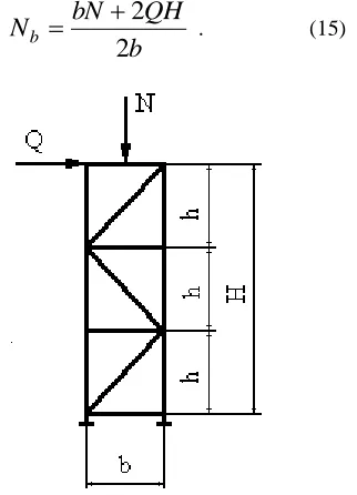
and dimensions of the elements.As an object for study, consider an intermediate support with two flat belts, the cross-sections of which we take in form of tube (Fig. 3), although for subsequent calculations the choice of the form of transverse sections of elements principle importance don’t have.
п
n
the number of beltsr br
b
A
A
A
,
,
cross-sectional areas of struts, braces (sloping rods) and racks;r br
b
d
d
d
,
,
wall thickness of belts, braces, racks;l
br the length of braces;
b
beltsh
the specific gravity of the supportr
radius of inertia of the cross section of the support element. For the squarer
max
4
cm and2
min
r
cm. The full weight of support:
h
H
d
l
h
H
bd
Hd
n
G
b
b
b r
r br br
br (13)Linear weight of one meter of support:
h
l
d
h
b
d
d
n
g
b
b
b r
r br
br br (14)If in the researched section acts longitudinal force
N
and transverse forceQ
, the expression for the effort in the belt takes the form:b
QH
bN
N
b2
2
[image:6.612.377.538.138.361.2]
. (15)Fig. 3. The calculated scheme of intermediate support of pipeline system
It is known that in compressed rack the stresses is equal to:
A
N
. (16)Using the data of [2], we write the expression for the coefficient of longitudinal bending:
2 4
2
10
24
,
3
1
r
H
b
. (17)For the elements of tubular form
r
0
,
35
d
. So we have2 4
2
10
24
,
3
1
b b
d
H
. (18)In the limiting condition
R
. Consequently:R
d
H
d
N
b b
b b
b
2 4
2
10
24
,
3
1
. ( 19)International Journal of Emerging Technology and Advanced Engineering
Website: www.ijetae.com (ISSN 2250-2459, ISO 9001:2008 Certified Journal, Volume 7, Issue 6, June 2017)
411
0
10
24
,
3
4 2 2
H
R
N
d
b bb
(20)and solving it, we determine the value of
d
b:4 2 2
10
24
,
3
4
2
H
B
B
d
b
, (21)where:
R
N
B
b b
.For the rack loaded with force, we obtain an expression for
r
d
: 4 2 2 2 2 210
24
,
3
4
2
b
R
Q
R
Q
d
r rr
(22)Accordingly, for sloping rod:
4 2 2 2 2 2
10
4
,.
3
4
2
br br br br br brl
R
N
R
N
d
, (23)where:
b
b
h
Q
N
br 2 2
.Due the fact that the expression (14) includes parameters of the cross-sections of elements selected by the calculated resistance, the strength condition is satisfied automatically. To solve the problem it is only necessary to impose restrictions on the limit flexibility of the compressed elements. Denoting the limit flexibility of belts, sloping rods and racks, respectively, as
b,
br,
r, and in view of the fact that for the tubular elementsd
r
0
,
35
, we obtain the following restrictions:b b
H
d
35
,
0
, br brH
d
35
,
0
, r rH
d
35
,
0
. (24)Introducing the notation
x
1
h
andx
2
b
and substituting in expression (14, 21 -24), we arrive at the nonlinear programming problem: find a non-negative valuesx
1 andx
2, that would deliver a minimum of the objective function (the linear weight of one meter of support):
3 2 2 2 1 2 2 3 2 1 2 2 2 3 2 2 2 2 2 410
24
,
3
4
10
24
,
3
4
10
24
,
3
2
2
10
78
Ф
x
x
R
N
x
R
Q
x
R
N
R
N
R
Q
R
N
B br b
b
r br(25)
at the performance of restrictions:
0
35
,
0
10
24
,
3
4
2
4 2 2 2 2 2
H
H
R
N
R
N
b b b b b
; (26)0
35
,
0
10
24
,
3
4
2
4 22 2 2 2 2 2
x
x
R
N
R
Q
r r r r
; (27)
0
,
35
0
10
24
,
3
4
2
2 2 2 1 4 2 2 2 1 2 2 2 2
x
x
x
x
R
N
R
N
br br br br br
International Journal of Emerging Technology and Advanced Engineering
Website: www.ijetae.com (ISSN 2250-2459, ISO 9001:2008 Certified Journal, Volume 7, Issue 6, June 2017)
412
The solution of set task is performed by a random search using an algorithm of guide cone [4].
Consider the optimal designing of the flat support (Fig. 3.13) with the following initial data:
N
2000
кN;25
Q
кN;R
210
МPа;H
1
,
5
m;
b
120
,150
р с
;
b
0
,
01
m;
с
р
0
,
006
m;6
1
h
m;1
b
6
m.Search was carried out of three starting points, two of which were selected randomly. The value of the initial step was taken
2
,
0
a
in the normalized area with the following decreasing tilla
32
. The following results were obtained: кN/m,h
4
,
25
m,b
3
,
1
m.REFERENCES
[1] Likhtarnikov Y.M. Metal constructions. − M .: Gosstroiizdat, 1968, 324p.
[2] Lubin AE Steel construction of pipeline systems // In coll. "Reviews on the design of metal structures ".− M .: TSINIS Gosstroy SSSR. 1971. Vol. 1/9 / P. 24- 30. [3] Zhu S.J., Prager B. Recent developments in the optimal
: IL.