International Journal of Emerging Technology and Advanced Engineering
Website: www.ijetae.com (ISSN 2250-2459,ISO 9001:2008 Certified Journal, Volume 4, Issue 12, December 2014)
Reduction of Current Harmonics Using SVPWM Control for
Shunt Active Filter
S. Dhanalakshmi
1, G. J. Pauline Jothi Kiruba
2, P. Mercy
31,2,3
Assistant Professor/EEE, INFO Institute of Engineering, India
Abstract --- As the use of power electronic equipment is spreading, the degradation of the power quality in the utility networks is increasing and is becoming a major problem. Limiting the current distortion is therefore a concern for both utilities and consumer. Power converters such as rectifiers, power supplies and at a higher power level, arc furnaces are the sources of harmonics. This harmonics can be reduced by using the shunt active filter. There are many control strategies to reduce harmonics. This paper presents space vector PWM control strategy for extracting reference currents of shunt active filters under non-linear load conditions by using Genetic Algorithm. The three-phase, three-wire, and seven level cascaded multilevel inverter is used as a medium-voltage shunt active power filter. The effectiveness of the proposed control algorithm is demonstrated by computer simulation and experimental results of a shunt active filter for a three-phase three wire distribution system with non-linear loads.
Keywords---Harmonic Compensation, Shunt Active Power Filter, Multileve inverter, Space Vector Pulse Width Modulation Control Strategy, Genetic Algorithm.
I. INTRODUCTION
Highly automatic electric equipments, in particular, cause enormous economic loss every year. Owing both power suppliers and power consumers are concerned about the power quality problems and compensation techniques. Power electronic converters act as sources of voltage or current harmonics, and if these are of a sufficient size, system voltage distortion and even grid stability problems can occur [2], [3]. Active power filters are grid connected power converters, which have been developed to mitigate the effects of nonlinear loads. The shunt active filter (SAF) is one such device. It is designed to inject current harmonics [10] into the distribution grid, which exactly cancel the polluting currents caused by disturbing nonlinear loads [1], [4]. In recent years, single-phase electronic equipments have been widely used in domestic, educational and commercial appliances.
In other words, those equipments draw non-sinusoidal currents which pollute the utility line due to the current harmonics generated by the nonlinear loads [1]. It is noted that non-sinusoidal current results in many problems for the utility power supply company, such as: low power factor, low energy efficiency, electromagnetic interference (EMI), distortion of line voltage etc. Several control strategy like PI, PID and Fuzzy controller [9] are developed for shunt active filters.
[image:1.595.308.541.610.679.2]The Problem with the PI and PID controller is that the response time will be very high and also the settling time is high, Total harmonic distortion is more, Power factor is low. Fuzzy controller has problems like redundancy, need of unique numbers for iteration. Though several control strategies[11] have been developed but still one control theory, space vector pulse width modulation methods are always dominant. The shunt active filter with voltage source inverter will have more Total Harmonic Distortion. This problem can be avoided by using Multi level inverters. In this paper seven level cascaded shunt active filter is proposed. In the proposed system, Total harmonic Distortion is very low and Power Quality is improved. To validate current observations, Extensive Simulations are carried out with Genetic Algorithm for space vector pulse width modulation methods for nonlinear load conditions and adequate results were presented. On observing the performance, space vector pulse width modulation control strategy with Genetic Algorithm for mitigation of current harmonics is quite good over other control technique.
Figure 1. Shows a basic architecture of three-phase - three wire shunt active filter
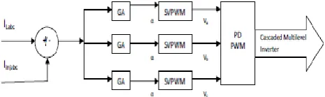
Figure 2. Shows A Control Block Diagram Of Shunt Active Filter.
II. SHUNT ACTIVE FILTER
The shunt active filter approach[3] is based on the principle of injection of harmonic currents in to the ac system, of the same amplitude but opposite in phase to that of the load harmonic currents.
Non Linear Load
7 Level Cascaded Multilevel inverter GA Based
PWM Control
3ø 3 wire
supply
International Journal of Emerging Technology and Advanced Engineering
Website: www.ijetae.com (ISSN 2250-2459,ISO 9001:2008 Certified Journal, Volume 4, Issue 12, December 2014)
647 As the number of these loads increased, harmonics currents generated by these loads may become very significant.
These harmonics can lead to a variety of different power system problems including the distorted voltage waveforms, equipment overheating, malfunction in system protection, excessive neutral currents, light flicker, in accurate power flow metering, etc. They also reduce efficiency by drawing reactive current component from the distribution network.
It is controlled to draw/supply a compensated current from/to the utility, such that it eliminates reactive and harmonic currents of the non-linear load. Thus, the resulting total current drawn from the ac mains is sinusoidal. Ideally, the APF needs to generate just enough reactive and harmonic current to compensate the non- linear loads in the line
.
III. CONTROL STRATEGY
3.1 Genetic Algorithm Control Scheme
Given the high number of parameters and the complexity of the controller arrangement, the design becomes quite critical and time consuming, even for an expert designer. An automatic optimization procedure based on GAs has therefore been studied, which is able to select a high-performance controller. With the GA design, it is possible to implement a digital linear controller, robust to parameter variation and different operating conditions and able to fulfill all the stringent performance requirements, while avoiding the use of more complex nonlinear structures.
A GA is a global search method that is inspired by the theories of evolution and natural selection. It operates on a population of potential solutions, termed individuals, applying the principle of evolution, simulated by means of mathematical operations that mimic the process of selection, crossover, and mutation.
The basis of the GA is that a “population” of solutions to a problem is composed of “chromosomes” which are strings encoding the solutions. These chromosomes are formed from the combination of optimization variables called “genes.”
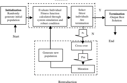
A GA-based routine starts with a population of individuals generated randomly and during each iteration, generates successive populations of strings through three operators: reproduction, crossover, and mutation. Individuals in the current population are evaluated using a measure of their objective function values, called “fitness functions.” A fitness function measures the fitness of an individual to survive in a population of individuals.
The GA will seek the solution that maximizes or minimizes the fitness function. The GA optimization process for controller parameters may be achieved “online” or “offline.” Online optimization embeds the operation of the GA with the normal working of the controller hardware. Each set of controller parameters is derived from a particular chromosome, and the hardware undergoes a series of transient operations. Data sampled from these transients can then be used to evaluate the fitness function of each chromosome. Offline optimization employs a simulation model to evaluate potential controller parameters and has therefore been employed in this paper. Although it is dependent on the accuracy of the model employed, it avoids risking ill- suited control parameters on the system hardware.
The simulation for the active filter hardware was performed in Matlab/Simulink using the Power System Block set.
[image:2.595.320.583.351.524.2]
Figure 3. Genetic Algorithm Flowchart
3.2 Space Vector Pulse width Modulation
The basic idea of voltage space vector modulation is to control the inverter output voltages so that their Parks representation will be approximately equals the reference current vector. In the case of two level inverter, the output of each phase will be either +Vdc/2 or – Vdc/2. The SVM technique can be easily extended to all multilevel inverters. Space-vector PWM methods generally have the following features: good utilization of dc-link voltage, low current ripple, and relatively easy hardware implementation by a digital signal processor (DSP). These features make it suitable for high-voltage high-power applications. As the number of levels increases, redundant switching states and the complexity of selecting switching states increases dramatically.
Initialization Randomly generate initial
population
Evaluate Individual Fitness function calculated through system simulation and
robust condition
Select fittest individuals
Are termination
criteria met?
Termination -Output Best Solution
Cross over
Generate new population
Mutation Pc
Pm Start
End N
Y
International Journal of Emerging Technology and Advanced Engineering
[image:3.595.79.242.141.318.2]Website: www.ijetae.com (ISSN 2250-2459,ISO 9001:2008 Certified Journal, Volume 4, Issue 12, December 2014)
Figure 4 Basic switching vectors and sectors.
Vab=VaN-VbN
Vbc=VbN-VcN Vca=VcN-VaN
Phase Voltage
Van = 2/3 VaN -1/3VbN -1/3VcN
Fundamental Frequency component
[image:3.595.314.551.531.703.2]Vd = Van –VbnCOS60 - VcnCOS60 = Van –1/2Vbn -1/2 Vcn Vq = 0+VbnCOS30 - VcnCOS30
Table 1.
Switching Table for space vector Modulation
Voltag e Vector
s
Switching Vectors Line to Neutral Voltage
Line to Line Voltage
a b c Van Vbn Vc n
Vab Vbc Vca
V0 0 0 0 0 0 0 0 0 0
V1 1 0 0 2/3 1/3
-1/3 1 0 -1
V2 1 1 0 1/3 1/3
-2/3 0 1 -1
V3 0 1 0 -1/3 2/3
-1/3 -1 1 0
V4 0 1 1 -2/3 1/3 1/3 -1 0 1
V5 0 0 1 -1/3 -1/3 2/3 0 -1 1
V6 1 0 1 1/3 -2/3 1/3 1 -1 0
V7 1 1 1 0 0 0 0 0 0
IV.CASCADED MULTILEVEL INVERTER
Multilevel inverters achieve high-voltage switching by means of a series of accumulating voltage steps, each of which lies within the rating of the individual power devices. Due to amplitude-modulation possibilities with multilevel inverters, lower total harmonic distortion is the result. There are three basic multi level inverter types:
1) cascaded multilevel; 2) neutral point diode clamped; 3) flying capacitor.
The cascaded multilevel inverter has advantages over the other two inverter types, such as the least number of components which significantly reduces the cost in the MV range, modularized circuit layout, and soft switching capability without the need for lossy resistor–capacitor-diode snubbers which increase cost and size, especially in the MV range. The concept of this inverter is based on connecting H-bridge inverters in series to get a sinusoidal voltage output. The output voltage is the sum of the voltage that is generated by each cell. The number of output voltage levels are 2n+1, where n is the number of cells. The switching angles can be chosen in such a way that the total harmonic distortion is minimized.
One of the advantages of this type of multilevel inverter is that it needs less number of components comparative to the Diode clamped or the flying capacitor, so the price and the weight of the inverter is less than that of the two types. The synthesized voltage waveform is, therefore, the sum of the inverter outputs i.e. v = v1+v2+....+vm. The number of output phase voltage levels in a cascade multilevel inverter is then 2s+1, where s is the number of isolated dc sources in a cascaded multilevel inverter
Figure 5. Seven Level Cascaded Inverter
[image:3.595.44.289.559.784.2]International Journal of Emerging Technology and Advanced Engineering
Website: www.ijetae.com (ISSN 2250-2459,ISO 9001:2008 Certified Journal, Volume 4, Issue 12, December 2014)
[image:4.595.52.283.134.271.2]649
Figure 6 Output waveform of Single phase cascaded m+1 level inverter
For a three-phase system, the output of three identical structure of single-phase cascaded inverter can be connected in either wye or delta configuration.
Figure 5. illustrates the schematic diagram of wye-connected seven-level inverter using three H-bridge cells and three SDCSs per phase, which will be used to verify the concept of the optimized harmonic stepped-waveform technique. From Figure5, VAN is voltage of phase A, which is the sum of Va1, Va2, and Va3. The same idea is applied to phase B and phase C.
To synthesize seven-level phase voltage, three firing angles are required. The same three switching angles can be used in all three phase with delaying 0, 120, and 240 electrical degree for phase A, B, and C, respectively. According to three-phase theory, line voltage can be expressed in term of two- phase voltages.
V. SYSTEM PERFORMANCE
Increase in such non-linearity causes different undesirable features like low system efficiency and poor power factor. It also causes disturbance to other consumers and interference in nearby communication networks. The effect of such non-linearity may become sizeable over the next few years. Hence it is very important to overcome these undesirable features. Active power filters are now seen as a viable alternative over the classical passive filters, to compensate harmonics and reactive power requirement of the non -linear loads. The objective of the active filtering is to solve these problems by combining with a much-reduced rating of the necessary passive components.
Various topologies of active power filters have been developed. The shunt active power filter based on current controlled voltage source type PWM converter has been proved to be effective even when the load is highly non-linear. Most of the active filters developed are based on sensing harmonics and reactive volt-ampere requirements of the non-linear load and require complex control.
The main function of the SAF [13] is to compensate current harmonics [10] by injecting equal -but-opposite harmonic compensating current.
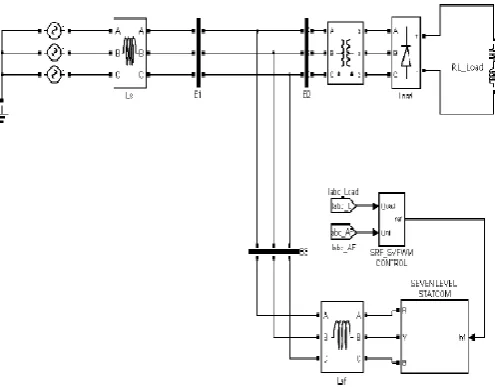
In this case the shunt active power filter operates as a current source injecting the harmonic components generated by the load but phase shifted by 180˚. A three phase three wire source is directly connected to the nonlinear load which induces the current harmonics in the load side.
To compensate the current harmonics SAF is connected in parallel to the nonlinear load. A Three Phase Transformer is used for injecting the harmonic components generated by the load. The nonlinear load used here is diode rectifier converts the ac to dc respectively. The three phase voltage source inverter [3] used in the existing system is replaced by seven level cascaded multilevel inverter.
The inverter is made up of number of MOSFET‟s and the pulses for the inverter are generated by PWM control circuit. The control circuit use space vector modulation techniques to generate PWM pulses. Also, the angle for the cascaded multi-level inverter is selected by Genetic Algorithm.
Genetic Algorithm gives accurate value of the angle compared to fuzzy logic controller used in the existing system. Thus the shunt active power filter is designed for the current harmonics and reactive power compensation of a nonlinear load [4].
A detailed simulation program of the schemes is developed to predict the performance for different conditions and Simulink models also has been developed for the same for different parameters and operating conditions. A Simulink model is developed to simulate the Genetic Algorithm based shunt active power filter in MATLAB/SIMULINK. The complete active power filter system is composed mainly of three-phase source, a nonlinear load, a voltage source PWM converter, and a SVPWM converter module. The seven level cascaded multilevel inverter module is modeled and simulated.
[image:4.595.320.568.559.752.2]International Journal of Emerging Technology and Advanced Engineering
[image:5.595.50.292.133.322.2]Website: www.ijetae.com (ISSN 2250-2459,ISO 9001:2008 Certified Journal, Volume 4, Issue 12, December 2014)
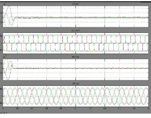
Figure 8. 3 phase 3 wire shunt active filter response with SVPWM Control Strategy
VI. CONCLUSION
This paper presents a three phase three wire shunt active power filter as a reliable and cost-effective solution to power quality problems. When the active filter is installed at a distorted and unbalanced distribution network, the harmonic are compensated by the active filter. Therefore, the source needs to supply only balanced, sinusoidal currents which are
in-phase with balanced posi-tive-sequence
fundamental voltage.
Table 2.
System parameters for multilevel inverter
The proposed low-cost solution allows the use of a large number of low-power active filters in the same facility, close to each problematic load (or group of loads), avoiding the circulation of current harmonics, reactive currents and neutral currents through the facility power lines. This solution reduces the power lines losses and voltage drops, and avoids voltage distortions at the loads terminals.
The proposed Shunt Active Filter (SAF) can compensate for variable nonlinear load currents. Proposed SAF adapt itself to compensate for variation in nonlinear currents.
REFERENCES
[1] Charles S. and Bhuvaneswari G. (2010) „Comparison of three phase shunt active power filter algorithms ‟ International Journal of Computer and Electrical Engineering, vol. 2, no. 1, pp. 175- 180
[2] Chen L. and Jouanne A. V. „A comparison and assessment of hybrid filter topologies and control algorithms‟ IEEE/PESC Ann. Meeting Conf, vol. 2, pp. 565-570
[3] Dixon J. W. Venegas G. and Moran L. A. (1997) „A series active power filter based on a sinusoidal current-controlled voltage-source inverter‟ IEEE Transactions on Industrial Electronics, vol. 44, no. 5, pp. 612-620
[4] Fujita H. and Akagi H. (1991) „A practical approach to harmonics compensation in power systems series connection of passive and active filters‟ IEEE Transactions on Industry Applications, vol. 27, no. 6, pp. 1020-1025
[5] Fujita H. and Akagi H. (1991) „Design strategy for the combined system of shunt passive and series active filters‟ in Industry Applications Society Annual Meeting , pp. 898-
[6] Jefferson A. (1999) „Adaptive VAR Compensation - a real solution to reactive power problems‟ issue. 33, pp. 16-19 [7] Kumar K. V. Surendar G. and Selvan M. P.(2008) „Performance
comparison of shunt active filter and hybrid active filter‟ NSC, pp. 71-76
[8] Kannan Karthik and Quaicoe J.E (2000) „Voltage compensation and harmonic suppression using series active and shunt passive filters‟ Electrical and Computer Engineering, Canadian Conference, vol. 1, p. 582-586
[9] Karuppanan P.and Mahapatra K. (2010) „PLL with PI, PID and Fuzzy Logic Controllers based Shunt Active Power Line Conditioners‟ in International Conference on Power Electronics, Drives and Energy Systems at IIT-Delhi
[10] Litran P. Salmeron P. Vazquez J. R. and J. L. Flores,(2005) „Compensation of voltage unbalance and current harmonics with a series active power filter‟ Renewable Energy & Power Quality Journal, no. 3
[11] Litran S. P. Salmeron P. Vazquez J. R. and Herrera R. S. (2007) „Different control strategies applied to series active filters‟ IEEE International Symposium
[12] Morán L. A. Dixon J. W. Espinoza J. R. and Wallace R. R. (1999)‟Using active power filters to improve power quality‟ in 5th Brazilian Power Electronics Conference COBEP99
[13] Mahalekshmi T.(2010) „Current harmonic compensation and power factor improvement by hybrid shunt active power filter‟ International Journal of Computer Applications (0975– 8887), vol. 4, no. 3, pp. 9-13
[14] Peng F. J. and Akagi H. (1993) „Compensation characteristics of the combined system of shunt passive and series active filters‟ IEEE Transactions on Industry Applications, vol.29, no. 1, pp. 144-152
[15] Rahmani S. Al-Haddad K. and Kanaan H. Y. (2006) „A comparative study of shunt hybrid and shunt active power filters for single-phase applications: Simulation and experimental validation‟ Mathematics and Computers in Simulation, vol. 71, no. 4, pp. 345-359
System Parameters
MOSFET Resistance 0.1 Ohms
Snubber Resistance 500 Ohms
Snubber Capacitance 250x103 Farads
Internal Diode forward voltage
0.8 Volts
Internal Diode Resistance 0.001 Ohms