© 2015, IRJET.NET- All Rights Reserved
Page 1166
Performance Enhancement of Active Power Filter with Resonant and
Fuzzy Controllers using Implicit Closed Loop Current Control
K. Naga Viswaja
1, Dr.P.Sujatha
21
Student, Department of EEE, JNTU Anantapur, Andhra Pradesh, India
2Professor, Department of EEE, JNTU Anantapur, Andhra Pradesh, India
Abstract -
The loads mostly that are connected to the power system network are the non-linear loads. These loads generate harmonic pollution. These harmonic current components do not represent useful active power due to the frequency mismatch with the grid voltage. To reduce this harmonic content, active power filters are connected with the load. Error minimization is achieved by two different methods, the direct control method and the indirect control method. Indirect current control technique has simpler structure and better harmonic treating effect than direct current control. The indirect control methods are easier to implement since only the input variables (currents and voltages) are measured but the direct methods require highly complex reference generation mechanisms. In this paper Novel simple indirect control concepts for an active power filter (APF) with resonant controller and fuzzy controller are discussed. The main advantage over other control strategies is the achieved excellent simplicity-to-performance ratio. The proposed control strategies are based on the concept of virtual impedance emulation to provide high power factor in a system. The simulation results of Active Power Filter Control Strategy With Resonant Controller and fuzzy controller using Implicit Closed-Loop Current Control will be simulated in SIMULINK/ MATLAB environment to verify all deductions.Key words:
Active Power Filter (APF), Control
techniques, sensorless control strategies, fuzzy
control.
1. INTRODUCTION
Nonlinear loads connected to the power system network generate harmonic pollution. Harmonic currents circulation through feeders and protective network elements produces energy losses that might interfere with other devices which are connected to the distribution network. Several other harmful effects are observed as presented in [1]. This problem becomes more intense with the increasing amount of electronic equipment. This equipment, a nonlinear load, is a source of current harmonics, which produce power losses and
increase of reactive power in transmission lines. They have negative influence on the control and protection systems, and other electrical loads, resulting in reduced reliability. Reduction of harmonic content in line current to a few percent allows avoiding most of the problems. A remedy to the harmonic current injection problem is to connect passive, active [2], or hybrid filters in parallel with the loads.
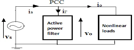
[image:1.595.318.550.543.629.2]Over the last few years, active power filters (APFs) have drawn great attention and are expected to be a suitable remedy for the problem. Two main categories of APFs exist: shunt filters and series filters. The shunt filters are effective for those nonlinear loads, which can be considered as current harmonic sources. Shunt filters are therefore used to generate harmonic currents to compensate load harmonic currents. Series filters are effective to generate harmonic voltages to compensate load harmonic voltages. In this paper shunt active power filters (APFs) are used [3]. APFs are the circuits which are based on switched power semiconductors that inject opposite phase harmonic currents at the point of common coupling (PCC). This results in the whole nonlinear load and APF system matching a nearly resistive load behavior at the PCC terminals.
© 2015, IRJET.NET- All Rights Reserved
Page 1167
objective. Modulation signals to the inverter powersection are generated by the employed controllers. This error can be minimized by two methods they are direct control method and indirect control method. In this project indirect control method is considered as these methods generate the APF current reference indirectly, i.e., by combining the currents of APF and nonlinear-load follow sinusoidal reference current signals in phase with the PCC voltages.
Therefore, using the scheme shown in Fig 1
(1)
Where and are the APF and the PCC reference
currents, respectively, is the non active
[image:2.595.43.282.394.510.2]current component of the mains current is, and represents the load-side current harmonics of order h. Even if the mains voltage presents harmonic distortion, this condition ensures that the correct inverter compensation current will be injected.
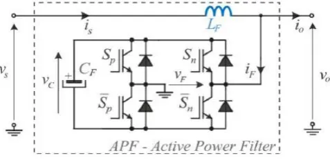
Fig 2: APF architecture used in this work.
Fig.2 shows the active power filter system architecture considered here [4]. The smoothing inductor LF is placed in series with the network and not with the voltage source inverter. The disadvantages of this architecture are that the inductor carries the full load current, except the harmonics, the PCC voltage
v
ois now switched, and due to load current harmonic components the load voltage can be distorted. Another aspect is that the rate of change of the load current is limited by the presence of LF. However, this APF structure implies an advantage from the APF control strategy point. Now the inductor current reference is sinusoidal and in phase with the mains voltage as is the APF modulating signal m(t). Therefore, the inductor current becomes independent from the harmonic currents of the load. It implies that(2)
Where x¯ represents the local average value of x during a
carrier period, is the peak value of the mains voltage and ω1 is the mains voltage angular frequency. The proposed control strategy is much simpler to implement.
2.
CURRENT CONTROL TECHNIQUES
There are two types of current control
techniques they are direct current control technique and indirect current control technique. The difference between these two types of current control technique is in the number of current sensors used. For both the schemes a simple PI-controller is used to obtain reference current templates. Active power filter using indirect current control technique did not need compensation current measurement, but only detection devices for power supply voltage, power supply current and DC voltage. Compared with direct current control technique the indirect current controlled active power filter has simpler system structure and better harmonic treating performances. Therefore, such technique can effectively reduce system requirement for the hardware environment and is easy to implement with DSP technique.
A multiresonant controller is made of a set of resonant controllers, each tuned at a specific resonant frequency. The inverter is controlled by a multiresonant current controller. Resonant controller would be a good alternative, if it can satisfy the dual functions of regulation and selectivity. For the first function of current regulation, the resonant controller is sufficient to fulfill the task. The basic functionality of the PR controller is to introduce an infinite gain at a selected resonant frequency for eliminating steady state error at that frequency, and is therefore conceptually similar to an integrator whose infinite DC gain forces the DC steady-state error to zero. PR controllers have excellent current regulation performance for selected harmonics because large gain is assured for the resonant frequency. With the introduced flexibility of tuning the resonant frequency, attempts at using multiple PR controllers[5] for selectively compensating low-order harmonics. Another advantage associated with the PR controllers and filters is the possibility of implementing selective harmonic compensation without requiring excessive computational resources. With regard that selectivity is the most significant feature of controller.
© 2015, IRJET.NET- All Rights Reserved
Page 1168
PWM current controller to produce the switching signalsfor the inverter switches or it can be fed to a PI controller, to reduce it to an acceptable value. Now it is compared with a triangular carrier to produce the PWM signals. The design of filter inductance fLis based on the
current control technique used for generation of the switching pulse for the converter switches. In this work, carrier phase shifted PWM technique is used, in which two triangular signals will be compared with the generated reference signal. Total harmonic distortion has been improved. The important thing in APF is to maintain the capacitor voltage as constant [6]. For this, the capacitor voltage will be compared with a reference voltage and error signal will be processed through a PI controller through which capacitor voltage can be made constant.
3. CONTROL STRATEGY CONCEPTS
The interesting reduction technique of current harmonic is PWM rectifier. The PWM rectifier provides DC bus voltage stabilization and also acts as active line conditioner(ALC) that compensate harmonics and reactive power at the PCC. Reducing the cost of the PWM rectifier is important. The cost of power switching devices (e.g. IGBT) and digital signal processors (DSP.s) are decreasing and further reduction can be obtained by reducing the number of sensors. The sensorless methods[7] provides advantages to the system as: simplification, improved reliability and lower installation costs.
3.1 Current Sensorless Strategy
In current sensorless strategy reduction of current sensors is carried out. In AC current sensorless the solution is based on inductor voltage measurement in two lines. Supply voltage can be estimated with assumption that voltage on inductance is equal to line voltage. Applying Kirchhoff’s second law to the circuit in Fig. 2 gives
(3)
Where and are the switching functions for switches Sp and Sn, respectively. These are defined as +1 if a switch is closed and 0 when it is open. The resulting switching function for the filter comprehends both of
these into . The switching signals are
generated by phase-shifted pulse width modulation. The high-frequency (HF) harmonics are typically eliminated with filters, and the following analysis considers only the low-frequency behavior of the circuit. This is achieved with the definition of the local average value x¯ of the
quantities within a switching period Ts. Applying this definition to the APF switching function leads to
(4)
where is the resulting APF duty cycle. This has to be generated by the control strategy. The result obtained when (4) is applied to (3) is
(5)
Assuming that a unity input power factor is to be achieved, the system should emulate a nearly resistive behavior. Thus
(6)
Where is the desired resistance value. The APF dc-link voltage is controlled with a variable vm. This is defined as
(7)
Where k is the gain and is the dc-link voltage reference. Isolating in (7) and using it in (5) gives
(8)
Assuming a purely sinusoidal leads to
(9)
where ω is the sine angular frequency. The control signal is assumed constant at steady state. Thus, (8) is rewritten as
(10)
Defining
(11)
and replacing it in (9) results in
(12)
© 2015, IRJET.NET- All Rights Reserved
Page 1169
frequency and with reduced current ripple. Theprocedure to determine the duty cycle described earlier is input current sensorless and has the advantage of only measuring the input and the dc-link voltages to generate the control signal.
Fig.3: Block diagram for the current sensorless control strategy based on equation (12)
3.2 Voltage Sensorless Strategy
Similar to input current sensorless strategy, an input voltage sensorless strategy is derived in the following. The dc current control should work effectively when the reference value of the dc current is changed. For that reason, a non-linear PI controller, where the input of the controller is the square of the error signal, is proposed for the control systems. With small error values the controller acts slowly and when the error value is increased faster control dynamics is achieved.
Replacing vs from (6) in (5) gives
(13)
During sinusoidal steady state
(14)
Defining the dc-link voltage control signal as
(15)
Where Rs is the current measurement gain, and substituting the before mentioned relations into (13) lead to
(16)
Defining gain as
(17)
and dividing (16) by Vc* Rs finally gives the duty cycle
(18)
The voltage sensorless control strategy [8] based on (18) is implemented with the block diagram shown in Fig. 4.
Fig.4: Block diagram for the voltage sensorless control based on equation (18).
The strategy is straightforward and similar from the practical implementation aspects to the current sensorless one. The advantage of this approach over the current sensorless one is that over current protection techniques are easier to implement with the current measurement.
4. FUZZY LOGIC
© 2015, IRJET.NET- All Rights Reserved
Page 1170
effective tool for the conception and design of intelligentsystems. The fuzzy logic toolbox is easy to implement and convenient to use. It provides a reader friendly and up-to-date introduction to methodology of fuzzy logic and its wide ranging applications.
4.1 Fuzzy Logic Controllers
[image:5.595.37.286.383.508.2]The word Fuzzy means vagueness. Fuzziness occurs when the boundary of piece of information is not clear-cut. In 1965 Lotfi A.Zahed propounded the fuzzy set theory. Fuzzy set theory exhibits great potential for effective solving of the uncertainty in the problem. Fuzzy set theory is an excellent mathematical tool to handle the uncertainty arising due to vagueness. Understanding human speech and recognizing handwritten characters are some common instances where fuzziness manifests. Fuzzy set theory is an extension of classical set theory where elements have varying degrees of membership. In FLC the input variables are mapped by sets of membership functions and these are called as “FUZZY SETS”. Fig.5 shows basic FUZZY module.
Fig.5: Fuzzy Basic Module
Table 1: Control strategy based on 49 Fuzzy control Rules with combination of seven error states multiplying with
seven changes of error states.
Fuzzy set comprises from a membership function which could be defines by parameters. The value between 0 and 1 reveals a degree of membership to the fuzzy set. The process of converting the crisp input to a fuzzy value is called as “fuzzificaton [9].” The output of the Fuzzier module is interfaced with the rules. The basic operation of FLC is constructed from fuzzy control rules utilizing the values of fuzzy sets in general for the error and the change of error and control action. The results are combined to give a crisp output controlling the output variable and this process is called as the “DEFUZZIFICATION.”
The PI controller in Fig.3 and Fig.4 are replaced with FUZZY controller and results are observed. The results are improved when fuzzy controller is connected. The THD values are reduced.
5. SIMULATION RESULTS
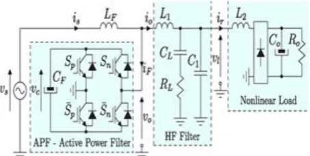
The power stage configuration used in the simulation-based analysis of the APF system is shown in Fig. 6. A low APF switching frequency of fc = 5 kHz is used to highlight the performance of the proposed concepts. The nonlinear load is a single-phase diode bridge rectifier with the following parameters:
Ro = 40 Ω, Co = 940 μF, L2 = 1 mH.
Fig.6: APF power stage setup used in the simulation results
Other experimental parameters are as follows: Input ac voltage is set to Vs,rms = 110 V, Main frequency fs = 60 Hz,
APF inductance LF = 12.83 mF, HF filter inductance L1 =1.4 mH, HF filter resistance RL = 2 Ω, HF filter capacitance CL = 8 μF, and HF filter capacitance C1 = 0 μF e/de NB NM NS Z PS PM PB
NB NB NB NB NB NB NB NB
NM NB NM NM NM NS NS NS
NS NB NM NM NS NS NS Z
Z Z Z Z Z Z Z Z
PS Z PS PS PS PM PM PB
PM PS PS PS PM PM PB PB
[image:5.595.321.548.478.592.2]© 2015, IRJET.NET- All Rights Reserved
Page 1171
The simulation results are shown in Figs. (7)and (8) for the voltage sensorless control strategy with PI and in Figs. (12) and (13) with FUZZY controllers. The Mains current Is , APF control variable dF and the Load
voltage Vl are shown in Fig.(8) for PI controller and in
Fig.(13) for FUZZY controller . The mains current shown in Fig. 8, is in phase with the mains voltage despite the large filter inductance of LF = 12.83 mH. Thus, it proves the capability of the novel APF concept to emulate a resistive behavior when observed from the mains. Finally, Fig .8, shows the APF duty cycle and the load voltage at the terminals of the CL−RL branch with the respective THD value of 9.65%. When PI controller is replaced with FUZZY controller the exact error percentage can be obtained and distortions can be reduced. The THD value of load voltage obtained with FUZZY controller is 4.81%
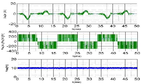
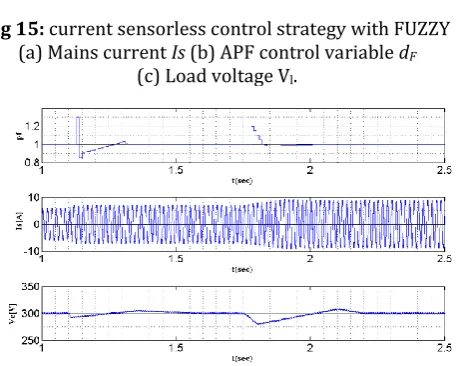
Similar results are found for the current sensorless control strategy as seen in the respective graphs shown in Figs.(9) and (10) with PI and in Figs,(14) and(15) with FUZZY controller . Fig. 10, shows the load voltage at the terminals of the CL−RL branch with the respective THD value of 9.83%. It can be seen that harmonic distortion appears as the load current causes a distorted voltage across inductor L1, which is partially filtered with the parallel branch RL−CL. This effect should be analyzed on a case-based approach in order to evaluate the load voltage. Reducing inductor L1, increasing CL, and/or including capacitance C1 reduces the load voltage distortion. When PI controller is replaced with FUZZY controller the distortions can be reduced. The THD value of load voltage obtained with FUZZY controller is 4.86%
In order to compare the transient performances of the current sensorless control strategies, a simulation with the same conditions including an input voltage step at t = 1.1 s from 100% to 120% of rated voltage and a load step from 75% to 100% of rated power at t = 1.75 s was carried out. The result for the power factor variation during load change is shown in Fig. 11. As it is very difficult to observe the differences in the mains current, a variable related to the power factor is used. This local power factor variable is defined as
(19)
Where is the mains fundamental period. It gives the correct power factor at steady state and an impression of the power deviations during transients. Fig. 11, shows that the combined method gives shorter transients and that both methods achieve close-to-unity power factor at
[image:6.595.331.558.285.415.2]steady state for all tested load conditions. Both control strategies have presented similar results regarding the mains-side current is and the APF dc-link voltage vc, which are exemplarily shown in Fig. 11. The settling time was below 1 s for the given simulation conditions and is mainly dictated by the APF dc-link voltage control loop. The simulation results during an input voltage transient at t = 1.1 s from 100% to 120% of rated voltage and a load transient from 75% to 100% of rated power at t = 1.75s for the current sensorless control strategy with PI and FUZZY controllers are shown in Figs. (11) and (16). The THD value of when PI controller is connected during load change is 3.09% and when FUZZY controller is connected is 1.56%.
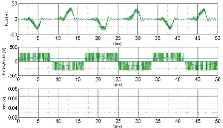
Fig 7: voltage sensorless control strategy with PI a) Load-side PCC current Io and rectifier current Ir. (b) APF capacitor voltage Vc, APF output voltage Vo, and
mains voltage vs. (c) DC link control variable Vm.
Fig 8: voltage sensorless control strategy with PI (a) Mains current Is (b) APF control variable dF
© 2015, IRJET.NET- All Rights Reserved
Page 1172
Fig 9: current sensorless control strategy with PIa) Load-side PCC current Io and rectifier current Ir. (b) APF capacitor voltage Vc APF output voltage Vo, and
mains voltage Vs. (c) DC link control variable Vm.
Fig 10: current sensorless control strategy with PI (a) Mains current is (b) APF control variable dF
[image:7.595.321.552.120.251.2](c) Load voltage Vl.
Fig.11: Simulation result waveforms for the current sensorless indirect control strategy with PI (a) Local power factor value according to (19). (b) Mains current is. (c) APF capacitor voltage Vc
[image:7.595.51.277.121.259.2]during load change
Fig 12: voltage sensorless control strategy with FUZZY a) Load-side PCC current Io and rectifier current Ir. (b) APF capacitor voltage Vc, APF output voltage Vo, and
[image:7.595.319.556.281.446.2]mains voltage vs. (c) DC link control variable Vm.
Fig 13: voltage sensorless control strategy with FUZZY (a) Mains current is (b) APF control variable dF
(c) Load voltage Vl.
Fig 14: current sensorless control strategy with FUZZY a) Load-side PCC current Io and rectifier current Ir. (b) APF capacitor voltage Vc, APF output voltage Vo, and
[image:7.595.320.558.500.642.2]© 2015, IRJET.NET- All Rights Reserved
Page 1173
Fig 15: current sensorless control strategy with FUZZY(a) Mains current Is (b) APF control variable dF
(c) Load voltage Vl.
Fig.16: Simulation result waveforms for the current sensorless indirect control strategy with FUZZY
(a) Local power factor value according to (19). (b) Mains current Is. (c) APF capacitor voltage
V
cduring load change
6. CONCLUSIONS
Control strategies for shunt APF architecture have been proposed here. The proposed strategies were able to guarantee close-to-unity power factor. Both current and voltage sensorless versions have been presented, where the current sensorless control has been analyzed in detail regarding its performance and equivalent circuits with PI and FUZZY controllers. The implicit control loop is another innovative characteristic. These characteristics were verified through circuit simulation including a nonlinear rectifier load. This is a very low switching and highlights the achievable performance. The THD values are reduced when FUZZY controller is connected compared with PI controller. The concepts can be easily extended to the control of PFC rectifiers and three –phase systems.
REFERENCES
[1] P. Salmeron and S. Litran, “Improvement of the electric power quality using series active and shunt passive filters,” IEEE Trans. Power Del., vol. 25, no. 2, pp. 1058–1067, Apr.2010.
[2] H. Akagi, A. Nabae, and S. Atoh, “Control strategy of active power filters using multiple voltage-source PWM converters,” IEEE Trans. Ind. Appl., vol. IA-22, no. 3, pp. 460–465,May1986.
[3] Y. Tang, P. C. Loh, P. Wang, F. H. Choo, F. Gao, and F. Blaabjerg, “Generalized design of high performance shunt active power filter with output LCL filter,” IEEE Trans. Ind. Electron., vol. 59, no. 3, pp. 1443–1452, Mar. 2012.
[4] G.-Y. Jeong, T.-J. Park, and B.-H. Kwon, “Line-voltage-sensorless ac tive power filter for reactive power compensation,” Proc. Inst. Elect. Eng.—Elect. Power Appl., vol. 147, no. 5, pp. 385–390, Sep. 2000.
[5].R. Teodorescu, F. Blaabjerg, M. Liserre, and P. C. Loh, “Proportional resonant controllers and filters for grid-connected voltage-source converters,”Proc. Inst. Elect. Eng.—Elect. Power Appl., vol. 153, no. 5, pp. 750–762, Sep. 2006.
[6] A. Bhattacharya and C. Chakraborty, “A shunt active power filter with enhanced performance using ANN-based predictive and adaptive controllers,”IEEE Trans. Ind. Electron., vol. 58, no. 2, pp. 421–428,Feb. 2011.
[7] M. Salo, “AC current sensorless control of the current-source active power filter,” in Proc. IEEE 36th PESC, Jun. 2005, pp. 2603–2608.
[8] Mauricio Angulo, Domingo A. Ruiz-Caballero, “Active Power Filter Control Strategy With Implicit
Closed-Loop Current Control and Resonant Controller” IEEE transactions on ind. Electron., vol. 60, no. 7,pp. 2721-2730, july. 2013
[image:8.595.49.278.252.435.2]© 2015, IRJET.NET- All Rights Reserved
Page 1174
BIOGRAPHIES
K. Naga Viswaja currently
pursuing M.Tech in Electrical Power Systems at JNTUA College of Engineering and Technology Anantapur, Andhra Pradesh. Her area of interest is Power Systems.