ANALYSIS OF OPTIMAL LOCATION OF SUPERCONDUCTING FAULT
CURRENT LIMITER FOR THE SMART GRID
Rohini A. Desai1, Mangesh R. Bongale2 and H. T. Jadhav1 1Department of Electrical Engineering Rajarambapu Institute of Technology Sangli, India 2Department of Electrical Engineering Veermata Jijabai Technological Institute, Mumbai, India
E-Mail: [email protected]
ABSTRACT
In today’s world, smart grid is the new term used for future power system. Also, there is dramatic growth in power system and interconnected network. Due to this increased interconnected network possibility of occurrence of abnormal events is more, which may harm the physical equipments in power system. Use of Superconducting fault current limiter is an effective solution to avoid these problems. Superconducting fault current limiter is an innovative protection device which is used to reduce the magnitude of fault current in high voltage system. In this paper the application of resistive type superconducting fault current limiter is explained, which is used to reduce the magnitude of fault current in designed smart grid system. However, Finding optimal location for installation of superconducting fault current limiter is difficult task. This paper describes a study on performance analysis of smart grid with superconducting fault current limiter and its optimal location.
Keywords: fault current limiter, superconducting fault current limiter, micro grid, smart grid, resistive SFCL- Matlab/ Simulink.
1. INTRODUCTION
Nowadays there is increase of power generation due to growing power demand and increased interconnected networks, can cause large magnitude of fault current to flow through the power system network. This growth is expected to continue in future. When there is occurrence of an accidental events like lightning or downed power lines, a large amount of power flows through the grid which results in a failure of the electric system. Therefore protection of the system is an important consideration to avoid harm to the system parameters and system equipments from large amount of current during fault [16], [19].
Conventional protection devices used for protection of high voltage power system are Circuit Breakers tripped by over current relay, which require first two or three cycles to pass through, to get activated. An alternative to all the above conventional devices is superconducting fault current limiter, which has capability to reduce magnitude of fault current within first cycle of fault, results in increased transient stability of the power system[19].
Smart grid is the modernized electrical grid which uses modern communication technology and renewable energy sources for future power grid, results in increased reliability, cleanliness and decreased response time than conventional power system [12]-[14].
Smart grid networks are decentralized into a small network known as micro grids. Distributed generation are connected with microgrids. However, this integration may cause some serious problems like increase in magnitude of fault current and islanding. i.e. when there is occurance of fault, current get increased which may
harm the system equipments. DG continues the power supply to the faulty network, known as islanding [12].
Many studies have been carried out on, application of SFCL in electrical power system and fault current issues in smart grid. Hence solving the problems related with fault current in micro grid is the main concern of this work. However, to connect SFCL in an electric power grid, following factors must be considered,
Optimal location to install SFCL
Protective Co-ordination problem with other
protective devices.
Recently there is a significant progress in Research and Development of SFCL. This paper focuses on finding out the optimal location for installation of SFCL in a micro grid [6].
2. TECHNOLOGIES
A. Non-Superconducting
Fault Current Limiters that do not depend on Superconducting materials to perform the current limiting action. It contains current limiting fuses, solid-state devices & many other [4].
B. Superconducting
3. SIMULATION MODEL
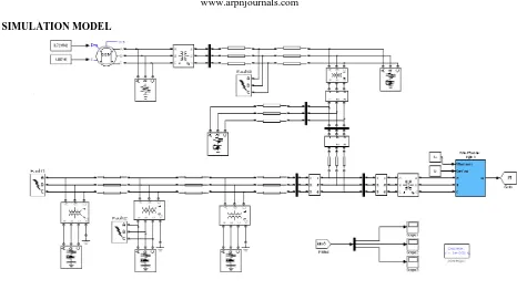
Figure-1. Power System Model designed in Matlab/ Simulink/ SimPowerSystem.
A. Power System Model
A microgrid integrated with 10MVA wind farm is designed in Matlab/Simulink/SimPowerSystem as shown in Figure-1.This power system model consists of conventional power plant and 3-ph synchronous machine 100MVA rating. Distributed parameter transmission line of 200km is used to connect this 10MVA plant, through step-up transformer TR1.TR2 is used to step down voltage from 154kv to 22.9kv at substation.There are industrial and domestic loads supplied from separate distribution network. Domestic loads are supplied by 10MVA wind farm.
In this power system model, location of SFCL and faults are shown. SFCLs are located at location 1,2,3 and 4. Faults are indicated as fault1,fault2 and fault3. These artificial faults are created in distribution grid,customer grid and transmission grid. SFCL is placed at Location1 is at substation, Location2 at branch network, Location3 at wind farm and grid integration point. Location4 is at wind farm.Output current of wind farm is measured and analyzed for different SFCL location.
B. Resistive SFCL Model
Resistive model of SFCL is designed in Matlab/Simulink/ Sim Power System as shown in Figure-2. Four fundamental parameters are used to design the resistive SFCL are as below,
1. Transition time
2. Minimum and Maximum Impedance
3. Triggering time
4. Recovery time
[image:2.612.320.536.371.445.2]Figure-4 shows the simulation model of resistive SFCL.
Figure-2. SFCL model in Simulink.
At first, model measures the Rms value of current, which is then compared with the charactiristic table as in Figure-2. From that the model decides level of impedance of SFCL, whether it goes minimum or maximum. Resistance remains minimum, if the rms value of passing current is below its triggering current level and if that value of current exceeds triggering current, its resistance reaches to the maximum impedance level. First order filter is used to reduce the harmonics. Controlled voltage source is used to compensate the voltage sag caused due to the induced fault current.
4.RESULTSANDDISCUSSIONS
The four possible locations for SFCL installation were analyzed for three different fault locations. At first single SFCL located at substation. Second, single SFCL located at branch network. Third, single SFCL located in between wind farm and grid. Fourth, two SFCL located, one at, substation and another at wind farm.
A. Fault 1: Distribution grid
location 1 and location 2 fault current magnitude get increased than magnitude in normal system. In case of SFCL located at location 3, magnitude of fault current reduced successfully. When two SFCL located at location 1 and 4, fault current magnitude is reduced but it is not economically and technically feasible option.
Figure-3. Comparision of wind farm fault current for
different SFCL locations when fault is in distribution grid.
B. Fault 2: Customer grid
Figure-4 shows a comparison of wind farm fault current for different SFCL locations with respect to time, when fault is in customer grid. Magnitude of fault is small in case of fault in customer grid. Results are nearly equal to the results obtained for fault in distribution grid.
Figure-4. Comparision of wind farm fault current for
different SFCL locations when fault is in customer grid.
C. Fault 3: Transmission line
Figure-5 shows a comparison of wind farm fault current for different SFCL locations when fault is in transmission grid. Fault current in this case is very large. In contrast to above two results, SFCL located at location 1 and location 2 reduces the fault current. Result for the SFCL located at location 3 are nearly same as that of SFCL at location 1. Maximum reduction in fault current is obtained, when dual SFCL is located at location 1 and 4.
Figure-5. Comparision of wind farm fault current for
different SFCL locations when fault is in transmission line.
5. CONCLUSIONS
In this paper the application of resistive type superconducting fault current limiter is explained, which is used to reduce the magnitude of fault current in smart grid system designed in Matlab/ Simulink.
The feasibility analysis of positioning of SFCL in modern power grid is presented in this paper. A complete power system, integrated with wind farm is modeled and transient analysis for artificial faults at different locations of the grid is performed, with SFCL at different locations in a grid. This placement of SFCL should be proper. Installation of multiple SFCLs in power grid will be inefficient and costly. Therefore, from the analysis it is observed that, the point of integration of wind farm with power grid will be the suitable location for installation of SFCL, where it can perform efficiently and limit the maximum amount of current
REFERENCES
[1] S. Sugimoto., J. Kida., H. Arita., C. Fakui. Principle and characteristics of a fault current limiter with series compensation. IEEE Trans. Power delivery, vol. 11, no. 2, pp. 842-847, Apr. 1996.
[2] M. Sjostrom., R. Cherkaoui. Enhancement of power system transient stability using superconducting fault current limiters. IEEE Trans. On applied supercond. vol.9, no. 2, June 1999.
[3] L. Dessaint., K. Al-Haddad., H. Le-Huy., G. Sybille. A power system tool based on simulink. IEEE Trans. Industrial Electron, vol. 46, no. 6, pp. 1252-1254, Dec. 1999.
[5] L. Ye., L. Lin., K. P. Juengst. Application studies of superconducting fault current limiters in electric
power systems. IEEE Trans. Appl. supercond., vol.
12, no. 1, Mar. 2002.
[6] K. Hongesombut., Y. Mitani., K. Tsuji. Optimal location assignment and design of superconducting fault current limiters applied to loop power systems. IEEE Trans. on applied supercond. vol. 13, no.2, June 2003.
[7] B. Sung., D. Park., T. Ko. Study on optimal location of a resistive SFCL applied to an electric power grid. IEEE Trans. On applied supercond. vol.13, no. 2, June 2003.
[8] V. Sokolovsky., V. Meerovich., I. Vajda. Superconducting FCL: Design and Application. IEEE Trans. On applied Supercond. vol.14, no.3, Sept. 2004.
[9] V. Sokolovsky., V. Meerovich., I. Vajda. Superconducting FCL: Design and Application. IEEE Trans. On applied Supercond. vol.14, no.3, Sept. 2004.
[10] K. Maki., S. Repo., P. Jarventausta. Effect of wind power based distributed generation on protection of distribution network. IEEE developments in power system protection. vol. 1, pp. 327-330, Dec. 2004.
[11] G. Tang., M.R. Iravani. Aplication of fault current limiter to Minimize Distributed Generation Impact on Coordinated Relay Protection. IEEE International Conf. on power system Transients, Canada, June 2005.
[12] J. Dreisen., P. Vermeyen., R. Belmans. Protection issues in microgrids with multiple distributed generation units. in power conversion Conf., Nagoya, pp. 646-653. , April 2007.
[13] Y. Shirai., K. Furushiba., Y. shouno. Improvement of Power System Stability by Use of Superconducting Fault Current Limiter with ZnO Device and Resistor in parallel. IEEE Trans. On applied Supercond. vol. 18, no. 2, June 2008.
[14] W. Friedl., L. Fickert., E. Schmautzer. Safety and reliability for smart, micro and islanded grids. Presented at the CIRED Seminar: Smart Grids for Distribution, Paper 107, June. 2008.
[15] B. C. Sung., D. K. Park., J. W. Park. Study on a series resistive SFCL to improve power system transient stability: Modeling, Simulation and experimental verification. IEEE Trans. Industrial Electron. vol.56, no.7, pp. 2412-2419, Jul. 2009.
[16] Electric Power Research Institute: Superconducting Fault Current Limiters: Technology Watch 2009, 1017793, Technical Update, December 2009.
[17] Lin Ye., L. Z. Lin. Study of Superconducting Fault Current Limiters for system Integration of Wind Farms. IEEE Trans. On applied Supercond., vol. 20, no. 3, June 2010.
[18] L. Martini., M. Noe. The ECCOFLOW project: Design and simulation results of a superconducting fault current limiter for operation in electricity networks. International Conf. on electricity distribution, June 2011.
[19] Umer A. Khan., J. K. Seong. Feasibility Analysis of the positioning of Superconducting fault current limiters for the smart grid application using simulink and Sim Powersystem. IEEE Trans. on applied Supercond. vol.21, no.3, June 2011.
[20] Steven M. Blair., C. D. Booth. and G. M. Burt. Current-Time Characteristics of Resistive Superconducting Fault current Limiters. IEEE Trans. On applied supercond. Vol.22, No.2, April 2012.
[21] H. P. Kraemer., W. Schmidt., H. Cai.
Superconducting Fault current Limiters for Transmission Voltage. Elsevier, pp.921-926, 2012.
[22] Z. Hong, J. Sheng, “The Development and performance test of a 10KV Resistive type superconducting fault current limiter,” IEEE Trans. on applied Supercond., vol.22, no.3, June 2012.
[23] J. Bock., A. Hobl. Superconducting fault current Limiters-A new device for future smartgrids. International conf. on Electricity Distribution, Sept. 2012.
[24] Soumen Kar., Sandeep Kulkarni. Conceptual design of a 440V/800A Resistive type Superconducting fault current limiter based on High Tc coated conductors. IEEE Trans. on applied Supercond. Vol.22, no.5, October 2012.
[25] Manglesh Dixit., Sunil Kedia. Development of 440V/800A Resistive type modular superconducting fault current limiter with YBCO Tapes. IEEE Trans. on applied Supercond. Vol.23, no.1, Feb 2013.
[27] A. Rama Devi., J. Nani Kumar. Simulation of resistive superconducting fault current limiter and its performance analysis in 3-ph systems. International Journal of Engg. And research. Vol.2, Issue 11, Nov. 2013.
[28] Y. Chen., X. Liu. Design & application of a superconducting fault current limiter in DC systems. IEEE Trans. on applied Supercond. Vol.24, no.5,