C E
~J
T RA L
PROCESSOR UNIT
WCPU68LA
I[1JSTALLATION MANUAL
58009917
DPS
8
MULTICS (FREESTANDING
UN
IT)
This document and tre information contained herein ar~ confidentiai to and the prope,.ty of Honeywell Information S'lstems, Inc. and are made available only to HoneyweJ I employees for the sole purpose of mainta!ning Honeywell's products.
;n,s document, any COpy thereof and the information contained herein shall be maIntaIned in strictest confidence; shall not be copied in ~hole or in part eKceo: as authorized by the employee's manage~; and shail not be disclosed o· d:strlbuted (a) to persons who are not Honeywell employees, or (b) to Honeywell employees for who~ such information is not necessary in connection with their a$si~ned responsibi Ilties. Upon request, or when the employee In possession of thiS do:ument no longer has need for the document for the a~~~orized Honey~ell purpose, this document and any cOPies thereof shat I b~ returned to the emoloyee's manager. There sMal I be no exceptions to the termS and conditIons set forth herein except as authorized in writing by the responsible Honey_ell Vice PreSld~nt.
58009917-040
015T. NCO, XAN
HONEYWELL CONFIDENTIAL
&
PROPRIETARY
REV E
The following nolice is provided in accordance with the Uniled States
Federal Cornnrunications C~ission's CFCC) regulations.
Warning: This equip~nt generales. uses. and can radiale radio frequency
energy and if not installed and used in accordance wilh the instructions
manual. may cause interference to radio connwnicaljons. As te~orari)y
I
permitted by regulation it has not been tested for cQmpI iance with limitsfor Class A co~uting devices pursuant to Subpart J of Part 15 of
rcc
Rules.which are designed lo provide reasonable protection against such
interfer-ence. Operation of this equi~nt in a residential area is likely to cause
interference in which case the user at his own expense will be required to
take whatever ~asures ~y be required to correct the interference.
58009979-018
IFREV DATE
A 9/81
8 2/82
C 7/82
0 6/83
E 8/84
58009917-014
RECORD OF REVISION
AUTHORIZATION PAGES AFFECTED
PHAFPD903 58009917-040
PHAFPD904
PHAFPD918
PHAFPD949
PHAFPD978
58009979-018, IF 58009917-014, IF 58009917-019, IF 58009917-041, IF
58009917-017, 1 Thru 4F 1-1
&
1-2F. 2-1 THRU 2-6F, 3-1 THRU 3-7F, 4-1 THRU 4-11F 5-1 THRU 5-3F58009917-040 58009979-018, IF 58009917-014
58009917, 3-4, 3-4.1 58009917, 4-2
58009917-040 58009917-014 58009917-017 SH3 58009917, 1-1: 1-2F 5800991 7-, 3-2, 3-7F 58009917, 4-5, 4-6, 4-9, 4-10, 4-11F
58009917-040 58009917-014,1F 58009917-041,IF 58009917, 3-1
58009917-040 58009917-014,IF 58009917-041,lF
4-7,
REV E
153009917, 3-1,3-1. i,3-4,3-4.1,3-4.2
A ISSUED
DPS 8 MULTICS
CENTRAL PROCESSOR UNIT
INSTALLATION MANUAL
58009917
PREFACE
This manual has been prepared lo guide and assist you in the
installation. check-out or deinstal Jalion of the DPS
a
MullicsCentral Processor Unit. WCPU68LA.
Contained in this manual are instructions for unpacking.
inspec-tion. cable routing and connections. A power-up and equipment
check-out procedure will help assure correct equipment
opera-tion and efficient performance. Also included in this manual
are deinsta1lation procedures required for safe disconnection and return of the equipment.
58009917-019
IF58009917-041
REV E
o
~
I '
n
00000 0 00I
I : CPU ~ 0 DD
I .
I
~II
I~
E
1
II'~
I
1'---1
0
§
DPS 8 MUlTICS
CENTRAL PROCESSOR UNIT
WCPU68lA
A ISSUED
MANUAL CONTENTS
PAGE NO.
1 .0
1 . 1
1 .2 1 .3 1 .4 1 .5 1 .6
2.0
2 . 1
2.2
2.3 2.4 2.5'2.S·
2.7 2.8GENERAL ... .
I NTRODUCT I ON ... : ... . TOOLS REQU I RED ... . TEST EQU I PMENT REQU I RED ... .
TEST MED I A REQU I RED ... . REFERENCE DOCUMENTA T I ON ... .
FEEDBACK ... .
PRE INSTALLATION ... .
SITE PREPARATION ... .
METHODS OF EQUIPMENT PACKAGING AND CRATING ... . RECE I PT OF EQU I PMENT ... . UNPACKAGING A NON-CRATED PACK ... .
UNPACKING A CRATED PACK ... . UNPACK I
NG ...
~... .
V I SUAL 1 NSPECT ION ... . PLACEMENT OF EQU I PMENT ... .
3.0 INSTALLATION OF THE THE DPS 8 MULTICS
3 . 1
3.2
3.3
3.4 3.5
3.6
CENTRAL PROCESSOR UN
IT ... .
SCOPE ... .
LOCATING THE BASIC ELEMENTS ... .
CPU LOGIC
BOARD LAYOUTTRIM STRIP INSTALLATION ... . GROUND I NG .. '" ... .
POWER ENTRY ... .
4.0 APPLYING POWER TO THE
CPU ..
4.1 PRE-POWER UP INSPECTION 4.2 APPLYING AC POWER
4.3 APPLYING DC POWER 4.4 POWER SHUTDOWN
4.5 POWER SYSTEM CHECKOUT· 4.6 OFFLINE T&D'S
4.7 ONLINE 1&D'S
58009917-017
HONEYWELL CONFIDENTIAL
&
PROPRIETARYMANUAL CONTENTS(CONTINUED)
5.0 DEINSTALLATION
5.1
SITE INSPECTION
5.2 EQUIPMENT INVENTORY.
5.3 DEINSTALLATION PROCEDURE.
5.4 HANDLING AND SHIPPING
58009917-017
HONEYWELL CONFIDENTIAL
& PROPRIETARY
A ISSUED
PAGE NO.
5-1
5-1
5-1
5-2
5-3F
REV C
LIST OF ILLUSTRATIONS
FIGURE NO.
TITLE
PAGE NO.
3-1
DPS
8MULTICS CENTRAL PROCESSOR UNIT
(CPU). WCPU68.LA
...
3-1
3-2
CPU COMPONENT LOCATOR ...
3-2
3-3
CPU LOG I C BOARD LAYOUT ...
3-4
3-4
TRIM STRIP INSTALLATION ...
3-5
3-5
GROUND STRAP INSTALLATION ...
3-6
3-6
POWER ENTRY
...
3-7F
4-1
OPERATOR CONTROL PANEL
(CAB I NET SHUTDOWN SW ITCH)
... .
4-1
4-2
PRIMARY POWER INPUT CIRCUIT BREAKER
AT S02 (OFF POSITION)
... .
4-2
4-3
FANS AND DC REGULATORS CIRCUIT BREAKERS
AT S03 (OFF POSITION) ... .
4-2
4-4
POWER CONTROL MODULE
ATVCl
(MARGINS AND POWER CONTROL SWITCHES) ... .
4-3
4-5
PRIMARY POWER INPUT CIRCUIT BREAKER
AT S02 (ON POSITION) ... .
4~3A _ a
~-v
POWER CONTROL MODULE AT Vel
(AC ON INDICATOR)
... . 4-4
4-7
OPERATOR CONTROL PANEL (AC PRESENT
AND POWER OFF I ND I CATORS)
... .
4-4
4-8
+5V MASTER REGULATOR AT VJ1 (OFF
REMOTE SW ITCH)
... . 4-5
4-9
FANS AND DC REGULATORS CIRCUIT BREAKERS
AT S03 (ON POSITION)
... .
4-5
4-10
POWER CONTROL MODULE AT vel
(POWER-ON SW ITCH) ... .
4-6
4-11
CONFIGURATION PANEL
4-6
I
4-12
4-13
OPERATOR CONTROL PANEL (POWER OFF
AND POWER ON INDICATORS)
... .
POWER CONTROL MODULE AT VCl
(DC CONF. DC ON AND TEMP I ND I CATORS) ... .
4-6
I
4-7
58009917"':017
[image:8.612.75.562.108.700.2]LIST OF ILLUSTRATIONS (CONTINUED)
FIGURE NO.
4-14
4-15
4-16
4-17
4-18
4-19
58009917-017
TITLE
OPERATOR CONTROL PANEL (POWER ON
SWITCH) ...
. ... .
PRIMARY POWER INPUT CIRCUIT BREAKER
AT
S02 (OFF POSITION) ... .
OPERATOR CONTROL PANEL (CABINET
SHUTDOWN SW ITCH) ... .... ..
OPERATOR CONTROL PANEL (POWER OFF
AND POWER ON INDICATORS)
POWER. CONTROL MODULE AT VCl
(DC INDICATORS AND SWITCHES)
FANS AND DC REGULATORS CIRCUIT
BREAKERS AT S03(5LO BLO FUSES).·
HONEYWELL CONFIDENTIAL
& PROPRIETARY
A ISSUED
PAGE NO.
4-8
4-8
4-9
4-10
4-10
4-11F'
REV C
1 .0
GENER·AL
1 .
1
I NTRODUCT ION
This manual has been prepared to serve as an aid fOT installing
the DPS 8 Central Processor Unit. WCPU68LA. Infonnation for site
planning and preparation is contained in the Site Preparation
Manual.DNO!. A copy of the Site Preparation Manual and the
Customer Site Layout Plan. should be obtained from the Honeywell
Site Manager prior to installation. Refer to the DPS 8 Multics
Central Processor Options Manual. 58009912. for options installation.
1.2
TOOLS REQUIRED
Standard Hand Tools including:
• Hex Wrench 4rnm (58020343-002)
1.3
TEST EQUIPMENT REQUIRED
Standard Test Equip~nl
1.4
TEST
MEQIA
REQUIRED
~ Off=]ine T&D System Tape{PAS 2/Moniior)
I
58009917
REV C
1 .5
REFERENCE DOCUMENTATION
In addition to the test ~dja. the following doc~nts will provide installation and checkout aids.
•
Site Layout Plan Provided•
Site Preparation Manual Later • S Y stem Man u a 1 ... . 58009906•
Packaging Specification 58067223•
System Operating Techniques DD50•
Maintenance Operation Manual (MOM) 58009927 • DPS 8 Mu] tics CPU Options Installation ManuaJ. ... . 58009912 • DPS 8 Mu 1 tic s CPU Un i t Manua 1 •...•...•...•... 58009907•
Power and Coo 1 i ng At'anua 1 Later•
Test'and Repair Manual 58009928 • Series 6000 Test. and Diagnostics Manual ... . 58008382 • Integrated Firmware and Diagnostics Manual ... . 580099781 . 6
FEEDBACK
· I nor d e r t 0 rna i n t a i nth i s rna n u a 1 a s a fun c t ion a l. top ice. ) and
accurate document. please submit co~nts through the normal technical support channels. by utilizing the System Technicai A c 1 ion R e que s t ( S TAR) s Y stem. or rna i I c omne n t s d ire c t 1 y to:
58009917
Honeywell Large Systems Product Support P. O. Box 6000. MS K92
Phoenix. Arizona 85005
HONEYWELL CONFIDENTIAL
& PROPRIETARY
by FED
A ISSUED
2.0
PRE INSTALLATION
This seclion provides the preinstallalion procedures for the installation of a DPS 8 Mullics Central Processor Unil. WCPU68LA. It includes procedures for receiving. handling. uncrating/unpacking.
inspecting and pIecing the equjp~nt.
2.1
SITE PREPARATION
The Field Engineering Representative (FER) should ensure that the customer is prepared to receive and install the equipment.
2.2
METHODS OF EQUIPMENT PACKAGING AND
CRATING
The Central Processor Unii may be shipped in a plastic wrapper
for domestic shipments or crated" for export shipments. See
Packaging Specification 58067223 for detailed packaging instruc-tions.
Uncrated units are shipped in an upright position. protected
by four wooden corner assemblies and strapped plastic wrapping.
Crated units are also shipped in an upright position.
A ISSUED
2.3
RECEIPT OF EQUIPMENT
Up 0 n a r r j v e. 1 0 f the e qui pme n t a t 1 h e sit e. l h e Fie 1 dEn gin e e r j n g
Representative (FER) should assist the customer in receiving.
inventorying. checking for any external d~ge. and directing the
placement of the equipment. Usually the carrier will unload the
equipment and move it to a specified location inside the building. All plastic covers should be renroved as soon as possible to
pre-vent moisture formation in the equjp~nl.
ICAUTION/
THE MASS STORAGE PROCESSOR MUST
BEUNLOADED AND HANDLED WITH CARE TO
AVOID DAMAGE TO THE EQUIPMENT. THIS
UNIT MAY WEIGH IN EXCESS OF 1000 LBS.
1. P rio r t o r e c e i p t 0 f e qui pme n t. the FER s h 0 u J d ass u r e t hat the
customer obtains shipping documents (Bi J] of Lading. Memorandum
of Shipment) from lhe carrier.
2. Up 0 n del i v e r y 0 r 1 h e e qui pme n t. the FER s h 0 u I d ass u r e t hat the
customer invenlories equipment against shipping docmnents (Bi 11
of Lading and Memorandwn of Shipment).
NOTE
The customer representative should be advised not to sign papers at this time.
3. Check wrapping. crating. and cartons for breaks. tears or other evidence of rough handling or damage.
4. The c u s tome r rep res e n tat j v e s h 0 u 1 d not e any los s. d arna g e .
~isture. corrosion and mishandling of equipment on shipping
docwnents before Signing for equipment. and the Field Engineering Representative should so note on lhe Traffic Service Evaluation Report.
5. The FER should assure that the customer nolifies the Honeywel 1
T r a f f i c Man age r 0 fan y los S 0 for d arna g e t o· 1 he e qui pme n t . The
notification may be performed through norma] telephone contact. but must be promptly confirmed in writing to the HoneyweJ) Traffic
Manager. Refer to the Bi) 1 of Lading for the current telephone
number.
58009917
A ISSUED
204
UNPACKAGING A NON-CRATED PACK
Unpackaging is ordinari Jy the smne for any of the DPS
a
Freestandingcabinets packaged in a non-crated pack. The carrier will normally
unpeckage lhe equip~nt per the following steps and set i t in the
specified area.
NOTE
The packaging is.made of strapped plastic wrapping protected with wooden corner
ass emb J i e s . No a t temp t s h 0 u 1 d be rna d e t 0
open the packaging by cutting or prying.
BEFORE REMOVING ANY METAL BINDING STRAPS.
ENSURE THAT NO ONE IS NEAR THE EQUIPMENT
(EXCEPT THE INDIVIDUAL WHO IS REMOVING
THE BINDING STRAPS).
WHEN
CUT.
THESE
STRAPS MAY SPRING FREE. STRIKING ANY
CLOSE OBJECT.
1. Cut external vertical and horizontal binding straps. This
action frees the four corner protectors and top spreaders.
2. Remove the plastic wrapping.
3. Remove lhe wooden corner assemblies which are bolted to
the equip~nl frmne.
4. Aruninislratively dispose of any packaging material.
58009917
A ISSUED
2.5
UNPACKAGING A CRATED PACK
Unpackaging crated cabinets is ordinari ly the smne for any of the
DPS 8 Freestanding cabinets. The carrier wi) I normally unpack age
the equip~nt per lhe following steps and set it in the specified area.
NOTE
The crates are made of cleated wood and/or
J&ninated paper and wood construction. No
alte~t should be made to cut or pry crales apart.
BEFORE REMOVING ANY METAL BINDING STRAPS.
ENSURE THAT NO ONE IS NEAR THE CRATE
(EXCEPT THE INDIVIDUAL WHO IS REMOVING
THE STRAPS).
WHEN CUT. THESE STRAPS MAY
SPRING FREE STRIKING ANY CLOSE OBJECT.
1. Cul external vertical and horizonlal melal binding straps
from crate.
2 . R erne vet heme 1 a l b 0 J 1 s from the fro n t pan e l o r 1 h e c rat e .
3.
Check for and remove any other bolls or nails thal may be in the pane].
Re~o .... e lower edge
or
craie.4 . L i f t c rat e t 0 c) ear cab i net and r emo v e i 1 from p a ] I e 1 .
5. Cut interior vertical and horizontal binding straps. This
aclion frees the cabinet from the base of the crate.
58009917
A ISSUED
6. Remove cabinet from pa1let with a fork lift or hojsl,
being careful to avoid dmnage to the cabinet.
7. Re~ve remaining straps. p]aslic wrap and other packing material from the cabinet.
8. Administratively dispose of any crating material.
2.6
UNPACKING
Unpacking is ordinarily the smne for any of the DPS 8 Freestanding
e qui pme n t . The car r j e r w i J I norma J I Y un pac k the e qui pme n t .
NOTE
Unpacking refers to the removal of any material. including special brackets or devices. which has been placed within the equipment to provide
pro tec t jon from sh i pp i ng/hand ling hazards. A I]
packing material must·be removed from lhe equip-ment.
Ensure that the equipmenl is unpacked as required. Refer Lo the
Packaging Specification. 58067223 for additional information. Administratively dispose of any packing material.
VISUAL INSPECTION
After the equipment has been unpacked. it should again be inspected for physical dmnage and moislure condensation.
C omp let e the
r
0 1 i 0 win g . s l e p s :J. Check the equipmenl for denls in doors and cabinets.
broken indicators and switches. damage to other paris.
missing items and moisture condensation.
58009917
ICAUTIONI
IF MOISTURE IS FOUND. IT SHOULD BE
REMOVED AND THE UNIT ALLOWED TO
STABILIZE IN THE OPERATING
ENVIRON-MENT FOR AT LEAST 24 HOURS.
DURING THE
LAST EIGHT HOURS, AC AND DC POWER SHOULD
BE TURNED ON TO PROMOTE INTERNAL DRYING
BEFORE TESTING.
A ISSUED
2. Have receiver/customer representative record any Joss. concealed
d~age. or corrosion of equipment. on shipping docwnenls.
3. Report any Joss. d~age or corrosion. in writing to the Honeywel)
Traffic Manager.
4. Shipping docwnen1s may now be signed by receiver/cuslo~r
repre-sen1ative.
5. Return Memorandwn of Shipment to HoneyweJ l's General Accounting
Depart~nt a1:
2.8
Honeywell Information Sys1ems P.D.Box 6000
Phoenix. Arizona 85005
c/o Manager. General Accoun1ing
Mai) Station A75
PLACE~ENT
OF EQU1PMENT
. UNCRATED CABINETS SHOULD BE CAREFULLY
MOVED ON THEIR CASTERS TO AVOID
TIPPING THE CABINET OVER.
j . Ensure that the unit has been moved to the operational
ssite and positioned per site layout plan.
300
INSTALLATION OF DPS 8 MULTICS
CENTRAL PROCESSOR UNIT
3.1
SCOPE
REV E
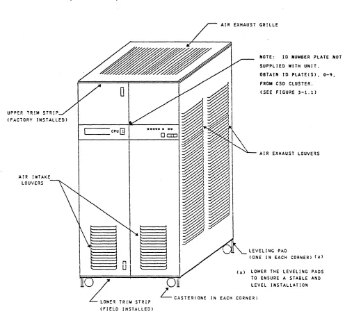
This section provides the procedures to install a DPS 8 Multics Central Processor Unit, WCPUb3LA, referred to hereinafter as the CPU.
UPPER TR!M
ST'IP~
(FACTORY INSTALLED)
'
-AIR INTAKE LOUVERS
o
cpuGj
~E'
TRIM STRIP (FIELD INSTALLED)AIR EXHAUST GRILLE
'\
HOTE: 10 NUMBER PLATE NOT
SUPPLIED WITH UNIT.
OBTAIN 10 PlATE(S), 0-9,
FROM eso CLUSTER. (SEE FIGURE 3-1.1)
~ AIR EXHAUST LOUVERS
LEVELl,.G PAD
(ONE IN EACH CORNER) Ca)
(a) LOWER THE LEVEL I NG PADS
TO ENSURE A STABLE AND
FIGURE 3-1.
DPS 8 MULTIC CENTRAL PROCESSOR UNIT
(CPU), WCPU68LA
I
I
58009917 3-1
[image:18.612.73.569.221.686.2]REV E
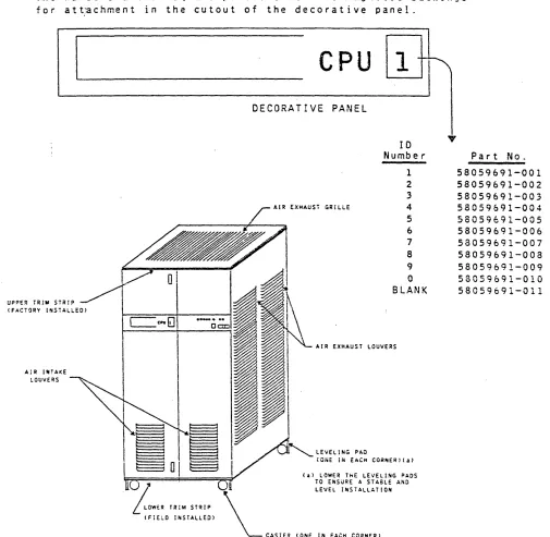
The decorative panel has a cutout for the unit's 10 Number to be installed at the customer's site. The numbers are stocked
at the CSD logistic clusters and must be ordered by the CSR as
required. See part numbers below.
The numbers are on square plates that have magnetic backings for att~chment in the cutout of the decorative panel.
I
AIR If HAKE
tOUVERS
I
58009917
CPU
1
~
DECORATIVE PANEL
10 Number
1 2
3
~iR EXHAUST GRILLE 4
5 6
7
8 9
C
BLANK
AIR EXHAUST LOUVERS
LEvELING PAD
(ONE iN EACH CO~~ERl(a) (a) LOWER ThE LEVELING PADS
TO ENSURE A STABLE AND
LEvEL INSTALLATION
CASTER (ONE IN EACH CORNER)
?
Part No.
58059691-001 58059691-002 58059691-003 58059691-004 58059691-005 58059691-006 58059691-007 58059691-008 58059691-009 58059691-010 58059691-011
FIGURE 3-1.1. CPU
10
NUMBER INSTALLATION
[image:19.612.39.544.179.672.2]y
...,.
..
..
C'''P''C'I'I'OIl J..
_-"..,
z J ~~u(.)
0
-
sun...
..
. . . acuU'l'OllQ:C
•
0 =
..,=
I...
..,0
"
W-...2 sun
~r..w c . . . . ~U?Oll O Z Z
Q:Oc J
...
-
...
A.~G.
..
M8ftIt p . . . U'l'OllI
... --.J
B
REV C
HARNESS ASM 58056786-001 ROUTE LEFT FIE CONN. ON ETCKP
/ A. /
"
I~'
ETCMP ' I
l]]:
• I~._J
Ca). (b)
Tf
1--""10- ~AD
SCOPE GATE
(a).(b)
I
COKFIGURATION PANEL
-HARKESS
?
;0
2' AlI
~z
~ ~
..
. . LT&C& aauU'l'Oll Q.. . /
aoUTE TO BACXPAJlEL LOCATIOKS A3AWK. A3A AND A3AWH_
58009917
,,~
I
•
I...
(a).(b)a::
-..
. . . ~L <.\2
~~ II C'I _a.a I
I ... eea
•
.wT ""1M' ....,1.1k.:
•
. . . J~ . . J•
•
fORD DftT..-ua.aV--•
. . . S-. . I . . "a
•
.\3d
'I§l~
~
:
--..--.kn···mllit
...~
....
~...
'"' ... -...
...
SOl.
...
... ... ...
.-
.
.... ... ...
...
.
[image:20.612.56.572.69.695.2]... .... ...
...
"~IK,...
...
.......
.. ..
.. 6 A4..- '.'::
" .... ~ . . .. .. ..
, , I ,
~U
U1
(a) See Ficure 3-3 for LOlie Board and Harness Cable LoeaL ion •.
(b) For Options Installation see Options Installation Manual, &8008812.
CIRCUIT 8R£AKER MODULE
bOCA'!'!:D A!' 302
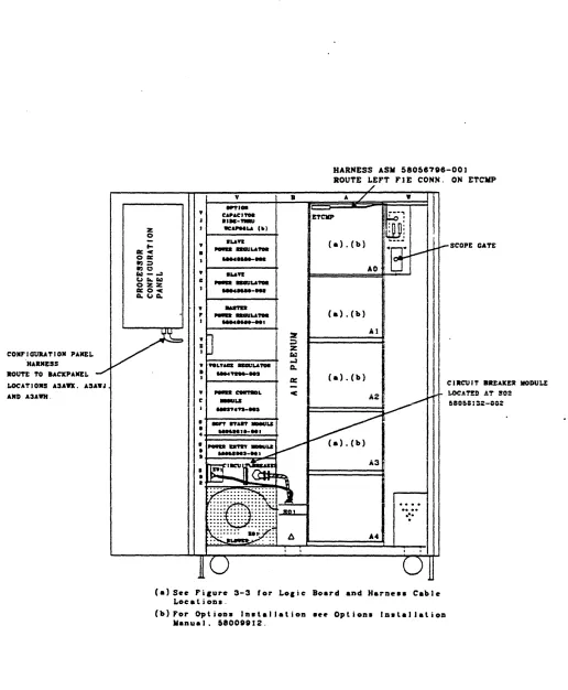
FIGURE 3-2. CPU COMPONENT LOCATOR
A ISSUED
3.2 LOCATING THE BASIC ELEMENTS
The CPU minimwn configuration is shown in Figures 3-2 and 3-3. This configuration includes the following elements.
• Five Logic Board ModuJes located at AO. Al. 'A2. A3 and A4.
• Logic boards as shown in Figure 3-3.
• Power Regulator +5V 180A. 58048580-002. located at VHl.
• Power Regulator +5V 180A. 58048580-002. located at VG1.
• Power Regulator +5V 180A. 58048580-001. located at VFl.
• Voltage Regulator ·lOOW. 58047200-003. located at VOl.
• Power Control Module. 58037473-003. located at Vel.
• Soft Start Module. 58052518-001. located at S04.
• Power Entry Mod~}e. 58052063-002. located at S03.
• Circuit Breaker Module. 58058132-002. located at S02.
• Power Entry Junction Box. located at SOl.
• Configuration Pane] located at Q02 (inside left front door.).'
• Required harnesses and cables as shown in Figures 3-2 and
3-3.
NOTE
For pro per 0 per a t ion 0 f t h j seq u i pme n t. the f 0 J ) 0 win g
options are required:
WIP068LA. Active Port Option
WHCC68LA ... Cache Cab] e Op t ion
Options are installed per the OPS 8 Multics CPU Options Installation Manual. 58009912.
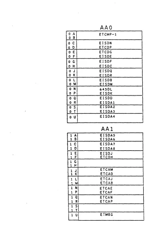
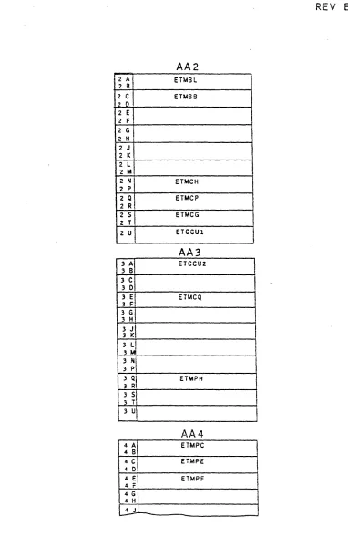
3.3 CPU LOGIC BOARD LAYOUT
The CPU logic board layout is shown jn Fjgure 3-3. Refer to the
CPU Options Installation Manual. 58009912, for the installation of any additional logic boards and harnessing/cabling. associated with the CPU options.
58009917
CPU LOGIC BOARDS CONTAIN CIRCUITS
WHICH MAY BE DAMAGED BY ELECTROSTATIC
DISCHARGE (ESD).
USE PROPER HANDLING
PROCEDURES TO AVOID DAMAGE.
58009917
• C A I
o 8
o C
o 0
o E
o F
o G
o H
OJ'
o K
o L
o M
o N
I
o P
a Q
o R
o S
o T
o U
1 6;
1 C 1 0 1 Ej
1 Fi
1 G'
1 H
1 J
1 K 1 L
I 1 ~! 1 QI 1 R,
AAO
ETCMP-l EISON ETCOP ETCOG EISDE EISDF EISDC EISDQ EISDR ElSDB ElSDM 6450L EISOK EISOO EISOAl EISOA2 EISDA3 EISDA4AAI
EISDA5 EISDA6 EISOA7 EfSDA8 EISOJ ETCDH ETCAM ETCAO ETCAJ ETCA8 ETCAE ETCAF ETCAN ETCAP ETMSGREV E
NOTE: The CPU logic board layout <sheets 1 thru 3}
shows the installation of the CPU boards only.
For CPU options logic board installation, see
the Installation Instructions located in the
CPU Options installation Manual 58009912.
FIGURE 3-3.
CPU LOGIC BOARD LAYOUT (Sheet 1 of 3)
[image:22.612.145.466.64.539.2]REV E
AA2
i 2 A
I
ETMBLZ B
2 C
I
EHA682 0
2 E 2 F
2 G 2 H
2 J
2 K
2 L 2 M
2 N En.tCH
2 p
2 Q ETMCP
2 R
2 S ETMCG 2 T
2 U ETCCUl
AA3
3 A ETCCU2
3 B
3 C
3 0
3 E ETMCQ
3 F I
3 G 3 H
3
J\
3 K3 LI
3 QI
3 R
ETMPH
3 51
pi
AA4
4
~I
ETMPC4 8
4
C\
ETMPE 4 04 EI ETMPF 4 F!
4 G
I
4 H
[image:23.612.129.511.49.638.2]~---~
FIGURE
3-3.
CPU LOGIC BOARD LAYOUT (SHEET 2 OF 3)
REV E
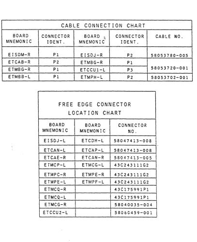
CABLE CONNECTION CHART
BOARD CONNECTOR BOARD ': CONNECTOR CABLE NO. MNEMONIC IDENT. MNEMONIC IDENT.
EISDM-R
I
PI EISDJ-R P2 58053780-00.5 ETCAB-R P2 ETMBG-R PIETMBG-R Pl ETCCUI-L P3 58053720-001 ETMBB-L PI ETMPH-L P2 58053702-001
FREE
EDGE
CONNECTOR
LOCATION
CHART
BOARD
I
BOARD CONNECTOR MNEMONIC I MNEMONIC NC.I
EISDJ-L ETCDH-L 58047413-008 t ETCAN-L ETC"AP-L 58047413-008
I
I
ETCAE-R I ETCAN-R 58047413-005
ETMCP-L ETMCG-L 43C243111G2 ETMPC-R ETMPE-R 43C243111G2 ETMPE-l ETMPF-L 43C243111G2 I
ETMCQ-R 1 4 3C175991Pl ETMCQ-L 43C175991Pl ETMCG-R
i
58040035-004 ETCCU2-L II
58060459-001I
FIGURE 3-3. CPU LOGIC BOARD LAYOUT {SHEET 3F}
HONEYWELL CONFIDENTIAL
&
PROPRIETARY 3 -4 .2I
[image:24.612.120.527.109.609.2]I
I
I
A ISSUED
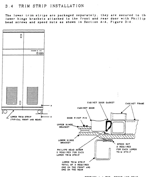
3.4
TRIM STRIP INSTALLATION
ihe lower trim strips are packaged separately. they are secured to the
lower hinge brackets attached Lo Lhe front and rear door with Phil) ips head screws and speed nuts as shown in Section A-A. Figure 3-4.
,
0
0 0 0 0 0 . 00
DOD
I
I
II·
I
II
Inl
j II
ul
;
~
I==no=)==-=-=-===
/==+===o==="='y ..
L
LOWER TR , .. STR I P " - - A CTYPlCAL rRO~T AND REAR)FIGURE 3-4.
58009917
UPPER HINCE
BRACKET --"--.-II~~
LOWER HINCE BRACKET
PHILIPS HEAD SCREW
n
LOWER TRI .. STRIP
~LJj
LowER TRIM STRIP TOTAL OF 2 REQUIRED ONE ON THE PRONT AND ONE ON THE REAR
SPEED NUT 2 REQUIRED POR EACH LOWER
SECTION A-A TYP. FRONT AND REAR
TRIM STRIP INSTALLATION
[image:25.612.75.556.98.681.2]A ISSUED
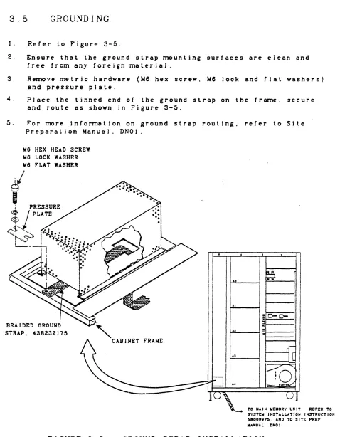
3.5
GROUNDING
1. Refer to Figure 3-5.
2. Ensure that the ground strap mounting surfaces are clean and
free from any foreign material.
3. Re~ve metric hardware (M6 hex screw, M6 lock and rlat washers) and pressure plate.
4. Place the tinned end of the ground strap on the fr~. seeure
and route as shown in Figure 3-5.
5. For rrwre information on ground strap routing. refer to Site
Prepara lion Manua 1. DNO 1 .
M6 HEX HEAD SCREW M6 LOCK WASHER
Me FLAT WASHER
STRAP. 438232175
"
o
CABINET f'RAME~~
:~
,Ri
I
liO-C-
I
H
'
~
I
II"
I
I
10,1
• II
~~~
______
~==~' _tL°cot~
ITO WAIN WEMORY UNIT RErER TO SYSTEW INSTALLATION INSTRUCTION. 58008875. AND TO SITt PREP MANUAL DNOI
FIGURE 3-5.
GROUND STRAP INSTALLATION
58009917
3-6
[image:26.612.73.551.90.704.2]REV C
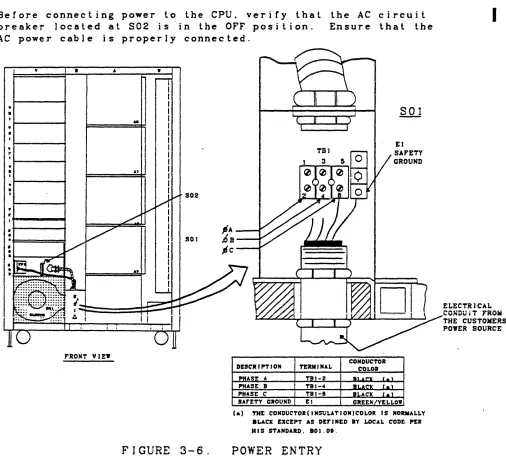
3.6
POWER ENTRY
ENSURE THAT THE CIRCUIT BREAKER AT S02
IS IN THE OFF POSITION BEFORE MAKING THE
POWER CONNECTIONS AT SOl.
The customer's electrician wil1 connect the power cable from the custo~r's power distribution panel to SOI-TBl. See Figure 3-6. The neutral (whi te) lead shall not be brought into the cabinet.
Before connecting power to the CPU, verify that the AC circuit breaker located at S02 is in the OFF position. Ensure that the AC power cable is properly connected.
.,
.,
•
·
.,
• I
I: I
I
.,
•
I.,
• I
.+---+
•
.f=====1•
•
.t----...,...c:~•
FRONT VIEW
58009917 A
..
II at•
rr
II I I I I I II I I I I I I
I
FIGURE 3-6.
CONDUCTOR
DESCRIPTION TERMINAL COLOR
PHASE A TBI-2 JiU~ I . \
PHASE 8 TBI-oC au.cx l . \
PHASE C TBJ-I BLACK ( .
,
SArETY GROUND El GREEJli/YELLOW
(a) THE CONDUCTOR(INSULATION)COLOR IS NORMALLY
.LACE EXCEPT AS DEFINED BY LOCAL CODE PER HIS STANDARD. 80J.08.
POWER ENTRY
HONEYWELL CONFIDENTIAL
&
PROPRIETARY
I
ELECTRiCAL CONDuiT ,ROii THE CUSTOlilERS POYER SOURCE
[image:27.612.75.581.286.742.2]A ISSUED
4.0
4 . 1
APPLYING POWER TO THE CPU
OBSERVE ALL CAUTIONS AND WARNINGS
AS HAZARDOUS VOLTAGE MAY BE PRESENT.
PRE-POWER UP INSPECTION
Perform the following inspection steps:
NOTE
Depressing the CABINET SHUTDOWN switch on the Operator Control Panel bypasses the Power Control Module and the Operator Control Panel POWER OFF
switches. Before power can be appiied the CABINET
SHUTDOWN switch must be in the out position.
1. Ensure that the operations area is clean.
2. Ensure thal the CPU is clean and free of foreign matter.
3. Ens u r e t hat the coo lin g s y stem air f i I t e r s are c I e an.
4. Ensure that the plenum, blower housing and air intake
lou v e r s are c I e a nan d
r
r e e from any 0 b st· rue t jon s .5. Ensure that the CABINET SHUTDOWN switch, located on the
Operator Control Panel is in the out posi lion. See
Figure 4-1.
6. Ensure that al] power conneclions are clean and secure.
7. Ve r i r y t hal a 1] c i r·c u i t boa r d s are pro per J y I 0 cat e dan d sea ted.
OVERTEWP TROUBLE READY NORWAL TEST AC PRESENT
58009917
0 0 0
o
o
o
o
0
ALARM CABINET SHUTDOWN
DOD
CABINET SHUTDOWN SWITCH
FIGURE 4-1. OPERATOR CONTROL PANEL
(CABINET SHUTDOWN SWITCH)
[image:28.612.71.508.86.713.2]4.2
APPLYING AC POWER
Before applying power co~]ele lhe following steps:
I-CADT
I ON
I
THE BLOWER IN THIS UNIT MUST BE
WIRED FOR EITHER 50 HZ OR 60 HZ.
SEE INSTRUCTION LABEL IN BLOWER
COMPARTMENT AT REAR OF CABINET.
REV B
1. Verify that the circuit breaker located at S02 is in the OFF position. See Figure 4-2.
FIGURE 4-2. PRIMARY POWER INPUT CIRCUIT
BREAKER AT S02 (OFF POSITION)
2. Verify that the circuit break~rs located at 803. labeJed FANS and REGULATORS. are in the OrF position. See Figure 4-3.
58009917
lAMP
"2
0
250VOLT SLO BLO0
FI@@@
@@@
n:n:n:n
I
Q
~J:I
I
ON4..J=l.I=U.-l 4.J=U=U-.J
orr
rANS RECULATORS
FIGURE 4-3. FANS AND DC REGULATORS CIRCUIT
BREAKERS AT S03 (OFF POSITION)
.
[image:29.612.64.539.26.785.2]A ISSUED
3. Verify that the Power Control Nodule (located at Vel)
POWER CONTROL-REMOTE/LOCAL switch is in the LOCAL position and depress the POWER CONTROL-OFF swilch. Aiso ensure that the MARGINS-REMOTE/LOCAL switch is
in the REMOTE position. See Figure 4-4.
(@
lie co.,.
eOOLINC
( @
@
@
ID
K 011
[
__
~II-J
I
POWER
eONTltOl.-REMOTE/LOCAL SWITCH
MAK U"-IlEIIOTE/
t.OC AL sw I TCH Ott SHVTDOn acC'" CP I/O ~ta CON TaG I.-orr PITCH
58009917
IIAItCINS
TE .6Y HI
1
@
LOFIGURE 4-4. POWER CONTROL MODULE AT VCl
(MARGINS AND POWER CONTROL SWITCHES)
After these settings are verified. power may be applied in the fo] lowing manner:
1. Ensure lhat the applicable circuil breaker on the site power distribution panel is in lhe ON position.
2. Verify with the electrician lhat the input power to the
CPU is 60 Hz. 3 Phase 208 vac phase to phase. Jf the
power source is 50 Hz. set the customer's circuit breaker to OrF and connect the cooling fans for 50 Hz operation
before proceeding. {Connection inslruclions are located
on the 501 housing.
3. 5 e 1 the c u s lome r 's a p p J j cab J e c i r cui t b rea k e r toO F Fan d
replace the 501 junction box cover.
4. Resel lhe cuslomer's circuit breaker lo the ON position.
5. Set the CPU cabinet circuit breaker located at S02 to ON. (Figure 4-5)
I
I
FIGURE 4-5. PRIMARY POWER INPUT CIRCUIT
BREAKER AT S02 (ON POSITION)
[image:30.612.101.564.86.742.2]1
A ISSUED
6. Verify that the AC ON indicator located on the Power
C.ontrol Module at Vel is illuminated. See Figure 4-6.
At 011
[
__
"
~
IJlDltATGa
@
@)
(
DC COM,. DC ON
0)1 ALAb SHUTDOWN
REC " ' Cit 1/0
."KIIIS
i(rr
E0
usnI
PO"!:. eO"TRO!.
I
REMOTt ON orr
o
©
@
@
bOCA!.
FIGURE 4-6.
1.0
POWER CONTROL MODULE AT VCI
(AC ON INDICATOR)
7. Verify that th€ AC PRESENT indicator and the POWER OFF
indicator located on the Operator Control Panel are
illuminated. See Figure 4-7.
OVERTEIIIP TROUB!.E READY
0. f \ r..
\../ V V
FIGURE 4-7.
NORIllAL TEST
r.. 1'""\
0
V V
e AS i NET SHUTDOWN
0
orrAe PRESENT INDICATOR
POWER orr INDICATOR
0
POWER
Al.ARM
ON REStT
DO
0
OPERATOR CONTROL PANEL (AC PRESENT
AND POWER OFr INDICATORS)
58009917
4-4
[image:31.612.105.512.117.732.2]403
APPLYING DC POWER
ICAUTIONI
DO NOT REMOVE OR INSERT LOGIC BOARDS
AFTER DC POWER HAS BEEN APPLIED.
Apply DC power to the equip~nt in the following manner:
REV C
1. Verify that the OFF/REMOTE switch. located on the +5V Masler Regulator is in lhe REMOTE posilion. See Figure 4-8.
I""'oJ
~
-0
-0
~~
~o~
l'"l<
~:
>
~ Cf:ll.. l'"l
(,0 (,0
"4
or
"'C..,:--
SYITCH orr/REIIOTE-
°
..,
(+5 REe POYER)>O@
Cf -
e
..
"
>
<~
f-O ..c@o
c:~@;
"4
...
-( , 0 1
l ' " l
-z _
fit +
[image:32.612.59.522.78.545.2]l'"l_
..,
... :II l'"l &: 0 "4'"
- t
o
o
IFIGURE 4-8.
+5V MASTER REGULATOR AT VJl
(OFF/RE¥OTE SWITCH)
2. Set the regulators and fans circuit breakers located at S03 to the ON position. See Figure 4-9.
lAMP
F2
0
2S0VOLT SLO BLO0
FI@~@
@@@
rmJrm
~
OFF FANS RECULATORS
@@@
@@@
FIGURE 4-9.
FANS AND DC REGULATORS CIRCUIT
BREAKERS AT S03 (ON POSITION)
58009917
HONEYWELL CONFIDENTIAL
&
PROPRIETARY
I
3.
REV C
Depress the POWER CONTROL-ON switch.
on the Power Contro! Module at VCl.
This switch is located See Figure 4-10.
( . . . . ,..11 \
(@ @)
. . C*IF . . . .
l
J
( §
If
@@@@§§§@
@ )..
"
...
~ _ . . . CPI, •
~===::I::::t::========::::c:::r::===:::I:/=::t::::::!:;.::,~L-*_...
I PWD ~10"
0 Ii
@
I@nl
... &.K'AL
FIGURE 4-10. POWER CONTROL MODULE AT Vel
(POWER-ON SWITCH)
4. If the trouble indicator located on the Operator Control Panel illmninates. press the Ini-Clear pushbutton switch
located on the Configuration Panel to clear. See Figures 4-11 and 4-12.
r---
~ ________ - -__ - -______ - - - -______ ~11~~I~[!Jw!©l
t
INITILIZE-CLEAR SWITCHFIGURE 4-11. CONFIGURATION PANEL
5. Verify that the POWER ON indicalor is il]wninal~d and the POWER OFF indicator is extinguished. These indicators are
located on the Operator Control Panel. See Figure 4-11.
JI'WK. orr IDIC""'"
o
1
~. C ••• UT SIII1T1MMnI AUJIII
D
Dou
T- - - '
FIGURE 4-12. OPERATOR CONTROL PANEL
(POWER OFF AND POWER ON INDICATORS)
6. Verify that the Cabinet Cooling System is operating properly.
58009917
[image:33.612.110.560.43.792.2] [image:33.612.141.519.78.261.2]REV C
7. Verify that DC ON and DC CONF (confidence) indicalors are
il)wninale~: These indicators are localed on lhe Power
Conlrol Module at VCl. See Figure 4-13.
B.
Verify that the followingLED
alann indicators. located onthe Power Control Module at VCI (Figure 4-13). are nol
illwninated.
a
•
COOLING ALARM
OVER TEMP SHUTDOWN•
O.T. REG (over le~eratuTe regulator)COOLn.c
SHUTDOWN INDICATOR
DC CONF
ALARIII --+----~
INDICATOR
ON AI..UU'
I :
..
K I ••I
!
ii:0,!,£ ",nI
~
LOCAL0
SHUTDOWN
IN.
!
LO
DC ON O.T. aEe
- J
He . . . C'P I/O
PowER C'ONT1tOL
or,.
I
IKESEl' .EIiOTE ON I
@
jL~@
I
~
FOnReONTltOL-aEMOTE/LOC'AL SWITCH
FIGURE 4-13.
POWER CONTROL MODULE AT Vel
(DC CONF. DC ON AND TEMP INDICATORS)
9. Verify that the voltage and overcurrenl adjustments on the
Tegu18tor~ aTe as specified in the Power and Cooling Manuai.
(To Be Supplied).
HONEYWELL CONFIDENTIAL
&
PROPRIETARY
4-7
I
[image:34.612.67.548.82.653.2]A ISSUED
4.4
POWER SHUTDOWN
4.4.1
NORMAL SHUTDOWN
NOTE
The POWER, CONTROL-REMOTE/LOCAL switch
located at VCl (see Figure 4-12) must
be in the REMOTE position when removing power via the Operator Control Panel.
I. Depress and release the POWER-OPF switch located on the Operator
Control Panel. See Figure 4-14.
OVERTEWP TROUBLE READY NORIIAL TEST AC' PRESENT
0
0
0
0
0
0
0
0
POWER
CABINET SHUTDOWN "URM
orr ON RESET
D
0 00
POYER orF SYITCH
FIGURE 4-14. OPERATOR CONTROL PANEL
(POWER
OFF SWITCH)
2. Sel the CPU PRIMARY POWER INPUT circuit breaker at S02 to OFF. See
Figure 4-15.
[image:35.612.65.555.61.706.2]OFF ON
FIGURE
4-15.
PRIMARY POWER INPUT CIRCUIT BREAKER
AT S02
(OFF
POSITION)
3. Sel the equipmenl circuil breaker at the site main power dislribution
panel to the OFF position.
58009917
4-8
REV C
4.4.2 EMERGENCY SHUTDOWN
Should an e~rgency shutdown beco~ necessary due to a hazardous
condition. equip~nt malfunction. or otherwise. the following
steps are to be followed:
1. Press the CABINET SHUTDOWN switch located on the Operator Control
Panel. See Figure 4-16.
OVERTElIP TROUBLE READY
0
0
0
FIGURE 4-16.
)fORMAL TEST AC PRESE)fT
0
0
0
0
0
POWER CABINET SHUTDOWN OFr ON
0
It00
CABJHET SHUTDOWN SWITCH
OPERATOR CONTROL PANEL
(CABINET SHUTDOWN SWITCH)
ALARM RESET
0
2. Set the equipment circuit breaker at the .site main power distri-bution panel to the OFF position.
4.5
NOTE
Depressing the CABINET SHUTDOWN switch on the Operator Control Panel bypasses the Power Control Module and the Operator
Control Panel POWER OFF switches. Before
power can be applied the CABINET SHUTDOWN switch must be in the out position.
POWER SYSTEM CHECKOUT
The position of the POWER CONTROL-REMOTE/LOCAL switch on the Power Control Module (VC1) detennines whether DC power will be controlled
locally (i .e .. at the Power Control Module) or remotely {i .e .. at
the Operator Control Panel}. During the checkout procedure. it will
be asswned that the POWER CONTROL-REMOTE/LOCAL switch is set to REMOTE.
See Figure 4-18.
I
58009917
4-9
REV C
Depress the POWER ON switch located on the Operator Contro! Panel. See Figure 4-17. Verify that the following events occur:
•
The POWER ON indicator is illwninaled. located on the Operator Control Panel.This indicator is See Figure 4-17.
• The POWER OFF indicator is extinguished. This indicator is located on the Operator Control Panel. See Figure 4-17.
POWER ON I ND I CA TOR
PCnreR
0,.,.
INDICATOR aVERTEMP TROUBLE READY NODAL TEST AC PRESENT0 0 0
o
o
o
PO'ER
o
ALAiUI
DOD
CAB I NET SHUTDOWN
PO'ER ON SWITCH
I
•
FIGURE 4-17.
OPERATOR CONTROL PANEL
(POWER OFF AND POWER ON INDICATORS)
The DC ON and DC CONF indicators are illuminated. The indi-cators are located on the Power Control Module (VCl). (See
Figure 4-18.)
Regulated DC power is now being applied to the logic circuits.
AC COOL 11M:
( @
@
ON
LOCAL
FIGURE 4-18.
De CORr INDICATOR
@
@@@@§SiJi@
@ )
OYER TEMP
Be Pn CP 1/0
Hsn
I
POYER CONTROL
I
UiY)
@ @
©
LO LOCAL
POYER
CONTROl--REMOTE/LOCAL SWITCH
POWER CONTROL MODULE AT VCl
(DC INDICATORS AND SWITCHES)
5800991r
HONEYWELL CONFIDENTIAL
&
PROPRIETARY
I
[image:37.612.70.577.119.718.2] [image:37.612.100.514.442.720.2]REV C
Should the DC CONF indicator remain erf and/oT if a power regulator
REG
FAULT light is illuminated. resequence the power-up procedure(paragraph 4.3). Replace any power regulator/fuse whose REG FAULT
indicator remains illuminated. The fuses (IA. 250V SLO 8LO) labeled
Fl and F2 located at S03 protect the voltage control circuit. A
[image:38.612.66.526.196.730.2]blown fuse will prevent power from being applied. See Figure 4-19.
FIGURE
4-19.
F20
lAMP 250 VOl.T SLO BLO FUSES
F1
@@@
@@@
cmrmON
orrFANS RECULATORS
@@@ @@@
FANS
AND DC
REGULATORS
CIRCUIT
BREAKERS AT S03
(SLO
BLO
FUSES)
4.6 OFFLINE r&D'S
Run PAS (Processor And Siore) test in Multics mode.
4.7
ONL I NE r&D'S .
Bring system up with Mullics.
I
I
58009917
4-11FA ISSUED
5.0
DEINSTALLATION
This section provides procedures for the physical removal of the CPU
from the c u s tome r . sop era t ion a 1 sit e . J n s p e c t ion. i n v en tor y. dis
-assembly/handling. packing/crating and shipping procedures are also included in this section.
5 . 1
SITE INSPECTION
Deinstallation. preshipment and site readiness inspection reports shall be made according to the Field Engineering Procedures Manual. These procedures include:
1. Consulting with the customer before and after site ins~ection.
to determine the customer's deinstal lalion requirements.
2. Obtaining required shipping documents such as the Bill of Lading and the Memorandum of Shipment.
3. Obtaining the unit's FCO (Field Change Order) log book and uninstal1ed FCO·s.
4. 0 j s c u ssw i t h 1 h e c u s t orne r sui t:a b l e t j min g for r erno va) C? f 1 he
e q u j pme n t t hat w j 1 1 res u 1 t i n min i mwn imp act 0 n sit e 0 per a t ion s .
5. Note any possible impediments which may hinder the safe removal
o f t h ':! e qui pme n t s u c has door way s. h a I J s. s t e p s / r amp s. etc. A Iso
report on packing. crating and Joadin& facilities and if any special packing and handling will be required.
5.2
EQUIPMENT INVENTORY
Complete equipment inventory provides verification that the CPU and
its associated )og~. uninstalled FCO's and options are present before
packing and packaging are initiated.
A careful physical inventory should be made by verifying that equip-ment serial numbers correspond to inventory serial nwnbers. where provided. and that any discrepancies are reported immediately to the District Office via the established channels.
58009917
HONEYWELL CONFIDENTIAL
& PROPRIETARY
A ISSUED
5.3 DEiNSTALLATION PROCEDURE
The following procedure is given as a guide to the Field Engineering Representative to deinstal) lhe CPU.
REMOVE ALL POWER TO THE EQUIPMENT
PRIOR TO DEINSTALLATION.
OBSERVE
ALL WARNING AND CAUTION LABELS ON
THE EQUIPMENT.
DANGEROUS VOLTAGES
MAY BE PRESENT IF THE CAPACITOR
OPTION. WCAP68LA IS INSTALLED.
1. Perform a norma) unit turn orf procedure.
2.
3.
4.
5.
6.
7.
8.
9.
Turn off unit main power circuit breaker at S02.
Turn off site power to the unit and disconnect the power cable from site power.
The custo~r's electrician should remove the cover at SOl
and disconnect the custo~r's power cable.
R erno v e. i n v e n tor y an d pac k age the 0 p t ion s .
Disconnect and secure the harnesses to the cabinet fr&ne.
Disconnect. ciJ and lag cables.
Inventory the logic boards and ensure that they are properly connected to the backpanel connectors.
Remove the frmne ground cables (see Figure 3-5).
10. Remove the lower front and rear trim strips.
11. Raise the four JeveJ ing pads on the cabinet so that the cabinet
is supported on the casters {see Figure 3-1}.
12. Carefully move the equipment to the customer's designated packing
and shipping area.
58009917
A ISSUED
5.4
HANDLING AND SHIPPING
During the handling and shipping procedure. perform a final
inventory. Shipping docwments should be prepared and
transpor-t ali 0 n co n
r
i TIne d ;5
.4. 1PACKING AND INVENTORY
Jnspect and inventory the cabinet and contents. Ensure that the
disconnected harnesses have been taped. tagged and secured to lhe frame.
Disconnected cables are to be packaged.
To ensure proper packing. refer 10 lhe shipping specification.
58067223 and/or conlact lhe Honeywel J Packaging Engineer al:
5.4.2
H 0 n e y we] l I n forma t ion S y stems
P. O. Box 6000
Phoenix. Arizona 85005
Mail Stalion C38
CRATING AND SHIPPiNG
Inspect the packing before closing the cabinet doors.
To ensure proper crating. refer to the shipping specification.
58067223 and/or contact the HoneyweJ J Packaging Engineer at:
H 0 n e y '\IV ell 1 n
r
0 rma t jon S y stemsP. o. Box 6000
Phoenix. Arizona 85005
Mail Station C38
Return equipment to:
H 0 n e y we] l I n forma t ion S y stems
LJSD
4001 West Indian School Road
Phoenix. Arizona 85019
LiSi) Warehouse
Mail Stalion J2
5.4.3
SPECIAL INSTRUCTIONS
Inform the carrier or any special instructions. Obtain and
retain the signed equipment receipt.