Applied Mechanics and Materials Vols. 465-466 (2011 pp 1370-1374 A (2014) Trans Tech Publications, Switzerland
doi: I 0. 4028/www. scientific. net/AMM. 465-466. I 3 7 0
Effect
of
GMAW-CMT Heat
Input
on
Weld
Bead
Profile
Geometry
for
Freeform Fabrication of
Aluminium
Parts
Abdullah
Wagiman
t'",
Md Saidin Wahab
1'b,Zazuli Mohidl'",
Azuddin
Mamat2'd
rAdvanced Manufacturing and MaterialCentre (AMMC), UniversitiTun Hussein Onn Malaysia, Johor, Malaysia
2Faculg
of Engineering, Universiti Malaya, Malaysia
"abdulla@uthm.edu.my, bsaidin@uthm.edu.my, ?azuli@uthm.edu.my, dazuddin@um.edu.my
Keyrrordr:
Froeform Fabrication, Gas Metal Arc Welding - Cold MetalTransfer (GMAW-CMT).Abstract. In developing a new method for weld based freeform fabrication, parameter affecting the
geometry
of
single-pass need to be determined asit
has great influence on dimensional accuracyand mechanical property
of
metallic part.In
this paper, profile geometry and microstructureof
single pass weld bead developed using Gas Metal Arc Welding-
Cold Metal Transfer(GMAW-CMT)
was investigated. Observationon
cross sectional weld bead indicates GMAW-CMT hascapability to produce free spatter and crack defect weld bead. Profile geometry measurement shows
weld bead develop at higher heat input has
width
size larger than the weld bead develop at lower heat input. Microstructure examinationin
the substrate reveals formationof
columnar dendritic, cellular and planar structure while at buildup layer exhibit equiaxed dendritic structureIntroduction
Knowing and understanding customers' needs and want is a key for success in business. Each
business player need to meet timely the customers' need and want in order to survive. The changes
of need and want
of
the customer inculcate the business players more focusing on faster product development and reducetime
to
reachthe
market. However, new product development phaseinvolve creating tool and prototype which represents one of the most time consuming and costly.
Therefore, this situation gives a problem to the
firm
if
the order is low-volume products or rapidlychanging high-volume products
In order to overcome the problem, a technology called Rapid Protogping (RP) is introduced in industry. This technology also known as freeform fabrication has been invented since 1990's. [1]. Its originally use for fabrication of prototype models. This technology gives benefits to the user in
term
of
lesstime
and costin
new product development phase. These benefits have atkacted researchers to apply RP in producing a functional productin
several applications. This including applicationin
producing patternfor
castings[2],
denture[3],
scaffold[4],
medical devices andpharmaceutical [5], wood furniture [6] and metallic
partUl.
In the last few years, many researchers have undertaken studies to produce functional component
of
metallic part using weld deposition based due to higher deposition rate, lower cost and safer.Various arc welding such gas tungsten arc welding (GTAW) [8], gas metal arc welding (GMAW)
[9] and submerge arc welding (SAW) [10] have been investigated. However, these processes have a
drawback on controlling the spaffer and distortion. Other work
in
this area was also look on theapplication of non-arc deposition process such as laser [11] and electron beam welding [12]. The
result shows the process capable to produce non-spatter product with less distortion due to localized heating of high energy density. However, these processes incur high initial cost
if
compared witharc welding.
A new modified GMAW, identified as Gas Metal Arc Welding
-
Cold Metal Transfer (GMAW-CMT) offer low initial cost, controllable spatter and low heat input [13]. GMAW-CMT integratesthe wire motions with metal transfer condition via a digital process control. This integration enables
the
system detectingthe
shortcircuit. Every time
the
shortcircuit
occurs,the
systemwill
mechanically control the wire retraction to help detach the molten droplet, thus greatly decreasing the heat input and spatter during welding. With the advantages previously described, GMAW-CMTmeets the requirement
of
freeform fabricationto
develop quality metal parts. During the forming process, geometryof
single-passweld
bead has great influenceon
dimensional accuracy andmechanical property of metallic part. Therefore, this research work aim to determine the effect
of
heat input on the weld bead profile geometry.
Experimental Equipment and Procedure
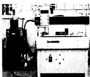
The experiment was carried out using GMAW-CMT welding source with an expert system made
by EWM GmbH as shown in Fig. 1. Consumable material used was
Alsis
I
mm in diameterfiller
wire and argon gas at a flow rateof
15 L/min as the shielding gas. The weld torch was fixed to the 3axis CNC table to provide a constant welding speed and arc length during the deposition process.
The angle of CMT arc torch was set at 60o with respective to the workpieces.
Al606l-T6
plate isplaced on an
x-y
axis table and used as the substrateto
build up the weld bead. Priorto
theexperiment, the surface
of
the samples waswire
brushed atrd cleanedby
acetoneto
eliminate aluminium oxide on the surface. Several single-pass layers are produced with different heat input inthe experiments to decide their effects on the weld geometry. Table
I
shows welding parametersof
different heat inputs. These are the rangesin
which the deposition was stable. The heat input is calculated using Eq.1.Fig. 1 GMAW-CMT welding machine
Q =
60:il-x!
(1)(S
x
1000)Where Q is welding heat input in kJ/mm,
V
is the mean welding voltage in volts,I
is the meanwelding eunent in ampere and S is the welding speed in mm/min.
Single pass weld bead were build up on 27 specimens.
All
specimens werefirst
inspected by liquid die penetration to obtain non-crack weld bead. Then the weld beads were cut cross-sectionedinto small specimen using
a
diamond cut-off wheel and mountedin
epoxyfor
bead dimension measurement and metallographic analysis.The
bead dimensionwas
measured using profile projector. Meanwhile, specimens for microskucture examination undergoes grinding and polishing before etchwith
keller
reagent.The
microstructure examination was examined using optical [image:2.593.218.372.351.483.2]1372
4th Mechanical and Manufacturing Engineering
Table
w
Specimen Voltage, (V) Current (Amp) Weldine Soeed (mm/min) Heat Input (kJimn)
l8 00 400 0.270
2 l8 05 500 0.227
J l8 10 600 0.198
4 l8 00 500 0.219
5 l8 00 600 0,180
6 l8 05 400 0.284
1 t8 l0 400 0.297
I
l8 05 600 0.1899 l8 l0 500 0.238
0 19 05 500 0.239
t9 00 400 0.285
2 t9 t0 600 0.209
l9 00 500 0.228
4 t9 00 600 0.190
5 l9 105 400 0.299
6 19 05 600 0.200
l9 l0 500 0.251
I
l9 10 400 0.3149 20. l0 600 0.221
20 20. 105 500 0.253
71 20. 100 400 0.302
22 20. lt0 500 0.265
23 20. 110 400 0.332
24 20 105 600 0-21I
25 20. 105 400 0.3r7
26 20. 100 500 o.241
27 20. 100 600 0.20I
Result and Discussion
Weld Bead
Profile
Geometry. Fig.2
shows an image observed by profile projector on selected cross section of single pass weld bead. The single pass weld bead present half-ellipse shape and freespatter defect.
Fig.2 Cross sectioned weld bead
Fig.3 (a-b) shows the effect
of
heat input on the weld bead profile geometry. The weld beadwidth increases with an increase of heat input.
A
model fitted using linear regression on the data(Fig. 3 (a)) produced
Y:
21.98X+
1.31with
coefficient determination,Rl of
0.8. TheR'value
near
to
1 shows the weld bead width is highly dependentwith
the heat input. Similar trend wasfound to the height of the weld bead as shown in Fig. 3 (b). The height of the weld bead increases
with an increase of heat input. The data produce linear regression model of
Y:2.76X +
1.24 and has R2 of 0.53. The R2 value of 0.53 indicates that abaut 53o/o of the variation in weld bead height can be explained by the relationship to the heat input. The result shows that the weld bead developed athigher heat input has width size larger than the weld bead developed at lower heat input. This could
be explained by the effect of welding current, arc voltage and welding speed on the heat input. The
heat
input
is
directly proportionalto
the
welding current andarc
voltage besides inversely proportional to the welding speed. Increasing the welding current and arc voltagewill
increase theheat input, so that more heat were supply to the
AlSi)
and resultin
more metal deposited on the substrate. However the situationis
reversedif
increasing the welding speed. The heat input is decreaseswith
an increasein
the welding speed; thus, resultsin
lessAlSi5
deposited on thealuminium substrate and cause the weld bead width size decrease. However, effect of gravity and
solidification rate giving constrains to weld bead to increase on height.
y =2.76x+ !.24 R'= 0.53
e2
bo
{)
1
9
^t
Tt
$e
F5
4
0.2
0.25
0.3
0.35Heat input (kJ/mm)
(a)
0.2
0.25
0.3
0.3sHeat input (kJ/mm)
(b)
Fig, 3 Effect of heat input on weld bead profile (a) Effect on width (b) Effect on height
;,..
PM^Z(a)
-'r)'n
.,,L,4Ti
.A
-
^\*
(c)
(b)
(d)
Fig.4 Microstructure images of various location on deposited layer and substrate obtained using
OPM (a) FZ at Buil-up layer X50 (b) interface of FZ andPMZ at substrate
(c)HAZ
at substrate1374
4th Mechanical and Manufacturing Engineering
Microstructure
examination. The microstructuresof
the deposited AlSis are dependent on thelocation. Each location has different heating and cooling rate during the process. Rapid cooling
yield finer grain while slow cooling result
in
coarse grain. Fig. 4 shows the microstructure in the deposited layer, interface between firsion zone (FZ) and partially melted zone (PMZ), heat affectedzone (HAZ) and substrate base material which unaffected. The microstructure at the buildup layer exhibit equiaxed dendritic structure. This structure is formed due to air cooling on fusion of AlSis
filler
material which deposited onthe
substrate. Meanwhile, microskucture examinationin
thesubstrate (penetration location) reveals formation
of
columnar dendritic, cellular and planarstructure.
Conclusion
Observation on cross sectional weld bead indicates GMAW-CMT has capabilify to produce free spatter defect AlSis weld bead that build-up
an
A1606lT6 substrate. Heat input of GMAW-CMT isstrongly affect the profile geometry of weld bead width. The width size increases significantly with an increase in the heat input. The effect of heat input on width size is more pronounced than the
height. Investigation
on the
microstructuresof
the
depositedAlSi5
revealsthe
structure isdependent on the location. Each location has different heating temperature and cooling rate during
the process. Rapid cooling yield finer grain while slow cooling result in coarse grain. References
tl]
E.
Sachs,M.
Cima, and J. Cornie, Three-dimensional printing: rapid tooling and prototypesdirectly from a CAD model, CIRP Annals - Manufacturing Technology 39 (1990) 201--204.
t2]
X.
Li,L.
Zhang, and X. Yin, Microstructure and mechanical properties of three porous Si3N4ceramics fabricated by different techniques, Materials Science and Engineering
A
549 (2012) 43-49t3]
Y. Sun, P. Lii, and Y. Wang, Study on CAD&
RP for removable complete denture, ComputerMethods and Programs in Biomedicine 93 (2009) 266-272
M.
Lee, J.C.Y. Dunn, andB.M. Wu,
Scaffold fabricationby
indirect three-dimensionalprinting, Biomaterials 26 (2005) 4281-4289,.
D.-G.
Yu,
C. Branford-White, Z.-H.Mq
L.-M.
Zhu,X.-Y.
Li,
andX.-L.
Y*9,
Novel drugdelivery devices for providing linear release profiles fabricated by 3DP, International Journal
of
Pharmaceutics 370 (2009) 160-166t6l
M
Saidin Wahab,Abdullah
Wagiman, Mustaffalbrahim,
Developmentof
wood-based composites material for 3d printing process, Applied Mechanics and Materials 315 (2013)987-99r
t7]
G. Sansoni and F. Docchio, Three-dimensional optical measurements and reverse engineeringfor automotive applications, Robotics and Computer-Integrated ManufacturngZA Q004)
359-367.
tSl
-
-
Huijun Wang, Wenhui Jiang, Jiahu Ouyang, Radovan Kovacevic, Rapid prototypingof
4043 Al-a1loy partJby VP-GTAW Journal of Materials Processing Technology 148 (2004) 93-102[9]
Yong Ca-o n, ShengZhu,Xiubingliang,WanglongWang, Overlapping model of beads and curve-
-
fitting of bead section for rapid manufacturing by robotic MAG welding process, Robotics and
Computer-Integrated Manufacturing 27 (20 1 1 ) 64 1445
-t10]K. Kissmaul, F.W. Schoch, H. Lucknow, High quality large components "shape welded" by a
SAW process, Welding Journal 62 (9) (1983)
17-24-[ll]Jae-Ho
Lee,
Jeong-Hwan Jang, Byeong-DonJoo,
Hong-SupYim,
Young-Hoon Moon, Application of direct laser metal tooling forAISI
H13 tool steel, Trans. Nonferrous Met. Soc.China 19 (2009) 284-287
ll2]P.
Wanjara,M.
Brochu,M.
Jahazi, Electron beam freeformingof
stainless steel using solid wire feed, Materials and Design 28 (2007) 2278-2286tl3lH.T.
Zhang, J.C. Feng, P. He,B.B.
Zhang, J.M. Chen,L.
Wang, The arc characteristics andmetal transfer behaviour of cold metal transfer and its use in joining aluminium to zinc-coated
steel, Materials Science and Engineering