Cite this article as:
O’Kelly B.C., Hodgetts S.J. and Leung T.H.F. 2006. Stabilisation of Stanton Lees
landslip using pile retaining wall solution.
Third Symposium on Bridge and
Abstract
A landslip in the village of Stanton Lees, Derbyshire, UK, was reported in November 2000 following a period of torrential rainfall. The slip resulted in the gradual and progressive down-slope movement of a relatively steeply sloping embankment that had supported an existing gabion retaining wall and a minor road which was subsequently closed to vehicular traffic. This paper describes the site, an interpretation of the ground conditions, onsite monitoring data and the design and construction of the remedial works necessary to return the road to serviceability.
The landslip occurred due to the superficial deposits moving over the weathered bedrock under conditions of elevated groundwater following a period of heavy rainfall. Autumn 2000 was the wettest season since local records began in 1870. A stability analysis indicated that the embankment slope was at limiting equilibrium and was particularly sensitive to relatively minor fluctuations in the groundwater levels. The remedial works involved replacing the existing gabion wall with a cantilevered, 600-mm diameter, bored pile retaining wall that comprised two rows of piles, staggered in plan arrangement, and located along the southern verge of the road.
Keywords: Landslip, stabilisation, retaining wall, pile, rainfall
Stabilisation of Stanton Lees Landslip using Pile
Retaining Wall Solution
Brendan C. O’Kelly,
Lecturer in Civil Engineering, Trinity College Dublin, Ireland
formerly Scott Wilson, UK
Steve J. Hodgetts,
Associate, Scott Wilson, Chesterfield, UK
Terence H.F. Leung,
INTRODUCTION
Background
A landslip in the village of Stanton Lees, Derbyshire, UK, was reported in November 2000 following a period of torrential rainfall. The site is located on the eastern side of Stanton Peak at an elevation of 180–190 mAOD. The landslip resulted in the failure of an embankment, the outward displacement and settlement of an existing gabion retaining wall and damage to a minor road that was subsequently closed to vehicular traffic. Derbyshire County Council engaged Scott Wilson to carry out a geotechnical investigation to determine the cause of the landslip and to design remedial measures to return the road to serviceability. This paper describes the site, an interpretation of the ground conditions, onsite monitoring data and the design and construction of the remedial works.
Site Description
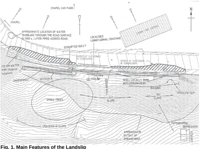
The embankment, constructed between 1955 and 1962, is located in front of Cherry Tree cottage and, in plan, is about 90 m in length (Fig. 1). The hillside is characterised by pronounced undulations extending from the foot of the gritstone crags behind Stanton Lees village (Stanton Moor Edge) to Hillcarr Farm at an elevation of about 120 mAOD. Springs discharge off the hillside to the relatively level ground behind Lees Road to the north of the landslide before percolating underground as groundwater flow.
[image:4.595.71.478.461.762.2]The embankment is straddling a gentle topographic depression centred roughly on a cesspit at the base of the slope, which trends in a northwesterly direction in front of the cottage. To the west of the depression, a benched spur follows the curve of the road into the valley below the chapel. The embankment slope is at a maximum of 35–40 degrees in front of the cottage. The embankment showed signs of bulging and cracking over some of its length with a small slip scar to a shallow slip present in the eastern part of the slip where the slope was at its steepest. Below the embankment the natural hillside is undulating with occasional ridges across the slope.
Landslip
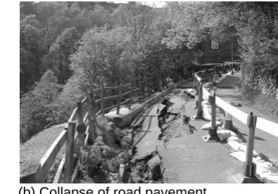
The landslip occurred on the down-slope side of the single-carriageway road located between Cherry Tree cottage and the chapel. The road, which falls in elevation by about 4 m between the chapel and the cottage, had a longstanding problem of instability. The slip was reactivated in November 2002, and over the following period of 14 months, the southern half of the road had settled locally by up to 1.5 m along an affected length of about 60 m and had caused outward destabilising movement of the gabion wall by as much as 1.0 m, Fig. 2.
[image:5.595.329.527.186.324.2](a) Down-slope movement of existing gabion wall (b) Collapse of road pavement
Fig. 2. The Stanton Lees Landslip
The gabion wall, about 45 m in length and 2.5 m in height, had been constructed in stages with the oldest section (adjacent to the chapel) having been built in 1985/1986 and the most recent section (immediately down slope of Cherry Tree cottage) built at least in part, in March 2000. The embankment supporting the gabion wall had slipped by 0.5–1.0 m. The rear of the landslip was defined by the rear scarps seen in the road, the vertical scarp immediately below the wall and by the lateral extent of distress in the road. No distress had been noted in the northern part of the road or to the chapel or Cherry Tree cottage.
SEQUENCE OF EVENTS
The only reasonably comprehensive records available that detailed the development of the
slip were the recollections of the occupier of Cherry Tree cottage. On the 5th November 2000,
a single kerbstone directly outside the cottage was reported to have dropped overnight such that its top was level with the road. The following day the field below the gabion wall was flooded and over a period of about two weeks, cracks began to appear outside the cottage along the southern verge of the road, parallel to the kerb line. After several months of gradual downward movement, the gabions began to move outwards, while after further several months, the gabions outside the cottage began ‘pulling apart’. The area adjacent to the chapel was reported to have begun moving shortly after the area outside the cottage. In March 2002, the water flow from a plastic discharge pipe at the western end of the wall ceased. From the commencement of Scott Wilson’s involvement in the investigation in May 2000, gradual settlement of the ground was recorded, particularly after periods of heavy rainfall.
DESK STUDY
Geological Maps and Memoirs
Rainfall Data
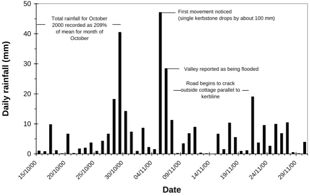
Figure 3 shows daily and monthly rainfall data for the period preceding the landslip to May 2002, obtained from a weather station located at Middleton (National Grid Reference SK25 275557), about 7 km to the south of the slip. The weather station is at an elevation of 321 mAOD, i.e. about 140 m above the Stanton Lees slip. As the weather station is remote from the slip, it is likely that variations in rainfall intensity over short periods would exist between the sites. However, the overall trend of rainfall for both sites might be expected to be broadly similar. 0 10 20 30 40 50 15/1 0/00 20/1 0/00 25/1 0/00 30/1 0/00 04/1 1/00 09/1 1/00 14/1 1/00 19/1 1/00 24/1 1/00 29/1 1/00 Date Daily r ainf all ( mm )
First movement noticed
(single kerbstone drops by about 100 mm) Total rainfall for October
2000 recorded as 209% of mean for month of
October
Valley reported as being flooded
Road begins to crack outside cottage parallel to
kerbline
(a) Daily data (15th October–30th November 2000)
0 50 100 150 200 250 Oct-0 0 Nov -00 Dec -00 Ja n-01 Feb -01 Mar -01 Apr -01 May -01 Ju n-01 Jul-0 1 Aug -01 Sep -01 Oct-0 1 Nov -01 Dec -01 Ja n-02 Feb -02 Mar -02 Apr -02 May -02 Month Mon th ly rainf all ( mm ) 169% 145% 167% 136% 169% 53% 58% 70% 244% 45% 111% 209% 212% 138% 51% 124% 98% 167% 130% 49% Slip reactivated
Outward movement of wall reportedly begins Several months of
steady downward movement
Locally, over 300mm of vertical deformation at wall
[image:6.595.79.397.206.407.2](b) Monthly data (Oct. 2000–May 2002). Note: figures relate to percent typical monthly rainfall
Fig. 3. Rainfall Intensity Recorded at Middleton, Derbyshire, UK
On 5th November 2000, 47 mm of rainfall was recorded at Middleton with a further 28 mm
recorded the following day. Heavy rainfall preceded the 5th November event with October
[image:6.595.79.398.432.631.2]SURVEY DATA
General
The movement of the unstable ground and the groundwater levels were monitored over a
period of 14 months prior to the remedial works. Between 13th September and 23rd November
2001, 25 survey points (comprising Hilti nails driven into the tarmac) were installed along the
road above the gabion wall. On 25th April 2002, four lines of between seven and eight wooden
pegs were driven into the embankment and natural ground below, at right angles to the wall. A further two lines of pegs were installed on either side of the landslip to identify the lateral extent of any movement.
Survey Nails
Figure 4 shows the most substantial movement was recorded in front of Cherry Tree cottage and at points located on the retaining wall, and within the sunken road at the western part of
the slip. Half of the movement took place between 11th January and 5th March 2002, which
coincides with the high total rainfall figures recorded at Middleton (i.e. 200 mm for the month of February alone). The survey points located on the northern side of the road showed no significant signs of either vertical or horizontal movements with any recorded movements well within the survey error of ± 4–5 mm.
[image:7.595.111.353.334.456.2]-450 -400 -350 -300 -250 -200 -150 -100 -50 0 50 1 3 /0 9 /0 1 2 6 /0 9 /0 1 2 6 /1 0 /0 1 1 2 /1 1 /0 1 2 3 /1 1 /0 1 0 6 /1 2 /0 1 2 4 /1 2 /0 1 1 1 /0 1 /0 2 0 5 /0 3 /0 2 0 9 /0 4 /0 2 2 5 /0 4 /0 2 0 9 /0 5 /0 2 1 3 /0 6 /0 2 Time V er tica l mo ve men t ( mm )
Fig. 4. Vertical Movements for Survey Points at Road Level
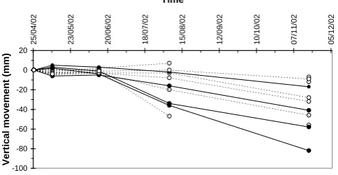
Survey Pegs
Several pegs located on the embankment moved down-slope by up to 80 mm indicating an underlying trend related to a developing landslip. The most significant down-slope movements were recorded at the embankment crest, Fig. 5.
[image:7.595.111.356.591.718.2]-100 -80 -60 -40 -20 0 20 2 5 /0 4 /0 2 2 3 /0 5 /0 2 2 0 /0 6 /0 2 1 8 /0 7 /0 2 1 5 /0 8 /0 2 1 2 /0 9 /0 2 1 0 /1 0 /0 2 0 7 /1 1 /0 2 0 5 /1 2 /0 2 Time V er tica l mo ve men t ( mm )
GROUND INVESTIGATION
In total, 19 boreholes were drilled through the embankment (to depths of up to 13.6 mbgl) and seven trial pits were excavated during in the course of three separate ground investigations conducted at the site in 1999, 2001 and 2002. The drillholes were progressed between testing and sampling locations using a tri-cone rock-roller bit with air flush. The holes were progressed below rock head using rotary coring techniques with a triple-tube core barrel and air flush to produce cores 70-mm in diameter. Core recovery was generally poor throughout indicating either bands of more advanced weathering and/or more intense fracturing. Joints within the sandstone and core recovered adjacent to the inferred zones of no recovery in the mudstone and siltstone were damp and wet, respectively.
Standpipe piezometers fitted with piezometer buckets were installed in all of the boreholes drilled during the 2002 investigation. The buckets comprised a string of plastic tubes, closed at each end but with perforations to allow the inflow of water, and with lead weights on the bottom of the bucket string to maintain their position in the boreholes as the water level increased. The buckets were placed at 0.5-m centres over the anticipated range of groundwater fluctuation. The presence of groundwater was recorded in all of the instruments.
STABILITY BACK ANALYSES
Geological Profile
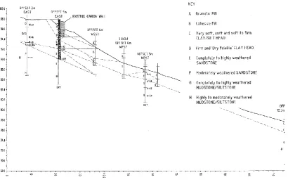
The most adverse ground conditions with respect to slope stability were identified passing through the embankment slope in front of Cherry Tree cottage (Fig. 6). This section had the steepest embankment profile, the greatest thickness of superficial deposits overlying bedrock and the maximum wall deformation, with the slope at the limiting equilibrium condition. Very soft to firm Head and embankment fill materials were present beneath the site. Localised softening occurred due to seepage from the underlying sandstone and mudstone or possibly seepage from redundant water mains beneath the road. Minor shear surfaces of limited persistence were recorded in some of the trial pits immediately below the interface between the Head material and the completely weathered mudstone.
[image:8.595.72.483.482.741.2]Error!
Groundwater Conditions
The highest observed groundwater levels recorded behind and down-slope of the existing gabion wall were used to model the groundwater profile. In addition, a value of the highest observed groundwater levels plus 1.0 m was modelled to simulate the effect of rising groundwater on slope stability. The use of still higher groundwater levels would have required a commensurate increase in the soil strength parameters to achieve limiting equilibrium and as such could have lead to an unsafe remedial design based on strength parameters higher than those that actually existed.
Soil Parameters
Preliminary soil parameters were obtained directly from the ground investigation and
laboratory test results or indirectly using published correlations against insitu and laboratory
test results. The peak and residual values of the effective stress shear strength parameters were determined using consolidated-undrained triaxial compression tests with measurement of pore water pressures, and ring shear tests, respectively. Site observations and the findings of the ground investigation suggested that the landslip occurred due to the superficial deposits moving over the weathered bedrock and as such the weathered bedrock was simply ascribed notional and conservatively high parameter values to ensure that the material remained in place during the stability analysis.
Back Analysis
A stability back-analysis of the embankment slope was carried out using the Slope/W
[image:9.595.109.514.453.618.2]software package. A sensitivity analysis was carried out on the design profile to achieve a factor of safety (FOS) at or very close to one (reflecting its marginal condition) to ensure that the effective stress values, listed in Table 1, were realistic. Safety factors from the Morgernstern-Price analysis were adopted as they provide the most rigorous analysis. In the analyses, the rear scarps day-lighted in the road with the slip surfaces day-lighting in front of the gabion wall.
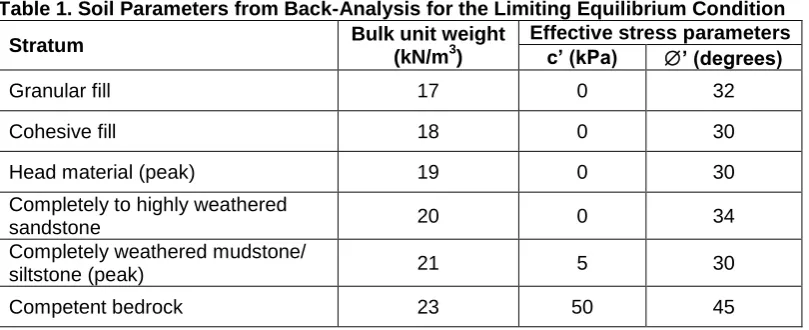
Table 1. Soil Parameters from Back-Analysis for the Limiting Equilibrium Condition
Stratum Bulk unit weight
(kN/m3)
Effective stress parameters c’ (kPa) ’ (degrees)
Granular fill 17 0 32
Cohesive fill 18 0 30
Head material (peak) 19 0 30
Completely to highly weathered
sandstone 20 0 34
Completely weathered mudstone/
siltstone (peak) 21 5 30
Competent bedrock 23 50 45
It was not necessary to invoke the residual shear strength parameter values determined using the ring-shear tests for the Head or completely weathered mudstone materials as the analysis indicated that the embankment slope was at a state of limiting equilibrium adopting the peak parameters listed in Table 1. Furthermore, fully developed residual strength could not have been widespread across the slip; as such a condition would have resulted in catastrophic failure. Consequently, although significant displacement had occurred within the slope, it was considered unlikely that a fully developed slip plane existed at the site. However, it was possible that a more persistent slip plane could develop if the slope were left unremediated.
INFERRED FAILURE MODE
The embankment slope supporting the existing gabion wall probably slipped under conditions of elevated groundwater following heavy and prolonged rainfall. The movement of the slope undermined the wall resulting in its outward and downward movements. The slip surface day lighted immediately beneath or behind the gabion wall, with the subsequent forward movement of the wall resulting in the collapse of the soft and loose backfill behind the wall and the consequent collapse of the road. The forward movement of this fill further contributed to the loading of the head of the slip. It is likely that the forward movement of the wall exaggerated the eccentricity of the loading conditions on the wall resulting in bearing capacity failure.
REMEDIAL WORKS
The remedial works involved replacing the existing gabion wall with a cantilevered bored pile retaining wall. Variations on the retaining wall theme that involved the construction of a retaining wall at mid-height or at the toe of the embankment slope were also considered but practical difficulties in establishing plant on or at the foot of the slope were considered too difficult to overcome. All construction was required to occur from road level to avoid placing plant or temporary works on the slope that could lead to its further destabilisation. An anchored bored pile wall solution was ruled out due to issues surrounding the placement of anchors beneath property adjacent to the site (required anchor lengths of 8–10 m would have reached beneath Cherry Tree cottage and its garden).
The cantilevered bored pile retaining wall solution was analyzed for stability based on a metre
strip of wall using the WALLAP (version 5.01) programme and the Burland-Potts method (net
available passive resistance method). A minimum FOS of 2 was required for the limit
equilibrium analysis. A live surcharge loading of 5 kN/m2 (as specified by Derbyshire County
Council) acted across the roadway. The design groundwater levels were based on the highest observed groundwater levels plus an additional 1.5 m head behind the wall. Friction between the soil and the concrete piles with δ/Ø = 0.66 was considered in deriving the full active and net available passive earth pressures. The failed groundmass on the passive side of the wall was assumed to provide surcharge only to the underlying weathered rock. The worst possible case of slippage was conservatively assumed to be 7.0 m depth to the top of the weathered sandstone. Future down-slope movements of the relatively steeply sloping ground would cause a loss of passive support over this depth. Separate calculations for the design bending moments and shear forces adopted for ultimate limit state of structural members were based
on the full Ko earth pressures.
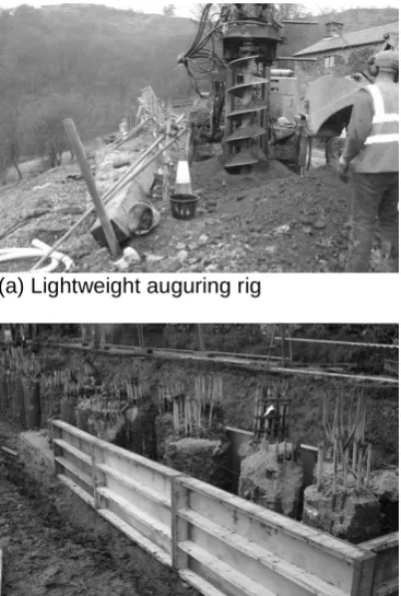
The design required two rows of 600-mm diameter bored piles (86 in total) installed along the southern verge of the road. The locations of the piles were staggered in plan arrangement with a clear spacing of 1.0–1.7 pile diameters between the individual piles (Fig. 7) which had the added benefit of allowing the free passage of groundwater, as compared against a contiguous wall solution. The piles, ranging from 8.0–13.5 m in length, were founded within the underlying mudstone and sandstone bedrock. At these embedment depths, the full active and net available passive earth pressures reach equilibrium so that overturning of the wall was prevented. To allow for the adverse combination of sub-vertical and sub-horizontal fracturing in the bedrock, the embedment depths were increased above the values calculated
(a) Lightweight auguring rig (b) Outermost row of piles
[image:11.595.109.293.75.348.2](c) Placement of formwork for construction of capping beam
Fig. 7. Construction of Bored Pile Retaining Wall
A reinforced-concrete capping beam was constructed to connect the pile heads. A mortared gritstone wall was constructed above the capping beam. Samples of Head and embankment fill materials taken from 2.0–4.0 mbgl were tested to determine aggressiveness to concrete.
Tests yielded results of 7.2–7.3 for pH and 0.19–0.26 %SO4 for sulphate content determined
by 2:1 water/soil extract. In accordance with [3], a soluble sulphate value of 0.26 %SO4 (i.e.
2.6 g/l SO4) required a design sulphate class of DS-3. Assuming mobile groundwater
conditions and for a characteristic pH of 7.2, an ACEC class of AC-3 was specified. Grade 35N concrete was used in the construction of the piles.
The remedial works were carried out onsite by Piling Solutions, UK, using a 25-tonne compact Bauer rig capable of drilling 600-mm diameter holes. Further details on the construction are reported in [4]. Unsuitable subgrade material behind the southern side of the road was replaced with suitable granular fill, which also provided free sub-surface drainage behind the retaining wall.
SUMMARY AND CONCLUSIONS
The reactivation of the landslip in the village of Stanton Lees on the 5th November 2000
resulted in the gradual and progressive down-slope movement of an embankment that supported an existing gabion retaining wall and a minor road. The site was situated on relatively steeply sloping superficial deposits that overlaid undifferentiated mudstone and siltstone of the Millstone Grit Series. Site observations and the findings of the ground investigation indicated that the landslip had occurred due to the superficial deposits moving over the weathered bedrock under conditions of elevated groundwater following a period of torrential rainfall. Autumn 2000 was the wettest season since local records began in 1870.
600-mm diameter bored piles, staggered in plan arrangement, and located along the southern verge of the road. The pile toes were founded within the underlying mudstone and sandstone bedrock and the pile heads were connected using a reinforced-concrete capping beam.
Acknowledgements
Derbyshire County Council Consulting Engineers are kindly acknowledged for granting permission to publish this case study.
References
1. British Geological Survey, Sheet SK26SE, 1:10000 scale (Solid and Drift).
2. Aitkinhead, N., Chisholm, J.I., and Stevenson, I.P., Geology of the country around Buxton, Leek and Bakewell, British Geological Survey, 1985.
3. BRE Special Digest 1: Concrete in aggressive ground. Part 1: Assessing the aggressive chemical environment, Building Research Establishment.
4. Forrest, E., A lasting a cure for the road in ruins, Construction News, 18th September