www.learning-journal.com
JOURNAL
of
LEARNING
Volume 15, Number 12
Using Computer Technology Tools to Improve
the Teaching-Learning Process in Technical and
Vocational Education: Mechanical Engineering
Subject Area
THE INTERNATIONAL JOURNAL OF LEARNING http://www.Learning-Journal.com
First published in 2009 in Melbourne, Australia by Common Ground Publishing Pty Ltd www.CommonGroundPublishing.com.
© 2009 (individual papers), the author(s)
© 2009 (selection and editorial matter) Common Ground
Authors are responsible for the accuracy of citations, quotations, diagrams, tables and maps.
All rights reserved. Apart from fair use for the purposes of study, research, criticism or review as permitted under the Copyright Act (Australia), no part of this work may be reproduced without written permission from the publisher. For permissions and other inquiries, please contact
ISSN: 1447-9494
Publisher Site: http://www.Learning-Journal.com
THE INTERNATIONAL JOURNAL OF LEARNING is a peer refereed journal. Full papers submitted for publication are refereed by Associate Editors through anonymous referee processes.
Mechanical Engineering Subject Area
Salah Mahdi Abdulrasool, University of Huddersfield, West Yorkshire, UK
Rakesh Mishra, University of Huddersfield, West Yorkshire, UK
Abstract: This paper discusses the integration of computer assisted instructions (CAI) with traditional class room teaching. It describes a teaching method to bring real-world of industrial work into the classroom that underscores the need to learn fundamental principles while adding excitement and relevance to the experience. This paper presents results of a case study undertaken to understand the effect of computer assisted teaching methodology on learning effectiveness in classroom en-vironment. The effects of computer assisted instructions on different levels of cognition of individual learners have also been evaluated. The computer aided drawing (CAD), computer aided manufacturing (CAM) and computer numerical control (CNC) courses at the Bahrain institute are an integral part of this attempt. These courses emphasize the development of a 3-D geometric computer model and application of this digital database to all phases of the design process. The students make freehand sketches, build computer models, mate assemblies of parts, perform various analysis, create kinematics simulations, generate final design drawings, import engineering drawing as DXF file, generate NC file to build rapid pro-totypes as shown in the table 1 below.
Keywords: Computer Technology, C.N.C and AutoCad Software
Table 1: Activities and Learning Outcomes
Activities and learning outcomes / Modules Module No
(computer sketching creation of design & drawing). Module 1
Set up the sketch plane units and grid parameters; demonstrate all 2-D sketching primitives; demonstrate all line editing features; make simple extrusions and revolutions to get 3-D geo-metry.Demonstrate the creation and editing of dimensions; set geometric constraints; make simple extrusion and revolution to get 3-D; render the parts.
(computer sketching modelling utilities). Module 2
Create 3-D parts; add feature-based, parametric design features; use advanced sweep operations; edit the geometry in 3-D; render the part.
(computer sketching assembly modelling and mating). Module 3
Create individual 3-D parts; assemble parts as mechanical assembly; mate features as appropriate; check for clearance and interference of parts; create colour rendering of assembly.
computer sketching (engineering drawing). Module 4
Create section views in 3- D and 2-D; create individual 3-D parts; make different 3-D section views of the parts; export acceptable colour image files of 3-D section views for presentation purpose. Project 2-D section views of model; incorporate the 2-D section views into a technical drawing.Generate and dimension three-view drawing on a suitable drawing sheet style; add centrelines where appropriate; dimension the drawing; add a title block and appropriate notes. Save each part as DXF file.
THE INTERNATIONAL JOURNAL OF LEARNING, VOLUME 15, NUMBER 12, 2009 http://www.Learning-Journal.com, ISSN 1447-9494
Rapid prototyping (using data exchange format- DXF and setup check and final manufac-turing).
Module 5
Create cutting parameter for each part (cutting tool, tool size, tool materials, and work materials). Generate tool paths for different layers for each part (X, Y, Z direction, cutting loop, and depth of cut, feed and speed).
Save each part as numerical control (NC) file and send the file to the prototyping machine. Set the work piece; set the tool at zero position; check direction of rotation for the chuck and the cutter; check the work piece and the cutting tool is securely clamped; verify the NC program for any shaft and any gear, and simulate the motion of assembly file of the shaft and gear; run the machine and then the program (C.N.C).
Project and Analysis (manufacturing). Module 6
Generate final checklist for prototype (dimensions, assembly, motion, tolerance and fit). Submit final report of the project.
S
HORT PRE- ANDpost-surveys were con-ducted about the specific learning activities for the modules in selected sections of the course. These short surveys were started dur-ing the fourth week of the course. Once the students had become confident with the modelling software, a second larger survey was conducted across all models at the end of the course. This survey dealt with student learning outcomes, and focused on how the “Engineering CAD/CAM/CNC” course contrib-uted to improvement in these important student skills and abilities and also in increasing the efficiency of tools used in teaching and learning process to transfer knowledge.The results indicated that computer technology used as instruction tool helps students achieve learning out comes at all levels of cognitive domains in all five modules. The surveys showed a positive trend in learning. This is to be expected, since the students gained some additional knowledge and skills doing each exercise, and appropriately reported that in the surveys.
Introduction
The engineering education and practices being adop-ted therein are changing at a very fast rate. The visual and simulation capabilities of computer aided teaching materials and inherent flexibility in their use have forced educators to develop computer as-sisted instructions ( CAI ) to assist in teaching and learning process[1, 2, 3]. The specific advantages offered by computing resources in a typical learning process are quick calculations, data storage and dy-namic simulations. It has been shown that computing resources when properly and strategically integrated with existing teaching methods can result in dramatic improvement in learning experience of students[4, 5, 6]. A lot of literature is currently being published on improving effectiveness of e-learning to widen its base and acceptability. At the same time
tradition-al teaching techniques are being modified to satisfy stringent quantitative quality requirements.
In mechanical engineering education, especially in CAD/CAM subject area, there is a need to under-stand the mechanics of learning process from learners point of view[1, 5, 6 , 7]to satisfy learning outcomes requirements. The aims and objectives of the mod-ules in this subject area are defined carefully to en-able students to satisfy workforce requirements in the industry after they gain qualifications[8, 9, 10, 11]. In CAD/CAM/CNC subject area the various learning skills are as shown in table1.
The integration of computer assisted instruction tools with traditional classroom teaching in area of mechanical engineering education is required to achieve all the learning skills. It was an attempted teaching method in this study to bring real-world of industrial work into the classroom that underscores the need to learn fundamental principles while adding excitement and relevance to the experience[12, 13, 14, 15].
Activities Proceed
An engineering student activity is an exercise that usually requires integrating several tasks to achieve a defined goal. It can be an individual project or a team project, or even some form of a combination of both. The Mechanical Engineering Department at the Bahrain institute (Sh.Khalifa Bin Salman insti-tute) has embarked on systemic educational reform. This curriculum reform is an attempt to bring real-world work into the classroom that underscore the need to learn fundamental principles while adding excitement and relevance to the experience.
Modularization and Assessment of Engineering CAD/CAM/CNC
To facilitate approach of this research, the Mechan-ical Engineering curriculum has been organized into a set of learning modules with specific educational outcomes. Table 1 lists the current modularization scheme and learning outcomes. It consists of six modules with each module having an individual student project that is conducted at the conclusion of the course.
With this modularization scheme, the six individu-al modules train students to develop computer/tech-nical skills and abilities that can be later used in reality of industrial work.
[image:5.595.158.458.643.759.2]These modern course outcomes, as outlined in Table 1, were fully implemented during the course fall 2005 (2ndsemester) and 2006 (1stsemester) using computer laboratory with three different teaching methods and three groups of students.
1. Group 1 (traditional teaching method) with 15 students.
2. Group 2 (computer assisted instruction integ-rated with teaching method) with 15 students. 3. Group 3 (supervised/unsupervised exposure to
computer simulation integrated with teaching method) with 15 students.
The initial modules stress individual learning activit-ies, which build the students’ confidence in going from 2-D to 3-D solid geometric modelling. Once
their confidence in computer graphics modelling is established, the students explore many design applic-ations for the 3-D model. In doing so, they experi-ence the concurrent engineering paradigm that under-scores the course. Several computer graphics exer-cises are available for each module, thus allowing the students some choice in the objects they model and analyze. All objects selected for the exercises are real parts taken from commercial catalogues, or actual parts from the shop. With the pedagogy and learning objectives established, the next step was assessment of the learning activities in the course. Two types of preliminary assessment metrics were gathered.
Short pre- and post-surveys were conducted about the specific learning activities for the modules in selected sections of the course. These short surveys were started during the fourth week of the course, once the students had become confident with the modelling software. A second, larger survey was conducted across all models at the end of the course. This survey dealt with student outcomes, and focused on how the “Engineering CAD/CAM/CNC” course contributed towards improvement in these important student skills and abilities and also efficiency of tools used in teaching and learning process to transfer knowledge (quality of instruction material, software and instruction manual).
Student Outcomes Study (Module 1&2): 3-D Solid Modelling
Before the students started the module, a short survey form (Pre) was completed and submitted.
The survey asked the students to rank theirlevel of understandingof the following seven concepts:
1. Types of design features available in 3-D solid modelling,
2. Creating design features in 3-D modelling, 3. Editing design features in 3-D modelling. 4. 4 Set up the sketch plane units and grid
paramet-ers;
5. Demonstrate all 2-D sketching primitives 6. Demonstrate the creation and editing of
dimen-sions.
7. Make simple extrusion and revolution to get 3-D; render the parts.
In the same survey the students inmodule twowere asked to rank theirlevel of understandingof the fol-lowing three concepts:
1. Create 3-D parts;
2. Add feature-based, parametric design features; 3. Use advanced sweep operations; edit the
geo-metry in 3-D
The response scale for the answers to the questions was:
5 (Exceptional), 4 (Good), 3 (Average), 2 (Below Average), 1 (None).
After the module exercises were completed, the same survey form (Post) was completed and submitted to the teacher. The students were also encouraged to list things they both liked and did not like about the exercise. Results of the two surveys were compared using the pre- and post- average rankings for these questions across the participating sections (student sample size G1 N=15), (G2 N=15), (G3 N=15). The average rankings for all questions increased in the post- survey except questions 4 and 5 in traditional method, as indicated in Table 2 below and in the bar chart 1.
Table: 2 Survey 1 (Module 1) Results (G1 N=15), (G2 N=15), (G3 N=15)
Difference Post-Ranking Pre-Ranking No (Post-Pre) G3 G2 G1 G3 G2 G1 G3 G2 G1 0.04 0.06 0.02 0.22 0.26 0.16 0.18 0.20 0.14 1 0.04 0.05 0.00 0.24 0.25 0.16 0.21 0.20 0.16 2 0.04 0.05 0.01 0.25 0.28 0.14 0.22 0.23 0.13 3 0.03 0.04 -0.01 0.28 0.27 0.17 0.26 0.23 0.18 4 0.01 0.03 -0.00 0.29 0.31 0.14 0.28 0.28 0.15 5 0.02 0.03 0.01 0.32 0.32 0.16 0.29 0.29 0.15 6 0.03 0.04 0.00 0.29 0.30 0.19 0.26 0.26 0.19 7
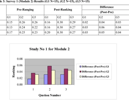
Table 3: Survey 1 (Module 2) Results (G1 N=15), (G2 N=15), (G3 N=15)
Difference Post-Ranking
Pre-Ranging
No (Post-Pre)
G3 G2
G1 G3
G2 G1
G3 G2
G1
0.03 0.04
0.02 0.29
0.30 0.16
0.26 0.26
0.15 1
0.04 0.06
0.03 0.27
0.30 0.16
0.22 0.24
0.13 2
0.04 0.05
0.03 0.27
0.30 0.20
0.23 0.25
0.17 3
Chart 2: Results of Study 1(Module2) (G1 N=15), (G2 N=15), (G3 N=15)
The positive increases in the rankings, for all seven questions in (module1) and three questions in (module2) chart 2, indicate that the student learning outcomes were achieved, at least as self-reported by the students. More importantly, the students listed several common themes about what they liked about the exercises and software used to support their learning:
• They were real-world examples, not abstract. • The software was easy to use and many features
were learned.
• The visualization controls were very useful with computer technology support.
• Easy to follow the task procedure in simulation and computer assisted instruction methods. • Easy to link classroom work during practicing
time in the laboratories.
• Give students opportunities to work extra time with and without teachers’ supervision by using computer guide.
On the contrary, the students in traditional teaching almost commented on the lack of clarity in the writ-ten notes, book, and projector slides which were still in traditional form which affect their results. Nonethe-less, the general tone of the group 2 and 3 students’
written responses was quite positive for this first study.
Student Outcomes Study 2 M 3(Module 3): Assembly, Mating Modelling and
Kinematics Animation
The next survey was conducted for the assembly and mating modelling. The learning objectives for this laboratory exercise were: building multiple 3-D parts that will mate together; starting a new assembly file; dragging and dropping parts into the assembly; moving and rotating components; and mating the parts with different mate types.
an-imation on an external viewer, and then save it in a universal.DXF file format.
[image:8.595.150.429.141.244.2]A typical student exercise consists of building the assembly is shown in Figure 3 before and after mat-ing.
Figure 3: Pulley bracket assembly and Kinematics Animation
For this assembly module, the students learn how to change the colours of the assembly components and how to apply several mate conditions: parallel, con-centric, coincident, and distance. They can also get a colour hardcopy of the whole assembly once the exercise is completed. As before, a pre- and post-survey was conducted for the student learning out-comes (level of understanding) posed by the follow-ing seven concepts:
1. Building individual and multiple parts in 3-D solid modelling and render the part.
2. Building an assembly of parts in 3-D solid modelling.
3. Mating parts in 3-D solid modelling.
4. Check for clearance and interference of parts. 5. Create colour rendering of assembly.
6. Exploding a 3-D assembly of solid model parts. 7. Creating a kinematics animation of a solid
model assembly.
The same ranking scale of 5 (Exceptional) to 1 (None) was used again. Results of the pre- and post ranking averages are shown in Table 4 and in the bar chart No: 3
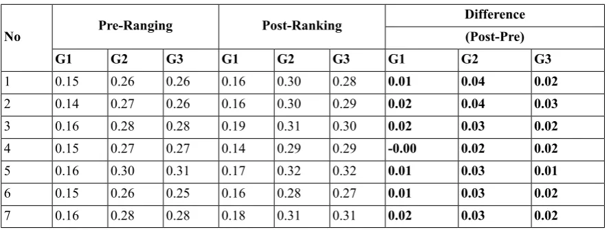
Table 4: Survey 2 (Module 3) Results (G1 N=15), (G2 N=15), (G3 N=15)
[image:8.595.70.515.450.618.2]Chart 3: Results of Study 2 (Module3) (G1 N=15), (G2 N=15), (G3 N=15)
Again the difference between pre- and post- average rankings indicates a positive trend for all seven con-cepts. In particular, the students commented that the exercise was real-life and that they liked assembly, mating modelling and kinematics animation mating for mechanical parts. The results show that most of the students in the group 2 and 3 were familiar with module number 3 because of computer simulation and teacher instruction or computer instruction. In traditional teaching method some students commen-ted about one difficulty that was; it was hard to identify a rotate control function without any guide or support during practice, which is not an intuitive skill for the students. Results of the pre- and post-ranking averages are shown in Table 4 and in chart 4.
Once again, the differences between the pre- and post- average rankings indicate a positive increase in the general learning activities, averaging almost +0.03 point for group 1, +0.05 for group 2, and +0.04 for group 3 increases for all seven questions except question 4 which shows post result lower than the pre result.
It has been noticed that sometimes the students do not have enough knowledge to assemble and mate
the parts since the main teaching method is based on traditional learning. Students do not always have opportunity to work with teacher support.
The students exit comments for this animation study were all very positive.
Student Outcomes Study 3(Module 4): Generating and Dimensioning Three-View Drawings and Section Views in 3-D and 2-D
The third study focused on the need to generate an engineering drawing for final design documentation. The learning activities and objectives for this module included: inserting a drawing sheet onto the screen; setting the drawing sheet options; projecting three orthographic views of a solid model onto a drawing sheet; adding centrelines; dimensioning the drawing; adding title block and annotations; printing the drawing and then save it as DXF file format.
[image:9.595.132.480.85.279.2]A typical student computer modelling exercise is shown in Figure 4, and its projected and dimensioned engineering drawing is shown in Figure 5.
Figure 5: A Dimensioned Drawing of a 3-D Model
The study also focused on the topic of section views, focusing on both 3-D and 2- D techniques.
The pre- and post- surveys for study 3 posed the following eight questions concerning the student’s level of understanding about:
1. Making a 3-D section view of a 3-D solid model.
2. Making a 2-D section view from a 3-D solid model.
3. Detailing a 2-D section view drawing. 4. Arranging the three-view layout on a drawing
sheet.
5. Dimensioning a three-view drawing. 6. Generate suitable drawing sheet style. 7. Add a title block and appropriate notes. 8. Save each part as DXF file.
Results of the pre- and post- ranking averages are shown in Table 5
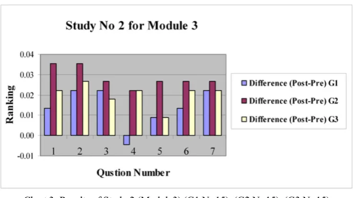
Table 5: Survey 3 (Module 4) Results (G1 N=15), (G2 N=15), (G3 N=15)
Difference Post-Ranking Pre-Ranging No (Post-Pre) G3 G2 G1 G3 G2 G1 G3 G2 G1 0.02 0.04 -0.02 0.27 0.30 0.12 0.25 0.26 0.14 1 0.01 0.02 -0.02 0.29 0.31 0.13 0.28 0.29 0.15 2 0.01 0.02 0.00 0.30 0.32 0.15 0.29 0.30 0.14 3 0.03 0.04 0.00 0.29 0.30 0.17 0.26 0.26 0.17 4 0.02 0.04 -0.02 0.31 0.32 0.14 0.29 0.29 0.16 5 0.02 0.03 0.00 0.31 0.31 0.16 0.29 0.28 0.16 6 0.01 0.02 0.01 0.32 0.32 0.19 0.30 0.30 0.18 7 0.01 0.01 0.01 0.33 0.33 0.29 0.32 0.32 0.28 8
[image:10.595.71.515.376.759.2]Again, the differences between the pre- and post-average rankings indicate a positive increase in the general learning activities in simulation and computer assisted instruction (group 2 and 3), although it may not be as the differential as in previous studies.
The students in group 2 and 3 were generally re-ceptive to learning activity, even though they realized that making an engineering drawing is relegated to a secondary role in the modern concurrent engineer-ing paradigm. They frequently commented on the “ease” of creating three-views from a solid model with the current software. They also felt that the last two modules reinforced the basic concept of deriving design documentation from a solid model, rather than creating the documentation from scratch. The one consistent negative comment was the degree of difficulty in applying details to the final engineering drawing, particularly in placing centrelines and in deciding which dimensions to select. The final comment was that the software packages able to de-velop student's skills and improve learning experi-ence.
On the other hand the group 1 students (traditional teaching) comment was difficult to develop their knowledge in complex drawing specially in learning outcome 1, 2, and 5 as ranking result shown in table 5 and chart 4.
Saving their work as DXF file that could be played externally, this was particularly gratifying since none of them had ever made a DXF file before. The instruc-tions were easy to follow, due mainly to the" Anim-ation Wizard” and accompanying tools that were available in the software.
Student Outcomes Study4 (Module5): Rapid Prototyping
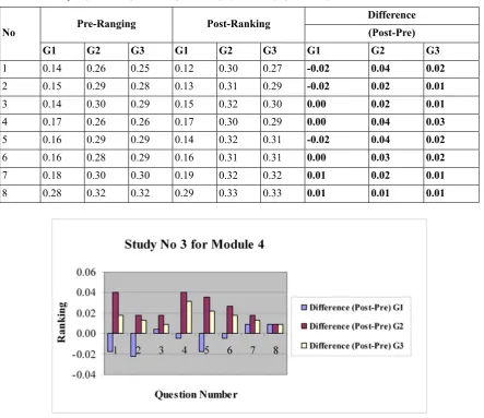
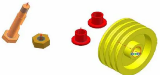
[image:11.595.168.438.371.497.2]The fourth study was conducted during the rapid prototyping lab exercise. The learning activities for this module included: building a solid part; creating NC file from the solid model data; transferring the DXF file to a rapid prototyping machine as NC file; and completing the rapid prototype. Some example parts used as student exercises for this module are shown in Figure 6.
Figure 6: Rapid Prototypes of Student Parts
The pre- and post- surveys posed the following elev-en questions concerning the studelev-ent’s level of under-standing about:
1. Generating DXF and NC file from a 3-D solid model.
2. Building a rapid prototype of a 3-D solid model. 3. The role of rapid prototyping in the design
process.
4. Create cutting parameter for each part (cutting tool, tool size, tool materials, and work materi-als).
5. Generate tool paths for different layers for each part (X, Y, Z direction, cutting loop, and depth of cut, feed and speed).
6. Save each part as numerical control (NC) file and send the file to the prototyping machine. 7. Set the work piece; set the tool at zero position. 8. Check direction of rotation for the chuck and the cutter; check the work piece and the cutting tool are securely clamped.
9. Verify the NC program for simple shaft com-plex prototype.
10. Simulate the motion of assembly file. 11. Run the machine and then the program.
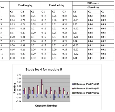
Table 6: Study 4 (Module 5) Results (G1 N=15), (G2 N=15), (G3 N=15) Difference Post-Ranking Pre-Ranging No (Post-Pre) G3 G2 G1 G3 G2 G1 G3 G2 G1 0.03 0.03 0.02 0.28 0.28 0.18 0.25 0.25 0.16 1 0.02 0.04 -0.03 0.27 0.28 0.12 0.24 0.24 0.14 2 0.03 0.04 0.02 0.31 0.31 0.16 0.28 0.28 0.15 3 0.04 0.04 -0.02 0.25 0.25 0.12 0.21 0.21 0.14 4 0.05 0.08 0.01 0.25 0.28 0.12 0.20 0.20 0.11 5 0.01 0.02 -0.01 0.32 0.33 0.19 0.31 0.31 0.20 6 0.02 0.04 0.00 0.28 0.29 0.13 0.26 0.26 0.13 7 0.01 0.02 -0.03 0.32 0.33 0.17 0.31 0.31 0.20 8 0.02 0.04 -0.02 0.28 0.29 0.14 0.26 0.26 0.16 9 0.02 0.03 -0.02 0.31 0.32 0.16 0.29 0.29 0.18 10 0.01 0.01 0.00 0.33 0.33 0.30 0.32 0.32 0.30 11
Chart 5: Results of Study 4 (Module5) (G1 N=15), (G2 N=15), (G3 N=15)
Once again, the differences between the pre- and post- average rankings indicate a positive increase in the general learning activities, averaging around +0.03 point for group 2 ( computer assisted instruc-tion) and +0.02 point for group 3 ( computer simula-tion) increase for all eleven questions.
In general, the students enjoyed this module even though it was time-consuming due to the manual assembly requirements of the rapid prototyping sys-tem. They clearly enjoyed building a real part when they tried to match with a computer model. As one student simply stated, “seeing the computer sketches turning to an actual model was very impressive.” Most of the students in this module said that the computer assisted instruction software gives oppor-tunity to deal with complex components with simplest methods.
Around -0.01 point the average, indicate negative results obtained from eleven question of prototype
module for traditional teaching method. The students commented with main points about the negative results of this module saying “The student's attention in the classroom was not there, there was no motiva-tion for the students to create their interest in the subject matter and develop positive attitude toward learning”. To manufacture mechanical components in the work shop need student’s attention all the time for interactive knowledge.
Student Outcomes Study 5(Module 6): Project and Analysis (manufacturing)
aided drawing (CAD). The next stage was to build real mechanical components in the lab.
They assigned different type of measurements with different measuring tools to compare between engineering drawing sheet and the real components. The checklist for the drawing is always available to show the areas that need improvement in the shaft
[image:13.595.191.419.179.286.2]and gear design. The students then complete the ex-ercise by modifying the design. In this case, they need to repeat the above procedure to improve man-ufacturing design. Some example parts used as stu-dent exercises for this module are shown in Figure 7.
Figure 7: Manufacturing component (Shaft and Gear)
The pre- and post- surveys posed the following four questions concerning the students’ level of under-standing about:
1. Generate final checklist for dimensions. 2. Generate final checklist for assembly.
3. Generate final checklist for motion.
4. Generate final checklist for tolerance and fit.
Results of the pre- and post ranking averages are shown in Table 7 and in the bar chart No 6.
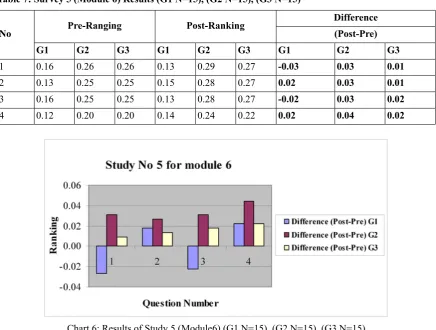
Table 7: Survey 5 (Module 6) Results (G1 N=15), (G2 N=15), (G3 N=15)
Difference Post-Ranking
Pre-Ranging
No (Post-Pre)
G3 G2
G1 G3
G2 G1
G3 G2
G1
0.01 0.03
-0.03
0.27 0.29
0.13 0.26
0.26 0.16
1
0.01 0.03
0.02
0.27 0.28
0.15 0.25
0.25 0.13
2
0.02 0.03
-0.02
0.27 0.28
0.13 0.25
0.25 0.16
3
0.02 0.04
0.02
0.22 0.24
0.14 0.20
0.20 0.12
4
Chart 6: Results of Study 5 (Module6) (G1 N=15), (G2 N=15), (G3 N=15)
Again, the differences between the pre- and post-average rankings indicate a positive increase in the
[image:13.595.88.525.402.732.2]the context of exercise as self-reported by the stu-dents).
The average ranking indicate a positive increase in the learning activities averaging around +0.03 point for group 2 (computer assisted instruction) and +0.02 point for group 3 (computer simulation) in-crease for all the four questions.
The group 2 and group 3 students mentioned that the teaching methodology gives opportunities to un-derstand the following aspects:
• The need to carry out many design tasks system-atically and that design of the manufacturing process should be carried out in parallel with drawing analysis.
• Produce and more importantly read fully detailed engineering drawing and manufacturing, dimen-sions, assembly, motion, and tolerance and fit using engineering checklist.
• The need to search may obtain skills and inform-ation appropriate to the task under considerinform-ation in which student may not possess ability of ana-lysis.
• Analyse a product and subdivide it to produce a product structure upon which drawing set and task allocation may be based..
• Read fully detailed engineering drawing and diagrams.
Also for this study, the students offered the following favourable comments:
• The visualization of detailed engineering drawing and manufacturing, dimensions, assembly, mo-tion, and tolerance and fit using engineering checklist as results was great.
• Seeing the assembly, motion, and tolerance and fit using engineering checklist was helpful to understand the study.
• Very real-like engineering design example.
The main negative comment seemed to be amongst the students in the traditional teaching: the wasting time behind the finite element method which re-mained elusive to them after the exercise was over, even though they did not see the potential for its ap-plication or understand the way of analysis with checklist. One student commented while leaving the
room: “This was a great exercise, but I still don’t know what I did.” This aspect of the manufacturing module needs to be improved as these types of ad-vanced topics are introduced in the course. To achieve good ranking and to increase average from low rank to high rank, the method of teaching and learning should be improved.
Comparison of Six Module of Student Learning Outcomes Surveys
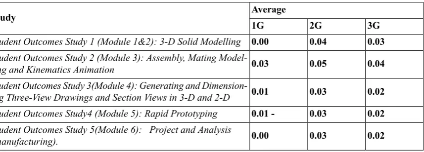
All six module student learning outcomes surveys showed a positive trend in learning, based on self reported pre- and post- module exercise surveys. This is to be expected, since the students gained some additional knowledge and skills doing each exercise, and appropriately reported that in the surveys. Table 8 lists the average pre- to post- increases.
Table 8: Average Pre- to Post Increases
Average Study
3G 2G
1G
0.03 0.04
0.00 Student Outcomes Study 1 (Module 1&2): 3-D Solid Modelling
0.04 0.05
0.03 Student Outcomes Study 2 (Module 3): Assembly, Mating Model-ling and Kinematics Animation
0.02 0.03
0.01 Student Outcomes Study 3(Module 4): Generating and Dimension-ing Three-View DrawDimension-ings and Section Views in 3-D and 2-D
0.02 0.03
0.01 -Student Outcomes Study4 (Module 5): Rapid Prototyping
0.02 0.03
0.00 Student Outcomes Study 5(Module 6): Project and Analysis
(manufacturing).
Conclusions
The mechanical engineering “Engineering Drawing and manufacturing” curriculum has evolved continu-ously to present system in which Computer aided drawing CAD, Computer aided manufacturing CAM and computer numerical control CNC, are at the centre of instruction system. Table 1 lists a sequence of engineering CAD/CAM/CNC learning modules that systematically introduce the students to this new engineering drawing and manufacturing paradigm.
Pre and post surveys have been used to present the results of systematic assessment of the learning outcomes of this new approach to “Mechanical En-gineering Drawing and manufacturing.” Three teaching method and two types of assessment were conducted. Specific learning activities for six draw-ing and manufacturdraw-ing modules were identified and formulated into a set of surveys. The surveys were conducted in three selected sections of the mechan-ical engineering (CAD/CAM/CNC) course using self-reported pre- and post-study rankings.
In all cases, the difference between the post and pre- ranking score, deemed improvement in learning, showed a positive trend in group 1 and 2. This indic-ates that all the drawing and manufacturing activities resulted in a positive learning experience on the part of the students and the highest values of the most learning outcomes were obtained in groups 2 and 3 (simulation teaching method and computer assisted instruction method).
Also it has been seen that the group (2) exposed to computer assisted instructions performed much better than the group exposed to traditional teaching. Further computer assisted instruction helped students with widely varying pre-learning abilities to satisfy various learning outcomes in CAD/CAM/CNC sub-ject area.
Acknowledgement
The authors wish to acknowledge the support from Ministry of Education Kingdom of Bahrain and School of Computing and Engineering, University of Huddersfield.
References
1-James E.Gall. 2001-2002. Rethinking the computer in education. J, Educational Technology systems, 30(4), 379-388.
2-Suresh K. Bhavnani and Bonnie E. John - Carnegie Mellon University, 2000.The strategic use of complex computer systems. Human-Computer interaction,15,107-137.
3-R.C.F. Dye. 2003. A computer generated Pseudo-Experiment in fluid mechanics. The international Journal of Mech. Engineering education, 31(2),143-149.
4-Van Dijk L.A ; Van Der Berg G.C ; Van Keulen H. 2001. Interactive lecture in engineering education. European Journal of engineering Education, 26(1),15-28.
5-Marcy J.Wang, M.A , Paul B.Contino,M.A , Edwin S. Ramirez,B.S Gustave L, and Janet W.Levy. 2000. Implementing cognitive learning strategies in computer-based educational technology. New York, New York.
6-Caroline Baillie & Ivan Moore. 2004. Effective learning & teaching in engineering USA, Canada
7-J.Bourne, A Brodersen, M.Daw. 2000. The influence of technology on Engineering Education. NewYork, London, Tokyo
8-Ton de Jony and Luigi Sarti. 1994. Design and Production of Multimedia and Simulation-Based Learning Material. Netherlands.
9-A.H. Maslow, Motivation and Personality (3rd Edition). New York: Harper Collins Publishers,1970.
10-F.T. Lee, Journal of Institution of Engineers, Malaysia, Vol. 58, No. 4, 1997, pp. 51-57.
11-J.A. Smith, K. Baker & S. Higgins, EOQ '93 World Quality Congress Proceedings, Helsinki, Finland, (1993).
12-R. Zaciewski, Improving the instructional process. Quality Process, April 1994, pp. 75-80.
14-Salah Mahdi Abdulrasool, Rakesh Mishra, John Fieldhouse, Steve Ward. 2006. Effectiveness of Parallel and Serial In-tegration of Teaching Resources in Laboratory Teaching in Engineering Education The International Journal of Learning ( www.learning-journal.com)
15- Salah Mahdi Abdulrasool, Rakesh Mishra, John Fieldhouse, John McComish, Steve Ward. 2007. Effectiveness of Computer Assisted Laboratory Instructions: Learning Outcomes Analysis The International Journal of Learning (www.learning-journal.com).
About the Authors
Salah Mahdi Abdulrasool
Mr. Abdulrasool is a Ph.D. student in School of Computing and Engineering, University of Huddersfield, U.K. He has an academic career spanning 23 years. Mr Abdulrasool worked as lecturer, senior teacher, advisor, quality manager, moderator and technical education specialist in various departments within the directorate of Technical and Vocational education in the Kingdom of Bahrain. Currently he is chief of Center of Excellence for Technical and Vocational Education - Kingdom of Bahrain. He holds an Honours degree in engineering with technology Management as well an M.Phil degree in Engineering.
Dr. Rakesh Mishra
Bill Cope, University of Illinois, Urbana-Champaign, USA.
Mary Kalantzis, University of Illinois, Urbana-Champaign, USA.
EDITORIAL ADVISORY BOARD
Michael Apple, University of Wisconsin-Madison, USA.
David Barton, Lancaster University, UK.
Mario Bello, University of Science, Technology and Environment, Cuba.
Robert Devillar, Kennesaw State University, USA.
Manuela du Bois-Reymond, Universiteit Leiden, Netherlands.
Ruth Finnegan, Open University, UK.
James Paul Gee, University of Wisconsin-Madison, USA.
Kris Gutierrez, University of California, Los Angeles, USA.
Anne Hickling-Hudson, Queensland University of Technology, Kelvin Grove, Australia.
Roz Ivanic, Lancaster University, UK.
Paul James, RMIT University, Melbourne, Australia.
Carey Jewitt, Institute of Education, University of London, UK.
Andeas Kazamias, University of Wisconsin, Madison, USA
Peter Kell, University of Wollongong, Australia.
Michele Knobel, Montclair State University, New Jersey, USA.
Gunther Kress, Institute of Education, University of London.
Colin Lankshear, James Cook University, Australia.
Daniel Madrid Fernandez, University of Granada, Spain.
Sarah Michaels, Clark University, Massachusetts, USA.
Denise Newfield, University of Witwatersrand, South Africa.
Ernest O’Neil, Ministry of Education, Addis Ababa, Ethiopia.
José-Luis Ortega, University of Granada, Spain.
Francisco Fernandez Palomares, University of Granada, Spain.
Ambigapathy Pandian, Universiti Sains Malaysia, Penang, Malaysia.
Miguel A. Pereyra, University of Granada, Spain.
Scott Poynting, University of Western Sydney, Australia.
Angela Samuels, Montego Bay Community College, Montego Bay, Jamaica.
Juana M. Sancho Gil, University of Barcelona, Spain.
Michel Singh, University of Western Sydney, Australia.
Helen Smith, RMIT University, Australia.
Richard Sohmer, Clark University, Massachusetts, USA.
Pippa Stein, University of Witwatersrand, South Africa.
Brian Street, King's College, University of London, UK.
Giorgos Tsiakalos, Aristotle University of Thessaloniki, Greece.
Salim Vally, University of Witwatersrand, South Africa
Gella Varnava-Skoura, National and Kapodistrian University of Athens, Greece.
Cecile Walden, Sam Sharpe Teachers College, Montego Bay, Jamaica.
Nicola Yelland, Victoria University, Melbourne, Australia.
Wang Yingjie, School of Education, Beijing Normal University, China.
Zhou Zuoyu, School of Education, Beijing Normal University, China.
ISSN: 1833-1866
http://www.Arts-Journal.com
International Journal of the Book
Explores the past, present and future of books, publishing, libraries, information, literacy and learning in the information society. ISSN: 1447-9567
http://www.Book-Journal.com
Design Principles and Practices: An International Journal
Examines the meaning and purpose of ‘design’ while also speaking in grounded ways about the task of design and the use of designed artefacts and processes. ISSN: 1833-1874
http://www.Design-Journal.com
International Journal of Diversity in Organisations, Communities and Nations
Provides a forum for discussion and builds a body of knowledge on the forms and dynamics of difference and diversity. ISSN: 1447-9583
http://www.Diversity-Journal.com
International Journal of Environmental, Cultural, Economic and Social Sustainability
Draws from the various fields and perspectives through which we can address fundamental questions of sustainability. ISSN: 1832-2077
http://www.Sustainability-Journal.com
Global Studies Journal
Maps and interprets new trends and patterns in globalization. ISSN 1835-4432
http://www.GlobalStudiesJournal.com
International Journal of the Humanities
Discusses the role of the humanities in contemplating the future and the human, in an era otherwise dominated by scientific, technical and economic rationalisms. ISSN: 1447-9559
http://www.Humanities-Journal.com
International Journal of the Inclusive Museum
Addresses the key question: How can the institution of the museum become more inclusive?ISSN 1835-2014
http://www.Museum-Journal.com
International Journal of Interdisciplinary Social Sciences
Discusses disciplinary and interdisciplinary approaches to knowledge creation within and across the various social sciences and between the social, natural and applied sciences.
ISSN: 1833-1882
http://www.Socialsciences-Journal.com
International Journal of Knowledge, Culture and Change Management
Creates a space for discussion of the nature and future of organisations, in all their forms and manifestations. ISSN: 1447-9575
http://www.Management-Journal.com
International Journal of Learning
Sets out to foster inquiry, invite dialogue and build a body of knowledge on the nature and future of learning. ISSN: 1447-9540
http://www.Learning-Journal.com
International Journal of Technology, Knowledge and Society
Focuses on a range of critically important themes in the various fields that address the complex and subtle relationships between technology, knowledge and society. ISSN: 1832-3669
http://www.Technology-Journal.com
Journal of the World Universities Forum
Explores the meaning and purpose of the academy in times of striking social transformation.
ISSN 1835-2030
http://www.Universities-Journal.com
FOR SUBSCRIPTION INFORMATION, PLEASE CONTACT