2016 6th International Conference on Information Technology for Manufacturing Systems (ITMS 2016) ISBN: 978-1-60595-353-3
1. INSTRUCTION
China has a vast territory; the geological conditions vary widely in various regions. The transmission line based on the use of the form is also more diverse. In the design of tower foundation, the cross foundation (Figure 1 shows) is combined independent foundations under the 4 legs of tower into a whole, and though the cross beam passing the upper and lower pressure. Load passed to the ground through foundation, and the internal stress changes after the ground bearing load. On the one hand, the additional stress causes the deformation of the soil, which causes the foundation settlement. On the other hand, the shear stress of soil is increased. The damage of the soil is usually caused by the shear damage, and the shear zone is often formed in the process of the damage. When the shear stress of a certain point reaches the shear strength of the soil, the soil is in the limit equilibrium state. soil parameters have a very important influence on the change of bearing capacity, the ultimate bearing capacity of foundation under different shear strength index is also different. The soil parameters in the cohesion c and internal friction angle φ are two important indexes. For nearly half a century, a large number of scholars have studied the ultimate bearing capacity of the tower foundation, there are three methods, such as model test, limit equilibrium
analysis, numerical simulation. This paper use ABAQUS finite element simulation software to analysis the ultimate bearing capacity of crossed foundation of internal friction angle and cohesive force in different conditions. Analysis of ground failure process, to obtain the ultimate bearing capacity of the foundation. Comparison of Hansen's theory formula and numerical simulation results of ultimate bearing capacity, analyze the causes of error and put forward the concept of correction coefficient and propose more reasonable foundation ultimate bearing capacity theory formula.
2. INTRODUCTION AND MODELING OF CROSS FOUNDATION
2.1 Structural forms and characteristics
The so-called cross foundation, the most distinctive feature is the two beam cross layout, It is similar in form to the foundation of the united, common point is the four independent foundation to connect into a whole, The difference is the load is to withstand the combined foundation slab, then the load on the beam transmission, and cross foundation is based on the foundation beam to bear the load, the beam under the board is to meet the foundation bearing capacity of the set, the beam is the main body. Compared to
Study on The Ultimate Bearing Capacity of Cross Foundation under
Horizontal Loading Mode
Chuncheng Liu, Fuda Liu, Chuanming Zha, Xiaopan Zhao
Northeast Dianli University Institute of Civil Engineering, Jilin, ChinaABSTRACT: The cross foundation as a special form of the overhead transmission line tower foundation, which has a buried depth, high reliability, good integrity, resistance to horizontal displacement ability characteristics. Research the ultimate bearing capacity of the foundation that based on the limit equilibrium principle in the M-C constitutive model under the condition of horizontal load. The process of deformation, development and damage of foundation after loading is simulated, the influence of friction angle and cohesive force on the bearing capacity of the foundation is analyzed, and drawn the P-S curve. According to the theoretical formula of the ultimate bearing capacity of Hansen and the numerical simulation results, analyzed the reason of the difference and proposed the concept of the correction factor. The results show that the numerical simulation results well reflect the whole process of foundation deformation and failure, the effect of friction angle and cohesion on the bearing capacity of foundation is visual. The Hansen theoretical formula is too conservative to a certain extent, the modified formula of ultimate bearing capacity is proposed, which provides a reference for the application of cross foundation in transmission line engineering.
cross foundation, combined foundation often requires a greater amount of earthwork excavation and reinforcement. The three dimensional schematic diagram of the cross foundation is shown in Figure 1.
Figure 1. The diagram of the cross foundation. 2.2 Finite element model
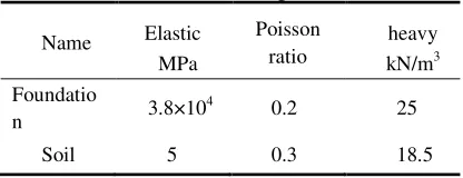
[image:2.612.388.505.257.329.2]The cross foundation material is reinforced concrete. The assumption that the foundation of the load range does not damage. The model is based on elastic model, and the elastic modulus is E=38000MPa, Based on the ideal elastic-plastic constitutive relation, which is based on the Molar Culun yield criterion, the mechanical parameters of each material are shown in Table 1.
Table 1. Mechanical parameters.
Name Elastic MPa
Poisson
ratio heavy kN/m3
Foundatio
n 3.8×10
4 0.2 25
Soil 5 0.3 18.5
The foundation and soil model are used in the design parameters of the actual engineering. The length is 13.8m, width is 2.1m, and height is 1.5m, deep 2.5m in the soil. The soil depth is 10m, and the transverse length is 5 times longer than beam foundation, and the model is 80m×80m×10m. Such a region can remove the affect of boundary effect on the calculation results. In the model, the freedom in x, y, z directions on the bottom surface are are restricted. the constraint conditions of the two sides of the model are U1=UR2=UR3=0, the constraints on the left and right sides are U1=U3=UR2=0. The cross foundation and the soil foundation uses the “tie” contact. Finite element mesh choose three-dimensional solid element, and foundation and the soil are used C3D8R eight node hexahedral linear reduced integral unit. The three-dimensional model and the finite element mesh are shown in Figure 2.
Figure 2. Finite element model and mesh division.
3. NUMERICAL ANALYSIS
3.1 Research theory and criterion
The ground bearing capacity is the load on the foundation of the unit area. Is an important part of the foundation design, the research methods are: model test, limit analysis and limit equilibrium method and finite element numerical analysis method.
In this paper, the coupling reference point is set up in the center of four bases, and the load is applied to the reference point, as shown in figure 3. The load displacement curve of the foundation is obtained. Until the slope of the curve is close to that of the infinite, according to the concept of ideal plastic flow, the corresponding load can be used as the ultimate load.
Figure 3. The coupling reference point on the base column.
The load displacement curves can be divided into two types, namely variant steep and variant. In the steep deformation, there is a second inflection point, which can be used as the ultimate load of the ground. In the slowly varying curve, there is no obvious second turning point, it is necessary to determine the limit load of the foundation according to the settlement. When the horizontal bearing capacity is used, Hansen considers that the maximum horizontal displacement of the foundation is 6% to 3% of the foundation width as the failure criterion of horizontal displacement.
3.2 Analysis of ultimate bearing capacity of foundation under horizontal load
Foundation in under the action of horizontal load behavior is more complex, long-term since most people tend to focus on basic research in under the action of vertical load performance, however, there are few studies under the horizontal load.To ensure the foundation under horizontal load can normal work should meet: the surrounding soil of the foundation under horizontal load is extruded but did not because the foundation displacement is too and enter the fully plastic state, namely most soils should work at elastic state. In this paper, in order to study soil parameters of crossed foundation when subjected to horizontal load bearing characteristics influence, according to the stipulated in the overhead power transmission lines based technical design specification of clay soil parameters selection of soil parameters was studied by numerical simulation,
[image:2.612.73.281.336.416.2]draw the load settlement curve, judge the foundation of the limit bearing capacity.
3.3 Influence of internal friction
Numerical simulation of cohesion c=12kPa, 20 kPa, 32kPa, 40kpa ang inner friction angle φ = 10°,
15°, 20°, 25°of limit bearing capacity and plotted load - displacement curve.
(a) c =12kPa (b) c=20kPa
[image:3.612.315.549.103.257.2](c) c=32kPa (d) c=40kPa
Figure 4. The displacement curve.
In condition of keeping the cohesion unchanged, the foundation under horizontal load of load - displacement curve with the friction angle changes and changes the trend. As shown in Figure 4. Other factors remain unchanged, when the cohesion is 12kPa, 20kPa, 32kPa, 40kPa, ultimate bearing capacity will increases with the increase of the friction angle. In the applied load at the beginning of a period of time, the four curves have obvious separation phenomenon, this phenomenon in cohesion 40kpa and 32kPa gradually disappeared, almost being one curve, with further increase of the load the curve separate again. That in cohesion is relatively small, friction angle of foundation bearing force effect more obvious, and with the cohesion increases, the influence of friction angle increases with the increase of load.
Figure 5. The effect of internal friction angle on the vertical ultimate bearing capacity.
Figure 5 shows through the horizontal load foundation ultimate bearing capacity criteria
settlement under 3% of the width of the foundation to determine the ultimate load. The ultimate bearing capacity of the foundation increases linearly with the increasing of the internal friction angle when the cohesive is constant.
(a) The effective yield point of foundation without horizontal load
(b) The effective yield point when the ultimate bearing capacity is reached
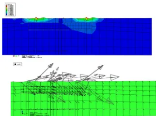
Figure 6. The effective yield point cloud image of the foundation under horizontal load.
As shown in Figure 12, the internal friction angle is 10 degrees, cohesion is 20kPa based respectively in no bearing horizontal load and bearing horizontal load reaches the ultimate bearing capacity, effective yield point cloud of soil around the foundation. As is shown in the figure, when the horizontal load is not applied, the ground is only subjected to the gravity of the foundation and soil, and the effective yield point exists only in the small area under the foundation. When the horizontal load is applied to the foundation and the ultimate bearing capacity is reached, the effective yield area of the soil mass is enlarged, and on the side of the horizontal load direction (the lower right side of foundation area) is more concentrated, It shows that under the pressure of the right lower part of the foundation soil, there is a large plastic strain zone.
Figure 7. The displacement contour of the foundation under horizontal load.
As shown in Figure 13, the internal friction angle is 10°, cohesion is 20kPa ,the displacement of foundation under horizontal load. From the figure, the foundation bearing horizontal load and soil
0 500 1000 1500 2000 0
20 40 60 80 100
位 位
(
m
m
)
荷载 (KN)
φ=10°
φ=15°
φ=20°
φ=25°
0 500 1000 1500 2000 0
20 40 60 80 100
位 位
(
m
m
)
荷载 (KN)
φ=10°
φ=15°
φ=20°
φ=25°
0 500 1000 1500 2000 0
20 40 60 80 100
位 位 (
m
m
)
荷 载 (KN)
φ=10°
φ=15°
φ=20°
φ=25°
0 500 1000 1500 2000 0
20 40 60 80 100
位 位
(
m
m
)
荷 载 (KN)
φ=10°
φ=15°
φ=20°
φ=25°
0 10 20 30
0 500 1000 1500 2000
荷 载
(
K
n
)
内内内内φ (°)
c=12KPa c=20KPa c=32KPa c=40KPa
[image:3.612.69.284.137.318.2] [image:3.612.356.517.540.660.2] [image:3.612.121.247.590.680.2]gravity can be viewed as similar by a tilt angle force and cause displacement. The displacement under the lower right side of foundation is more concentrated, in this area can be regarded as the rotation point. under ideal conditions, the foundation will be rotated around the point. But due to the cross foundation is relatively shallow, belong to shallow foundation type and cross beam height restrictions, so the effect of rotation is not obvious, but from the displacement vector map can see this trend with point to rotate. 3.4. Influence of cohesion
(a)φ=10° (b)φ=15°
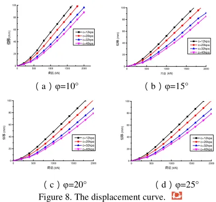
[image:4.612.65.283.183.387.2](c)φ=20° (d)φ=25°
Figure 8. The displacement curve.
From figure 8, the slow change curve is no obvious second inflection point, then to determine the bearing capacity of the foundation settlement limit. The ultimate bearing capacity of the cross foundation will become larger with the increase of the cohesion.
Figure 9. The effect of cohesion on the vertical ultimate bearing capacity.
As shown in figure 9. It can be seen that with the increase of the cohesion, the bearing capacity of the foundation increases linearly. At the time of greater than 30kPa, the growth trend of the ultimate horizontal bearing capacity of the foundation appears slight fluctuation, and the effect of the cohesive strength on the ultimate bearing capacity of the foundation is gradually reduced.
4. COMPARATIVE ANALYSIS OF HANSEN FORMULA AND NUMERICAL SIMULATION
[image:4.612.368.503.245.314.2]The foundation bearing capacity is the ultimate pressure of the foundation load, The solution is based on the limit equilibrium theory and boundary condition, calculate the stress and the sliding direction of each point in the process; The other is to obtain the ultimate bearing capacity according to the static equilibrium condition of the sliding mass. Hansen believes that the size of the ultimate bearing capacity is based on the size and angel of inclined load. According the translation principle of force, the vertical and horizontal loads can be combined to form an inclined load. The vertical and horizontal loads were inclined load force in the vertical and horizontal direction. As shown in figure 10.
Figure 10. Load decomposition diagram.
Hansen recommended for homogeneous foundation, the base is completely smooth, the ultimate bearing capacity can be calculated by the following formula: γ γ γ γ γ γ
γbNSdigb
b g i d S qN b g i d S cN
pu c c cc cc q q qq q q
2 1 + +
=
formula:Sc、Sq 、Sγ— foundation shape factor;
ic、iq、iγ— load tilt factor;
dc、dq、dγ—depth coefficient;
gc、gq、gγ— foundation slope factor;
bc、bq、bγ— base tilt factor;
Nc、Nq、Nγ— factor of capacity; c— cohesion(kPa);
b、d — width and depth of base(m); q — load(kPa), q=γ0d。
When φ=20°, c=20kPa, Nc=16.7, Nq=7.7, Nγ=4.0;
Chose FV=17000kN, FH=200kN; ic=iq=iγ=1; Sc=Sq=Sγ=1; gc= gq= gγ=bc=bq=bγ=1; dc= dq= dγ=1.
Chose ratio of clay k=3.0, the ultimate bearing
capacity calculated by the theoretical formula is
pu/k=261.6kPa, and the ultimate bearing capacity of
numerical simulation is 377.9kPa. There is a large error between the them, because there is no consideration of the shear strength of the base soil and other soil interaction, so the results of theoretical calculations under this assumption is not very accurate. By comparing the results of Hansen theory
0 500 1000 1500 2000 0 20 40 60 80 100
位 位
(
m
m
)
荷载 (kN)
c=12kpa c=20kpa c=32kpa c=40kpa
0 500 1000 1500 2000 0 20 40 60 80 100
位 位
(
m
m
)
荷载 (kN)
c=12kpa c=20kpa c=32kpa c=40kpa
0 500 1000 1500 2000 0 20 40 60 80 100
位 位
(
m
m
)
荷载 (kN)
c=12kpa c=20kpa c=32kpa c=40kpa
0 500 1000 1500 2000 0 20 40 60 80 100
位 位
(
m
m
)
荷载 (kN)
c=12kpa c=20kpa c=32kpa c=40kpa
0 10 20 30 40 50 60 0
500 1000 1500 2000
荷 载
(
k
N
)
黏黏黏c (kpa)
φ=10° φ=15° φ=20° φ=25°
[image:4.612.113.245.483.583.2]and numerical simulation, the correction coefficient of the ultimate bearing capacity of the cross foundation is proposed.
4 . 1 6 . 261
9 . 377
0 = =
k
The correction coefficient k0 is introduced, and
the theoretical formula of Hansen is modified. The modified formula is as follows:
γ γ γ γ γ γ
γbNS d i gb
b g i d S qN b g i d S cN p
k u c c cc c c q q qq q q 2
1 1
0
+ +
=
5. CONCLUSION
The main object of this paper is the ultimate bearing capacity of the cross foundation. Through the ABAQUS finite element simulation software to simulate the cross foundation and the soil, the soil damage process under different horizontal load levels is studied. And the influence of internal friction angle on the bearing capacity of the foundation is analyzed. By comparing the results of numerical simulation and theoretical formula, the following conclusions can be concluded:
(1)Cross foundation as a model of transmission tower foundation form, by numerical simulation in the limit under different load combination bearing capacity. It is proved that it has good application value in the foundation of transmission line engineering; provide the basis for the extensive application in the future.
(2)The internal friction angle and Cohesion are important parameters which affect the ultimate bearing capacity of foundation, and the ultimate bearing capacity of the foundation increases with the increase of the friction angle of the soil.
(3)The concept of the modified coefficient of the ultimate bearing capacity of the cross foundation is proposed, and the theoretical formula is modified to obtain a reasonable theoretical formula of the ultimate bearing capacity.
(4) With the aid of ABAQUS software, the finite element numerical simulation analysis method could be used to calculate and analyze the practical problems of geotechnical engineering effectively.
REFERENCES
[1] Cheng Yongfeng, Shao Xiaoyan, Zhu Quanjun. The Current Situation and Existing Problems of China's Transmission Lines [J]. Electric Power Construction, 2002, (03):32-34.
[2] Zhang Huaying, Jiang Hongxi. Self Balanced Cross Foundation of Transmission Line [J]. Electric Power Construction.2011, 32 (05): 53-57.
[3] Zhan Yungang, Yuan Fanfan, Luan Maotian, Sun Yanqing. A Numerical Study on the Ultimate Bearing Capacity Coefficient of the Buried Deep Strip Foundation in Homogeneous Soil [J]. Journal of Rock Mechanics and Engineering, 2008, (S2): 3408-3415.
[4] Yan Furong, Fan Wen, Wang Yong, He Yinting. Damage Model Test of Strip Foundation in Soil Foundation [J]. Journal of Disaster Prevention and Mitigation Engineering, 2010, (02): 159-164.
[5] Li Yangyi. Analysis and Research on The Indoor Model Test of The Reinforced Foundation in Sand [D]. Tongji University, 2006.
[6] Hu Hong. Research on the Bearing Capacity and Failure Mechanism of Strip Anchor Plates in Sand Soil Foundation [D]. Dalian University of Technology, 2013.
[7] Zhao Chenggang. Discussion on the Present Situation of Soil Mechanics and Some Problems in Numerical Analysis Method [J]. Rock and Soil Mechanics, 2006, (08): 1361-1364.
[8] Wang Jinchang, Zhu Xiangrong. Introduction and Application of ABAQUS Software in Some Soil Models [J]. Rock and Soil Mechanics, 2004, (S2): 144-148. [9] Liu Shitao, Cheng Peifeng. Constitutive Model for
Numerical Analysis of Soil Mass Based on ABAQUS [J]. Low Temperature Construction Technology, 2010, (02): 90-92.
[10] Han Dong Dong. Study on Ultimate Bearing Capacity of Strip Shallow Foundation [D]. Zhejiang University, 2007.