2019 International Conference on Computational Modeling, Simulation and Optimization (CMSO 2019) ISBN: 978-1-60595-659-6
Lightning Protection of ± 500 kV Three-circuit Direct Current Overhead
Transmission Lines on the Same Tower
Di GAO
1, Jun LU
2and Shi-li LIU
1,*1School of Electrical Engineering, Northeast Electric Power University, Jilin 132012, China
2State Power Economic Research Institute, Beijing 102209, China
*Corresponding author
Keywords: Direct current, Three-circuit cines on the same tower, Lightning protection, Transmission line.
Abstract. The three-circuit flexible DC transmission line in the same tower has great advantages in saving transmission corridors, but its lightning protection design is obviously different from single-circuit or double-return overhead lines. Especially in the case of forming a DC grid, the striking flashover rate should be strictly controlled. For this reason, the lightning withstand performance of ±500kV three-circuit flexible DC transmission lines arranged on the same tower is analyzed by using electrical geometric model and traveling wave method. With such method and model the effect of polar line arrangement, grounding resistance, tower height on the lightning protection are analyzed. The computational results prove that when the lightning protection angle of overhead ground wire is designed to be -14° and the recommended E layout scheme is adopted for the pole conductor, the striking flashover rate can be controlled to be less than 0.1 times/(100km·a). The research results lay the foundation for the lightning protection design of the ±500kV three-circuit flexible DC lines arranged on the same tower.
Introduction
Compared with single and double circuits, ±500kV three-circuit DC transmission line on the same tower can significantly improve the transmission power per unit area of the corridor, but the height of the tower leads to an increase in the triggered lightning area, making it more subjected to lightning stroke [1]. At the same time, the propagation of lightning waves takes a longer time, and it is easier to raise the cross arm and the tower top potential to form back striking. In addition, the arrangement of the pole wires has an impact on lightning withstand level of the transmission line on the same tower. Therefore, it is necessary to carry out scientific and systematic analysis and design of the lightning withstand performance of ±500kV three-circuit DC transmission lines arranged on the same tower.
At present, traveling wave method and electrical geometric model method are commonly used in the analysis of lightning back striking and shielding failure at home and abroad [2-5]. And a lot of research is also carried out for the lightning protection of the transmission lines on the same tower. Chen and others study the lightning protection of composite poles and towers, and they obtain the lightning performance of 110 kV composite tower through theoretical calculation [6]. In [7], the influence of tower grounding resistance on lightning protection performance of multi-circuit lines on the same tower is studied. In view of the tense areas in the transmission corridor, the lightning protection performance of 1000kV/500kV transmission lines with the same tower and mixed voltage is studied in literature [8-9].
double-circuit DC transmission lines on the same tower are studied, and the optimal layout scheme is obtained through comparison. The literature [13] points out that the positive DC working voltage enhanced the initial ability of the oncoming flow, which is the main reason for the increase of the shielding failure space. Literature [14-16] points out that the triggered lightning effect of working voltage and conductor polarity on the leader of lightning leads to the fact that the striking flashover rate of the upper positive polarity circuit of single and double circuit is higher than that of the negative polarity circuit. Most of the above literatures have studied the lightning protection of the same voltage or mixed voltage DC lines on the same tower. There is no report on the lightning protection design of the ±500kV three-circuit DC lines arranged on the same tower in areas where transmission corridors are tight and land resources are scarce.
Based on the Zhangbei ±500kV flexible DC grid demonstration project (single-circuit), this paper studies the lightning protection of ±500kV three-circuit flexible DC lines arranged on the same tower. By using the traveling wave method and the electric geometric model, the lightning protection performance of the line are analyzed, and the tripping rates of the line are calculated. The effects of protection angle, topography and ground resistance on lightning protection performance of the line are studied under six typical pole conductor layout modes. Taking 0.1 times/(100km·a) as the reference control value of lightning trip-out rate, the lightning protection scheme of ±500kV three-circuit flexible DC transmission line is proposed, which lays the foundation for the design and construction of the three flexible DC lines on the same tower.
Calculation Parameters and Conditions
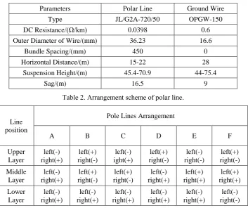
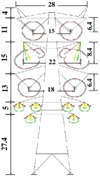
The pole conductors and grounding parameters to be adopted for the ±500kV three-circuit flexible DC transmission line project are shown in Table 1. The drum tower used is shown in Figure 1, and the typical pole conductor layout is shown in Table 2. The proportions of topography and soil resistivity along the Zhangbei ±500kV flexible DC grid demonstration project are shown in Tables 3 and 4.
Table 1. Parameters of ground wires and conductors.
Parameters Polar Line Ground Wire
Type JL/G2A-720/50 OPGW-150
DC Resistance/(Ω/km) 0.0398 0.6
Outer Diameter of Wire/(mm) 36.23 16.6
Bundle Spacing/(mm) 450 0
Horizontal Distance/(m) 15-22 28
Suspension Height/(m) 45.4-70.9 44-75.4
[image:2.595.122.476.457.753.2]Sag/(m) 16.5 9
Table 2. Arrangement scheme of polar line.
Line position
Pole Lines Arrangement
A B C D E F
2 8 1 5 2 2 1 8 4 11 15 13 5 27 .4 6. 4 8. 4 6. 4 22 18 15 28 27.4 13 15 11 4 5 6.4 8.4 6.4
[image:3.595.105.491.270.525.2]Figure 1. Parameters of typical tower (m).
Table 3. Terrain ratio of the line.
Terrain Length/km Ratio(%)
River Network 4.8 0.76
Flatland 138.4 21.87
Hills 142.6 22.54
Low Mountain 312.5 49.38
High Mountain 34.5 5.45
Table 4. Soil resistivity ratio of the line.
Soil Resistivity/(Ω·m) Power Frequency Grounding Resistance/Ω Length/km Ratio(%)
≤100 5(river network) 49.4 7.8
100~500 10(flatland) 123.5 19.52
500~1000 15(hills) 72.8 11.51
1000~2000 20(low mountain) 211.9 33.49
>2000 30(high mountain) 175.1 27.68
Analysis on the Lightning Protection Performance
Lightning Withstand Performance of Shielding Failure
[image:3.595.120.476.716.792.2]According to the above six pole conductor layout, the electrical trip-out rate of the ±500kV three-circuit flexible DC transmission lines arranged on the same tower and the influencing factors are analyzed by using the electrical geometric model. Table 5 and Figure 2 show the shielding failure trip-out rate under different thunderstorm intensities. During the calculation, the height of the tower is set as 75.4m, the protection angle is set as -10°, and the terrain is set as plain area. It can be concluded that the shielding failure trip-out rate of E and F layout is lower than that of the other four modes, among which F layout has the lowest shielding failure trip-out rate.
Table 5. Shielding failure trip-out rate under different thunderstorm days.
Thunderstorm Day /
(day/A)
Arrangement Scheme of Polar Line
A B C D E F
[image:4.595.199.395.225.340.2]
Figure 2. Shielding failure trip-out rate under different thunderstorm days.
Figure 3. Influence of tower heights on the shielding failure trip-out rate.
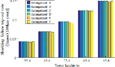
When the average value of the thunderstorm day is 40, the protection angle is -10°, and the terrain is a plain area, shielding failure trip-out rate at different tower heights is shown in figure 3. It can be seen that as the height of the tower increases, the trip-out rate of the six layout conductors increases. At the same height, the trip-out rate of the E and F layouts is lower than the other four modes.
In the plain area, as the height of the tower is 75.4 m and the thunderstorm day is 40, the trend of the shielding failure trip-out rate with the shielding angle is shown in Fig. 4. It can be seen that in the case of the negative protection angle, the trip-out rates of the four kinds of arrangements A, B, C, and D are basically equal, and the effect of protection angle is slight. On the contrary, the trip-out rate of the E and F layouts is reduced rapidly. When the protection angle is less than -10°, the E and F layouts have obvious advantages in the lightning protection performance. However, in high mountain areas, as shown in Fig. 5, the trip-out rates of the six layout methods all decreased with the decrease of the protection angle. The trip-out rates of the four kinds of layouts A, B, C and D were still basically the same, while the trip-out rates of the E and F layout methods were slightly higher than that of the four above.
[image:4.595.184.412.566.711.2]
Figure 5. Shielding failure trip-out rate under different protection angle in mountain area.
Lightning Withstand Performance of Back Striking
The operating experience proves that the flashback resulted from the lightning stroke on the center of overhead grounding line is extremely rare and can be ignored. Therefore, only the lightning striking on top of the tower is considered when calculating the back striking trip-out rate. Also it should be pointed out that this paper mainly considers the influence of grounding resistance on back striking.
[image:5.595.184.414.327.446.2]
Figure 6. Influence of grounding resistance on the back striking trip-out rate.
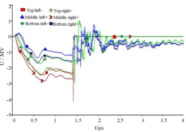
Figure 7. Voltage waveform when three-pole overhead transmission lines in flashover.
As the height of the tower is 75.4 m and the thunderstorm day is 40, the back striking trip-out rate for different grounding resistances is shown in Fig. 6. It can be seen that as the grounding resistance increases, the back striking trip-out rate increases significantly. Under the same grounding resistance, back striking trip-out trip rate of the six arrangements is basically the same, and the number of poles of flashover is also the same. Figure 7 shows the voltage waveform of the three-pole flashover when the grounding resistance is 5 Ω.
Discussion
[image:5.595.203.395.472.608.2]shielding failure is the lightning protection angle, while the more independent factor affecting the lightning back striking withstand level is the grounding resistance. If the pole wire adopts the E arrangement and the height of the tower is 75.4m, when the protection angle α≤-14°, the shielding failure trip-out rate can be kept at a small level whether in the mountain or the plain area. At the same time, if the grounding resistance value is reasonably set and the corresponding back striking trip-out rate is limited, the total lightning stroke trip-out rate of the line can be controlled to be 0.1 times/(100 km·a) or less.
Conclusions
In this paper, the lightning withstand performance of the ±500kV multi-terminal flexible DC transmission lines arranged on the same tower is studied. By adopting the electrical geometry model and the traveling wave method, the shielding failure and back striking trip-out rates of the three-circuit DC overhead lines on the same tower are calculated respectively. The effects of pole conductor layout, lightning shielding angle, topography and ground resistance on lightning protection performance of the DC lines are analyzed. Finally, the lightning protection scheme of ±500kV three-circuit DC overhead lines arranged on the same tower is recommended, which lays a foundation for the design and construction of the three flexible DC lines on the same tower.
References
[1] Yue Lingping, Lu Liping, Zhang Xuyong, et al. Assessment on Lightning Performance of ±500kV Overhead DC Power Transmission Line From Yichang to Shanghai[J]. Power System Technology, 2012, 36(7): 161-165.
[2] Zeng Rong, Zhou Xuan, He Jinliang. Review of Research Advances and Fronts on International Lightning and Protection[J]. High Voltage Engineering, 2015, 41(1): 1-13.
[3] Gu Dingxie, Zhou Peihong. Comparison and analysis of the UHV transmission line lightning shielding failure trip ratio calculated by LPM and EGM[J]. Electric Power, 2008, 41(8): 85-89.
[4] Sima Wenxia, Yang Qing. Analysis and Prospect of Lightning Shielding Failure Evaluation Methods of Transmission Lines[J]. High Voltage Engineering, 2015, 41(8): 2500-2513.
[5] Zeng Rong, HE Jinliang, Chen Shuiming. Lightning Protection Study of Transmission Line, Part II: Analysis Methods[J]. High Voltage Engineering, 2009, 35(12): 2910-2916.
[6] Li Zhijun, Chen Weijiang, Jiang Wendong. Research on Lightning Protection of Lattice Composite Material Tower of 110kV Double Circuit Line[J]. High Voltage Engineering, 2015, 41(1): 76-83.
[7] Peng Xiangyang, Li Zhen, Li Zhifeng. Influence of Tower Grounding Resistance on Lightning Protection Performance of Transmission Lines with Multi-circuits on the Same Tower[J]. High Voltage Engineering, 2011, 37(12): 3119-3119.
[8] Yang Qing, Sima Wenxia, Sun Yihao, et al. Lightning Protection Performance of Back-flashover for Quadruple-circuit Trans-mission Line with Dual Voltage 1000kV/500kV on the Same Tower[J]. High Voltage Engineering, 2012, 38(1): 132-139.
[9] Fan Mian, Wan Lei, Dai Min. Lightning Performance Simulation of Quadruple-circuit Transmission Line with Dual Voltage 1000kV/500kV on the Same Tower[J]. High Voltage Engineering, 2013, 39(3): 584-591.
[11] Tan Jin, Zhang Huanqing, Liu Yujun, et al. Analysis on Lightning Withstand Performance of the Sanhu ±500kV Double Circuit HVDC Power Transmission Line[J]. High Voltage Engineering, 2010, 36(9): 2173-2179.
[12] LI Jinliang, Du Zhiye, Ruan Jiangjun, et al. Lightning Performance of ±800kV and ±500kV Double-Circuit DC Transmission Line[J]. Electric Power Construction, 2014, 35(7): 74-79.
[13] He Junjia, Jiang Zhenglong, He Hengxin. Experimental Analysis on Lightning Shielding Performance and Protective Measures of DC Transmission Line[J]. High Voltage Engineering, 2011, 37(1): 21-26.
[14] He Jinliang. The Lightning Protection Characteristics of ±800kV Yunnan–Guangdong UHVDC Transmission Line[J]. Southern Power System Technology, 2013, 7(1): 21-27.
[15] Wang Jian, Wan Shuai, Chen Jiahong. Analysis of Lightning Protection with Line Surge Arrester for the Three Gorges-Shanghai ±500kV Double-circuit DC Transmission Line on the Same Tower[J]. High Voltage Engineering, 2013, 39(2): 450-456.