2017 2nd International Conference on Computer Engineering, Information Science and Internet Technology (CII 2017) ISBN: 978-1-60595-504-9
Design and Implementation of Carrier Aggregation
in LTE—An Air-Interface Analyzer
RUYING LI, ZHIZHONG ZHANG and XIANGTIAN DENG
ABSTRACT
Focusing on difficulties in communication networks test and optimization since some key technologies like carrier aggregation applied in communication networks, a LTE-An air-interface analyzer design scheme was proposed, which supports 3GPP R10/11 protocol standards and carrier aggregation. Firstly, the physical and logical architecture of LTE-A air-interface analyzer was introduced, and the relationship between them, the function of each module in them was illustrated. The application of the scheme can accelerate the commercialization of carrier aggregation in communication network, speed up the network deployment process and shorten the network construction cycle, and it will play an indispensable role in communication network operation and maintenance.
KEYWORDS
International Conference, International Conference, International Conference.
INTRODUCTION
Due to the flattening of the LTE network structure, the disappearance of the traditional signaling acquisition points, leads to the air-interface signaling should be collected from air-interface, also named Uu port[1], which increases the complexity of communication network management and optimization, what’s more, the traditional protocol analysis instrument is hard to meet LTE-A in the new technology and new business testing needs[2], the market urgently need a new type of network monitoring and optimization solutions.
Based on the design of LTE-A air-interface analyzer, this paper presents a realization scheme of carrier aggregation, and designs a user management scheme to ensure the service quality of multi-user.
OVERALL DESIGN OF LTE-A AIR-INTERFACE ANALYZER
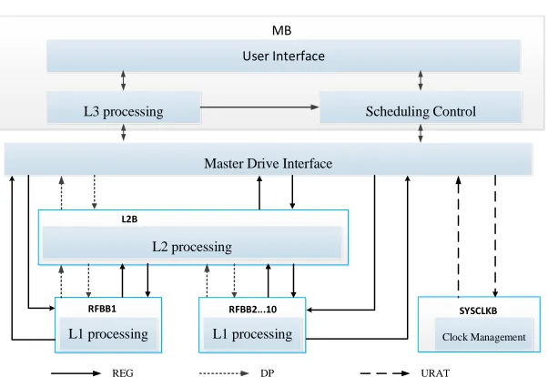
LTE-A air-interface analyzer can be divided into 4 parts by its physical architecture[3-4], including main control board (MB), RF base board (RFBB), layer two processing board (L2B) and the system clock board (SYSCLKB)[5]. As shown in Figure 1, the boards are interconnected by PCIE (Peripheral Component Interconnect Express, a high-speed serial bus standard), high-speed data communication can be realized via PCIE X1 or PCIE X2 bus.
_________________________________________
Figure 1. Physical architecture of LTE-A Air-interface Analyzer.
Figure 2. Overall design of LTE-A Air-interface Analyzer.
The board functions as follows:
1) RF base board includes RF board and baseband board, RF board is responsible for collecting RF data, the baseband board is responsible for RF acquisition of IQ in-phase orthogonal IQ data into bit stream data and encapsulated into frames.
2) Layer 2 processing board receive RF baseband data through the PCIE, and it is responsible for PDCP, MAC, RLC sub-layer protocol analysis and MAC data processing.
3) The main control board is responsible for the third layer and upper layer protocol analysis, recovery the L2B processing data into TCP/IP data packets, make real-time monitoring of user behavior.
4) The system clock board is responsible for providing a unified high-precision clock function for the instrument.
Correspondingly, as shown in Figure 2, according to the logic division, the analyzer includes L1 processing module, L2 processing module, master drive interface module, L3 processing module, scheduling control module, user interface module and clock management module.
L1 processing module, L2 processing module and the master drive interface
MB
L2B L3 processing
L2 processing
RFBB1
Master Drive Interface
User Interface
Scheduling Control
RFBB2...10
L1 processing
REG DP
SYSCLKB
Clock Management URAT
[image:2.612.149.450.187.394.2]DESIGN AND IMPLEMENTATION OF CARRIER AGGREGATION IN LTE-A AIR-INTERFACE ANALYZER
Carrier aggregation is introduced to improve the peak transfer speed of communication system, from the view of upper layer, carrier aggregation is to combine the resources of multiple cells together for the terminal [6]. When a terminal which supports carrier aggregation is in the idle state or the amount of data does not need to open the carrier aggregation module, its behavior is consistent with the no carrier aggregation terminal. When a terminal is in the idle state, its cell selection, resident, re-election and other operations still use cell as basic unit.
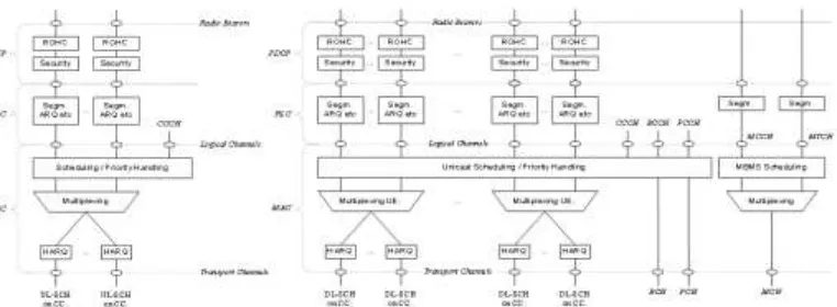
In the air-interface analyzer instrument, data aggregate in MAC layer. The L2 architecture is shown in Figure 3, to support carrier aggregation, the MAC layer allocates a separate HARQ entity for each member carrier, and the CA operates on the MAC Layer is complete and is not visible to PDCP and RLC layers [7].
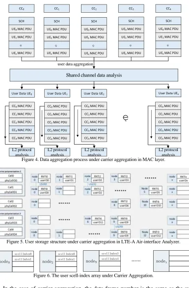
3GPP lists the five kinds of deployment scenarios for carrier aggregation. It must be pointed out that CA is a characteristic of UE. In R10, it is only applicable when multiple cells have overlapping coverage and belong to the same eNodeB. Since all the carriers under the same base station are in synchronization state, so that the sub-frame at the same time has the same system sub-frame number and sub-sub-frame number. The UE with the CA is configured to use the same cell radio network temporary identification C-RNTI in all the service cells. Therefore, in the monitoring instrument, carrier information and RNTI information can determine its carrier aggregation information. The determination of the carrier can be realized according to the physical channel ID, and the RNTI information is provided by the baseband board. The carrier aggregation module in the LTE-A air interface monitoring module is implemented in L2B. The main function is to carry out MAC layer aggregation on the data scanned and stored on the RFBBs. The independently sent MAC PDUs are aggregated into one stream. The aggregated data stream is sent to the RLC and PDCP sublayers for analysis. MAC layer aggregation data from the shared channel, the other channel data are independent, L2B CA operation includes four steps, as shown in Figure 4:
[image:3.612.107.488.495.635.2]1) User data aggregation process;
CC0
SCH
UE0 MAC PDU
UE1 MAC PDU
UEx MAC PDU
Shared channel data analysis
CC1
SCH
UE0 MAC PDU
UE1 MAC PDU
UEx MAC PDU
CC2
SCH
UE0 MAC PDU
UE1 MAC PDU
UEx MAC PDU
CC3
SCH
UE0 MAC PDU
UE1 MAC PDU
UEx MAC PDU
CC4
SCH
UE0 MAC PDU
UE1 MAC PDU
UEx MAC PDU
User Data UE0
CC0 MAC PDU
CC1 MAC PDU
CC2 MAC PDU
CC3 MAC PDU
CC4 MAC PDU
L2 protocol analysis
User Data UE1
CC0 MAC PDU
CC1 MAC PDU
CC2 MAC PDU
CC3 MAC PDU
CC4 MAC PDU
User Data UE2
CC0 MAC PDU
CC1 MAC PDU
CC2 MAC PDU
CC3 MAC PDU
CC4 MAC PDU
User Data UEx
CC0 MAC PDU
CC1 MAC PDU
CC2 MAC PDU
CC3 MAC PDU
CC4 MAC PDU
[image:4.612.107.492.46.633.2]L2 protocol analysis L2 protocol analysis L2 protocol analysis user data aggregation
Figure 4. Data aggregation process under carrier aggregation in MAC layer.
Figure 5. User storage structure under carrier aggregation in LTE-A Air-interface Analyzer.
node0 scellIndex0 scellIndex1 node9 scellIndex3 scellIndex4 nodex node2 scellIndex0 scellIndex1
Figure 6. The user scell-index array under Carrier Aggregation.
3) User data stored procedure;
After the data analysis process, the analyzer establishes a data index user for each user to cache the shared channel data for all carriers in the same sub frame.
4) L2 protocol analysis process.
After the data storage process, the analyzer will call the L2 parsing function to process the acquired MAC PDU data in indexed order, regardless of the processing order of the different carrier data.
Figure 5 shows the user storage structure under carrier aggregation in the LTE-A air-interface analyzer. The analyzer creates an array of user nodes for each cell in which the user C-RNTI is stored and its node number + 1 location stores the user ID. In all the cells monitored by the same instrument, the user ID is numbered consecutively from 0. The user in the carrier aggregation state configures the same user node in the aggregated cell, and the carrier aggregation data is merged by the user ID.
The subarea list of user IDs is saved through an auxiliary cell array. The sub-cell index array is an array of 5 members, each of which corresponds to the baseband cell, which stores the value of the sub-cell index (scell-index) in the carrier aggregation, which is deleted when the secondary cell is added and the secondary cell is released. For the user data in Figure 5, including the carrier aggregation information users have user0, user2 and user9, the corresponding sub-cell preservation array shown in Figure 6.
CARRIER AGGREGATION PROCESS IN LTE-A AIR-INTERFACE ANALYZER
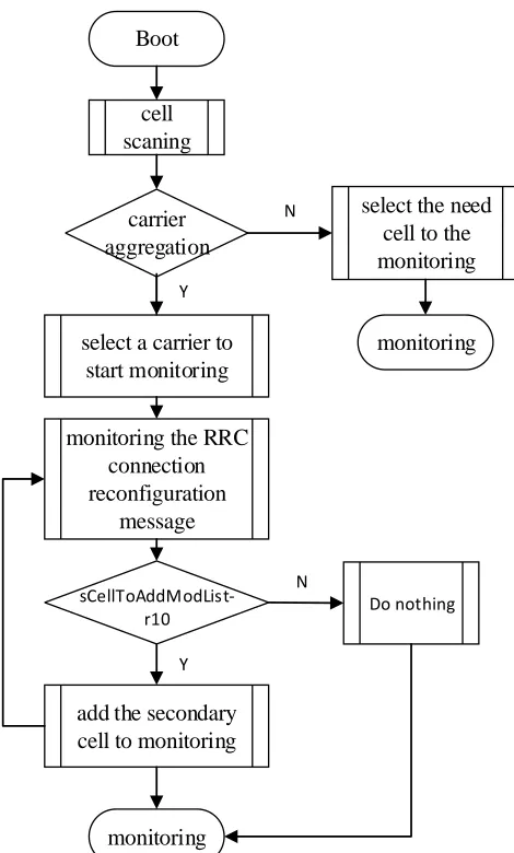
The monitoring process of the carrier aggregation in the monitor includes four steps, as shown in Fig. 7:
(1) Boot the instrument, select whether open carrier aggregation function module in test, began to cell scan;
(2) When open carrier aggregation function module, select a carrier to start monitoring, otherwise, select the need cell to the monitoring;
(3) Monitoring the RRC connection reconfiguration message, add the secondary cell when detect the secondary cell adding message;
Boot
cell scaning
carrier aggregation
Y
select a carrier to start monitoring
N select the need
cell to the monitoring
monitoring
monitoring the RRC connection reconfiguration
message
sCellToAddModList-r10
Y
add the secondary cell to monitoring
N
monitoring
[image:6.612.189.424.52.442.2]Do nothing
Figure 7. Carrier aggregation monitoring process.
SUMMARY
REFERENCES
1. Wang Yingming, Sun Shaohui. TD-LTE Principles and System Design [M]. Beijing: Posts &Telecom Press, 2010:431
2. Hua Yan. Discussion on TD - LTE Key Technology and Development Trend [J]. China New Technologies And Products.2011,(15):3
3. Ministry of Science and Technology of the People’s Republic of China. 2013 annual report guidance of new generation broadband wireless mobile communications network National Science and Technology Major Project.
4. Peng Yu, Jiang Honglan, Yang Zhiming, Qiao Liyan, Liu Wang. Design of general digital signal process based on DSP and FPGA [J]. Foreign Electronic Measurement Technology. 2013, 32(01):17-21.
5. Li Caiqi, Zhang Zhizhong, Cheng Fang. RLC Protocol Monitoring Technology in LTE-A Air Interface Instrument [J], Video Engineering, 2015, 39(17):58-62.
6. Ji Gang. The LTE CA commercial practice and research [A]. Tianjin TV Technology Research Association. Tianjin TV Technology Research Association 2016 Annual Conference Proceed [C]. Tianjin TV Technology Research Association. 2016: 5.