Hybrid modelling and simulation of a computer
numerical control machine tool feed drive
C Pislaru*, D G FordandG Holroyd
Ultra Precision Engineering Centre, University of Huddersfield, UK
Abstract: The paper presents a new approach to the modelling and simulation of a computer numeri-cal control (CNC ) machine tool feed drive. The hybrid model of the drive incorporates a distributed load, explicit damping factors and measured non-linear effects in order to achieve a realistic dynamic performance. In this way, the shortcomings of traditional modelling methods applied to CNC machine tool axis drives are overcome. A MATLAB/SIMULINK package was used to simulate this new model for a CNC machine tool feed drive. A novel hybrid model with a distributed load, explicit damping factors, backlash and friction was developed and shown to have a similar dynamic response to the machine tool feed drive system under the same conditions. The simulated results display resonance frequencies, while the lumped-parameter models generate only the response of a second-order element.
Keywords: machine tools, feed drives, motion control, hybrid modelling, simulation, dynamic systems, frequency domain
NOTATION
A scaling term to simulate the
potentiometer setting to control the preamplifier input demand
c
hm coefficient of viscous damping
(N m s/rad )
E
1 position error (mm)
E
2 rate loop error ( V )
E
3 current loop error ( V )
E
4 voltage input to the motor windings ( V ) F
n normal force (N )
F
s applied force (N )
F∞
b interim feedback force (N )
G
1 digital-to-analogue conversion scaling
term (mA/mm)
G
2 digital-to-analogue conversion scaling
term ( V/mA)
G
3 scaling term
G
4 preamplifier forward path scaling ( V/A) I
a armature current of the d.c. motor (A)
J moment of inertia (kg m2)
k
h torsional stiffness (N m/rad )
K preamplifier gain
The MS was received on 3 December 2002 and was accepted after revision for publication on 12 September 2003.
* Corresponding author: Ultra Precision Engineering Centre, School of Engineering, University of Huddersfield, Queensgate, Huddersfield HD1 3DH, UK.
K
br bridge voltage scaling ( V/V ) K
e d.c. motor voltage constant ( V s/rad ) K
i integral gain
K
ia current loop scaling term ( V/V ) K
p proportional gain
K
nut axial stiffness of the nut (N/m) K
t motor torque time constant (s)
K
ta tachometer constant ( V s/rad ) L
a motor armature inductance (H )
m
load load moving mass (kg)
R motor armature resistance (V)
s Laplace operator
T generic mechanical torque (N m)
T
bear reaction torque generated by the motor
bearings (N m)
T
Coulomb reaction torque due to Coulomb friction
(N m)
T
g d.c. motor electrical torque (N m)
T
mot reaction torque generated by the motor
shaft (N m)
v velocity (m/s)
v
e velocity tolerance
v
edef default velocity tolerance
|v| velocity norm
V
1 controller output ( V )
V
2 preamplifier output ( V )
V
3 power amplifier output ( V )
V
4 armature current loop feedback ( V )
V
V
6 rate feedback provided by the tachometer
( V )
V
7 linear encoder feedback (mm)
X
1 model input (rate demand ) (m/s)
b relative angular acceleration (rad/s2)
b
1 d.c. motor angular acceleration (rad/s2)
h relative angular displacement (rad )
m coefficient of friction
m
1 friction ratio
t controller sampling time (ms)
t
1,t2,t3 preamplifier time constants (ms)
v relative angular velocity (rad/s)
v
1 d.c. motor angular velocity (rad/s)
1 INTRODUCTION
Traditional methods for modelling and simulation of computer numerical control (CNC ) machine tool feed drives have used lumped-parameter models with load inertia reflected to the motor [1–3]. These models presented significant shortcomings:
1. The lumping of any system removes the effect of model components, with a corresponding reduction in simulation accuracy.
2. Changes in any system component require the alteration of the entire lumped model.
3. It is not possible to examine the behaviour of individual components and how they interact.
To overcome these shortcomings, a modular approach has been applied to the modelling of CNC machine tool feed drives [4–7]. The feed drive elements were defined as modules, and the torque generated by a d.c. motor had to overcome mainly the frictional forces in the slide guides, the bearing friction, the frictional losses in the ball-screw nut and the load element inertia. These were still lumped-parameter models with load element per-formance in the time domain expressed as differential equations.
The modular approach was similar to the Newton– Euler model [8] for a robot, where kinematic motion was transmitted forwards through the model and resistive force used as feedback. In previous studies [4–7] it has been supposed that this technique allows the inclusion of combined resonant states of individual elements without requiring exact constituent damping factors.
However, the dynamic performance for single-axis simulation using lumped-parameter models with a modular load was considered not to be sufficiently realistic when compared with the machine measured data [9]. Therefore, a hybrid model of a CNC machine tool feed drive with distributed load, explicit damping coefficients, backlash and friction was developed. Effectively, the damping coefficients for Coulomb and
I08502 © IMechE 2004 Proc. Instn Mech. Engrs Vol. 218 Part I: J. Systems and Control Engineering
viscous friction were introduced into the individual elements of the models presented in references [4] to [7]. The hybrid model was built on the considerations expressed by Bartlett and Whalley [10,11]. A mixture of ordinary differential equations and partial differential equations could describe this combination of distributed and lumped elements. The ball-screw was modelled with distributed parameters, while the models of other mechanical components (bearings, belt and pulleys, etc.) contained lumped parameters. Regarding non-linearities included in the model, friction could still be defined by a differential equation, but backlash was described by a partial differential equation as a result of being a function of two variables (time, space).
The hybrid model of a CNC machine tool feed drive was implemented in SIMULINK 5. This recent version of the simulation package presents new enhancements regarding blocks, simulation and models, and of course its accelerator, which enabled the hybrid model to run in a short period of time.
The simulation results of the hybrid model with swept sine stimuli signals compared favourably with the measured response at the machine. Therefore, the hybrid model with distributed load, explicit damping coefficients, backlash and friction represented to a large extent the dynamic behaviour of the axis drive selected. This model produced data useful for the prediction of performance, accuracy, stability and safety issues associated with the drive system.
2 MODELLING CONSIDERATIONS
The model of a CNC machine tool axis drive has three major parts:
1. TheCNC controller blockcalculates the axis motion necessary to execute the required cutting path. 2. Theaxis actuator includes the electrical motor,
pre-amplifier, current control loop, power amplifier and transducers (tachogenerators, encoders).
3. Themechanical system typically contains the follow-ing: coupling between drive and screw, ball-screw, nut unit, slides, slideways and associated bearings.
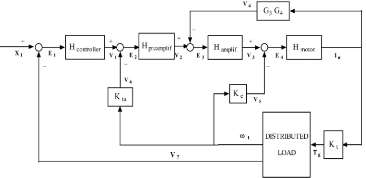
The block diagram of the hybrid model for a single-axis drive of the Beaver VC35 CNC machine tool (in use at the University of Huddersfield ) is presented in Fig. 1. It describes the operation of the Y axis position servo
system which moves the saddle with worktable
attached above.
Consideration of the transfer function for the FANUC 6M controller integrated in the actual machine yields
H
controller= G
1G2A
s ×
1−e−st
st (1)
Fig. 1 Block diagram of the hybrid model for the horizontal axis of CNC machine tool conversion and the transmission of position error at fixed
time intervals. The controller sampling time generates the quantization effect which is simulated by a zero-order hold block from the SIMULINK library.
The preamplifier is a PI element with transfer function
H
preamplif=Kp+ K
i
s (2)
The power amplifier is considered to be a four-quadrant transistor bridge. The relationship between output and input is represented by a scaling factor
H
amplif=KbrKia (3)
The electrical part of the d.c. motor is represented by
H motor=
1
sL a+R
(4)
The mechanical time constant of the d.c. motor is included in the distributed load model. The following factors involved in energy dissipative processes are con-sidered when predicting the drive dynamic behaviour:
(a) resistance in the motor bearings and seals, (b) damping in the motor shaft,
(c) friction and damping in the drive belt, (d ) resistance in the ball-screw bearings and seals, (e) damping in the ball-screw (both torsional and
axial ),
(f ) friction and damping between the ball-screw and its nut,
(g) friction between table and saddle (X drive) or between saddle and bed (Ydrive).
The backlash between ball-screw and its nut is also taken into account.
There are five main inertia elements in the drive: motor,J
m, driving pulley, Jp1, driven pulley, Jp2,
ball-screw, J
BS, and ball-screw load, Jload. Also, there are
three main stiffness elements: motor shaft,K
1, belt drive, K
2, and ball-screw, KBS. Only the static stiffness of the
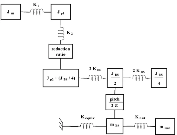
system elements is examined in this investigation. The schematic diagram of the mechanical transmission system components treated as one-mass oscillators is displayed in Fig. 2.
The motor, pulleys and load are described as single lumped inertia elements, and the ball-screw is divided into seven modules with the ball-screw flexibility apportioned between each. The load is assumed to be in a central position along the ball-screw length.
The equivalent stiffness, K
equiv, for the system
ball-screw bearings is determined considering that the stiff -ness of one type of bearing in series with one half of the screw is connected in parallel with the stiffness of the other type of bearing in series with the other half of the screw. In the case of a ball-screw supported by bear-ings on each end (the analysed case), the static flexibility is highest when the nut is positioned at the ball-screw centre because the springs corresponding to each half of the total length are connected in parallel.
The mechanical elements are modelled considering the subsequent categories:
1. Inertia elements. The angular acceleration of a torsional element is calculated with the relation
b=T
J (5)
2. Spring/damper elements. In this investigation, the elements representing shafts are considered as a spring in parallel with a viscous damper. The torque equation considering rotating bodies yields
T=khh+chv (6)
3. Rotational damper.This is used to model that part of the bearing resistance that is proportional to shaft speed. The element is basically a spring/damper without the spring, and the torque generated is
T=c
hv (7)
[image:3.595.121.477.60.233.2]Fig. 2 Schematic diagram of the mechanical transmission system components
used to model that part of the bearing resistance that opposes motion with a constant torque, provided the shaft is moving. The maximum torque, T
max,
nor-mally transmitted by the shaft is used instead of the normal contact force, and a ‘friction ratio’,m
1, is used
instead of the coefficient of friction. The torque,T bear,
absorbed when the bearing is subjected to torqueT
is
T
bear=T whenT∏m1×Tmax (8) T
bear=m1Tmax whenT>m1×Tmax (9)
In representation of the CNC machine tool dynamics, the various parts of the drive are modelled as follows:
1. The d.c. motor. As an inertia element and rotational damper element it represents that part of the bearing resistance that is proportional to shaft speed. The angular acceleration of the d.c. motor, considered as an inertia element, is calculated by the relation:
b 1=
T
g−Tmot−Tbear J
m
=Tg−Tmot−(TCoulomb+T) J
m
(10)
The reaction torque from the motor bearings,
T
Coulomb, that is due to linear (Coulomb) friction is
up to 2 per cent of the motor nominal torque in this case. More details about the implementation of the Coulomb friction phenomenon in SIMULINK are discussed in the next section.
2. The belt drive. The pulleys are represented as inertia elements and a rotational frictional element is also introduced in the case of the driven pulley. Also, the Coulomb friction that arises from the pulley and belt teeth is considered. The longitudinal vibrations resulting from the belt being an elastic link between
I08502 © IMechE 2004 Proc. Instn Mech. Engrs Vol. 218 Part I: J. Systems and Control Engineering
two rotating masses (driving and driven pulleys) with given moments of inertia are modelled. Transverse vibrations are not considered because it is assumed that there is no imbalance of belt or pulleys that could be caused by dimensional variations, improper mounting, etc. The dynamic behaviour of the belt material is modelled as a spring/damper type element. However, it is possible for the belt to go slack on one side when the belt is tensioned and sufficient torque is applied. In this case, only half the belt will be in play, and this is a non-linear situation.
3. The ball-screw. This is represented by seven modules as shown in Fig. 3. The torsional flexibility of the ball-screw contained in the ‘BS1’ and ‘BS2’ modules is depicted by two torsional spring/damper elements. The axial stiffness of the ball-screw and its mounting
[image:4.595.151.444.55.279.2] [image:4.595.310.548.530.720.2]bearings from the ‘BS axial stiff’ module is modelled by a linear spring/damper element. The dynamic behaviour of the ball-screw middle is represented by a special element, ‘BS middle’, that performs several functions:
(a) It acts as an inertia element that calculates torsional movement of the ball-screw middle (the portion nearest to the nut).
(b) The torsional rotation of the ball-screw is con-verted into linear movement of the nut using a factor equal to the screw pitch divided by 2p. (c) It acts as an inertia element for the linear
move-ment (axial behaviour) of the ball-screw middle that is caused by the reaction force from the nut acting on the ball-screw and its support bearings. (d ) The total axial movement of the ball-screw part
acting on the nut is calculated.
The dynamic behaviour of the ball-screw nut is also represented by a special element, ‘BS nut’, that performs several functions:
(a) It acts as a spring/damper element connecting the ball-screw middle to the saddle.
(b) The backlash is taken into consideration. (c) The ball-screw could act in a ‘positive’ mode
(the screw drives the nut) or in a ‘negative’ mode (the nut drives the screw).
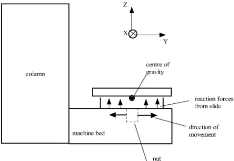
The dynamic behaviour of the ball-screw end, ‘BS end’, is modelled by an inertia element and a rotational frictional element. At this stage, the ball-screw sag under its own weight is not considered. From the measurements performed with acceler-ometers [9] it is obvious that the first resonance fre-quency is 35 Hz (219.8 rad/s). The cause of this resonance is assumed to be the rocking of the saddle and worktable around theXaxis (bottom axis). This conclusion results from observing the behaviour of the actual machine when the input signal is a sine wave of 35 Hz frequency. When the worktable and saddle move in the Y axis direction, the reaction forces from the slides produce tilting of the worktable and saddle around theXaxis. Also, a torque is pro-duced around the X axis because the movement of the saddle and worktable is in the Y axis direction. A graphical description of this phenomenon is por-trayed in Fig. 4. The rocking around theXaxis can be represented as a torsional spring/damper element and is introduced into the ‘Bed stiffness’ block. 4. The saddle. This consists of a Coulomb ( linear)
friction element and an inertia element.
The model coefficients are calculated from the exper-imental data presented in reference [9] using a gen-eralized eigenvalue method. The model is validated by comparing the simulated results with measured data and by checking that the law of energy conservation (the sum of kinetic energy and potential energy remains constant) is obeyed.
Fig. 4 Worktable and saddle tilting aroundXaxis when the movement is in theYaxis direction
3 IMPLEMENTATION OF NON-LINEAR
ELEMENTS IN SIMULINK
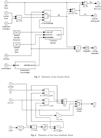
The ‘Friction’ block in Fig. 5 represents the implemen-tation of the Coulomb friction model. Problems were experienced with bringing a mass to rest during the development of the friction element. SIMULINK solves the equations in a sequence of steps separated in time. When a mass is moving only slowly in the positive direc-tion, a reaction force due to Coulomb friction (m×F
n)
is acting. If this force is sufficient to cause the mass to stop and start moving backwards in the cycle time of the solution process, the force (m×F
n) reverses and
starts to push the mass forwards again. This can cause the force to change signs again, and so on, generating a series of force ‘spikes’ in the process. Although the net effect is to keep the mass velocity close to zero, it was considered that the force spikes are not desirable. The following steps were followed to avoid this problem:
1. An interim feedback force, F∞
b, was defined in two
particular cases:
If
K
vv e
K
<1 thenF∞
b=−Fs
A
v v eB
2
+m×F n
v
ve+Fs (11)
If
K
vv e
K
1 thenF∞
b=m×Fn v
|v| (12)
The ‘Variable limiter’ block is similar to the ‘Saturation’ block from the SIMULINK library, but the upper and lower limits are estimated by the model rather being predefined.
[image:5.595.308.547.58.223.2]Fig. 5 Elements of the friction block
Fig. 6 Elements of the force feedback block this block:
Ifv
e<vedef thenve=vedef (13)
Ifv
e∏vedef thenve=3.13×|a×dt| (14)
The default value for velocity tolerance is v edef=
0.0005 and the solver cycle time is dt=1 ms. The value 3.13 for zero trap width is chosen using a trial and error method.
I08502 © IMechE 2004 Proc. Instn Mech. Engrs Vol. 218 Part I: J. Systems and Control Engineering
The ‘Acceleration loop breaker’ block (Fig. 5) has the role of avoiding problems with arithmetic loops from the ‘Friction’ subsystem. The current calculated value for acceleration,a
estimat(i), is replaced by one estimated
from the previous two values [a(i−1),a(i−2)]:
a
estimat(i)=2×a(i−1)−a(i−2) (15)
[image:6.595.81.500.58.630.2]toler-Fig. 7 Elements of the variable limiter block ance band which defines the smooth curves applied to
calculate the forces used to bring a part of the model to rest. The details for modelling the behaviour of other non-linear elements of the mechanical transmission are discussed in reference [9].
4 MEASUREMENT TECHNIQUE
The initial idea for determining the Bode diagrams of one axis was to introduce sinusoidal inputs into the con-troller and to measure the concon-troller output. However,
Fig. 8 Elements of the tolerance adjuster block
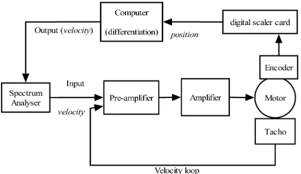
Fig. 9 Experimental set-up for measurements in open-loop position control and closed-loop velocity control
this was not possible because of the lack of technical data for the controller installed on the analysed machine. The alternative was to introduce a sinusoidal signal generated by a spectrum analyser as a disturbance into the preamplifier. The signal amplitude was limited to 250 mV because the mechanical transmission has a maxi-mum acceleration limit of 0.5 g. The voltage of 250 mV produced a table movement greater than 1mm. The fre-quency maximum value that could be measured in this way was 50 Hz, dictated by Shannon’s law and the sampling time of the existing controller (10 ms).
To measure frequencies above 50 Hz, it was necessary to ‘open’ the position loop (the controller was not con-trolling the position loop any longer) (see Fig. 9). In this way it was possible to introduce an input signal of greater amplitude (1 V ), capable of generating enough energy to make the output signal greater than the noise level and move the worktable distances greater than 1mm.
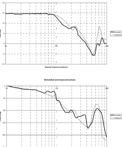
[image:7.595.119.480.62.193.2] [image:7.595.48.285.370.516.2] [image:7.595.150.444.549.719.2]Fig. 10 Simulated and experimental Bode diagrams general data logging software developed at University
of Huddersfield [9]. The resulting digital signal is transformed into a voltage by a D/A card, and then the analogue signal is introduced into the spectrum analyser.
5 COMPARISON BETWEEN SIMULATED
RESULTS AND MEASURED DATA
The SIMULINK model corresponding to the exper-imental set-up depicted above is built and the simulated
I08502 © IMechE 2004 Proc. Instn Mech. Engrs Vol. 218 Part I: J. Systems and Control Engineering
results are plotted on the same graphs in Fig. 10. The resonance frequencies displayed on the experimental Bode diagrams are transmitted from mechanical load through belt and pulleys to the motor.
The existing differences between simulated and measured results could be due to various factors:
1. A trial and error method has been used in simulation, and therefore it is possible that the model coefficients do not have the best optimum value.
factors for other joints that are influencing the dynamics of the system.
3. The effect of magnetic coupling between tacho-generator and d.c. motor at high speed [12] and other phenomena need to be included in the model after further research has been performed.
4. Other non-linear effects and the drive behaviour at high speed need to be studied and incorporated in the model.
6 CONCLUSIONS
This paper shows that the hybrid model with distributed load and explicit damping factors represents to a large extent the drive dynamic behaviour of the actual machine. This fact is proven by the comparison of single-axis simulation results for a swept sine signal introduced directly into the preamplifier of the CNC machine tool feed drive, with the measurements taken for the same conditions at the machine.
The feed drive system is modelled element by element, including for all known non-linear factors (stiffness, fric-tion, and backlash) as identified by measurement using specialized equipment. The efficiency of modelling the ball-screw as distributed mass/inertia and stiffness is proven by the simulation results.
The particular emphasis in this paper is placed on modelling the non-linear behaviour of the belt mission and ball-screw. These two mechanical trans-mission components play an important role in the dynamics of the CNC machine tool.
The presented method contributes to knowledge of modelled and simulated motion control systems for CNC machine tools. Modules have been created for different parts of the CNC machine tool feed drive. This allows greater flexibility in the model construction and an investigation of the interaction between model com-ponents. In this way, the shortcomings of traditional methods are overcome.
In addition, the modular approach permits the calcu-lation of forces that occur between model components. The lumped-parameter model does not offer this oppor-tunity, which is detrimental to design practice. Knowing the values and causes of different forces will be useful for designers in determining the modalities for error avoidance.
Accurate load models will also assist the end-user by allowing diagnostic and condition monitoring methods to be applied to CNC machine tools. The main interest for the end-user is the workpiece accuracy and the knowledge of what influence the feed drive elements have on machine errors.
More research is necessary in order to determine the relationship between the model coefficients and system response. In this way, the simulated results will provide
a better match to the experimental results for the same conditions.
For the moment, the method has been applied only to a machine with an analogue drive. In the future, the modular approach will be used in studying CNC machine tools with linear transducers and digital drives.
ACKNOWLEDGEMENTS
The authors would like to acknowledge the financial support of the EPSRC. The main part of the work was carried out under EPSRC Grant GR/R35186/01 for reduction of errors in the design and integrated manufac-ture of CNC machine tools.
REFERENCES
1 Ford, D. G. General purpose CAD/CAE aid to design a machine tool system. PhD thesis, University of Huddersfield, 1987.
2 Gross, H.Design versions of the mechanical transmission elements. InElectrical Feed Drives for Machine Tools, 1983 (John Wiley, Chichester).
3 Leonhard, W.Dynamics of a mechanical drive. InControl of Electrical Drives, 1997 (Springer-Verlag, Berlin and Heidelberg, Germany).
4 Pislaru, C., Ford, D. G. and Freeman, J. M. A new 3D model for evaluating the performance of CNC machine tool axis drives. In Proceedings of the 1999 International Conference of European Society for Precision Engineering and Nanotechnology, Bremen, Germany, June 1999, pp. 72–75 (Shaker Verlag, Germany).
5 Pislaru, C., Ford, D. G.andFreeman J. M.Dynamic simu-lation of CNC machine tool axis drives. In Proceedings of the 1999 International Conference onPower Conversion and Intelligent Motion, Intelligent Motion Section, Nuremberg, Germany, June 1999, pp. 259–264 (ZM Communication Gmbh, Germany).
6 Pislaru, C., Ford, D. G.andFreeman, J. M.A new approach to the modelling and simulation of a CNC machine tool axis drive. In Proceedings of the 1999 International Conference onLaser Metrology and Machine Performance, Newcastle upon Tyne, July 1999, pp. 335–343 ( WIT Press).
7 Pislaru, C., Ford, D. G. and Freeman, J. M. Improving CNC machine tools performance by using modular approach. In Proceedings of the 2001 International Conference onLaser Metrology and Machine Performance, Birmingham, July 2001, pp. 301–313 ( WIT Press).
8 Fu, K. S., Gonzalez, R. S. andLee, C. S. G. Robotics— Control, Sensing, Vision and Intelligence, 1988 (McGraw-Hill International, New York).
9 Pislaru, C.Parameter identification and hybrid mathemat-ical modelling techniques applied to non-linear control sys-tems. PhD thesis, The University of Huddersfield, 2001.
systems. Proc. Instn Mech. Engrs, Part C: J. Mechanical Engineering Science, 1988,202(C6), 421–429.
11 Bartlett, H.andWhalley, R.Analogue solution to the mod-elling and simulation of distributed–lumped parameter sys-tems. Proc. Instn Mech. Engrs, Part I: J. Systems and Control Engineering, 1998,212(I2), 99–114.
I08502 © IMechE 2004 Proc. Instn Mech. Engrs Vol. 218 Part I: J. Systems and Control Engineering