The on-line detection of engine mis re at low speed
using multiple feature fusion with fuzzy pattern
recognition
S Liu1*, F Gu2andA Ball2
1School of Mechanical Science and Engineering, Huazhong University of Science and Technology, Wuhan, People’s Republic of China
2Maintenance Engineering Research Group, School of Engineering, University of Manchester, Manchester, UK
Abstract: This paper proposes a technique for the on-line detection of incipient engine mis re based on multiple feature fusion and fuzzy pattern recognition. The technique requires the measurement of instantaneous angular velocity signals. By processing the engine dynamics model equation in the angular frequency domain, four dimensionless features for mis re detection are de ned, along with fast feature-extracting algorithms. By directly analysing the waveforms of the angular velocity and the angular acceleration, six other dimensionless features are extracted. Via fuzzy pattern recognition, all the features are associated together as a fuzzy vector. This vector identi es whether the engine is healthy or faulty and then locates the position of a mis ring cylinder or cylinders if necessary. The experimental work conducted on a production engine operating at low speeds con rms that such a technique is able to work with the redundant and complementary information of all the features and that it leads to improved diagnostic reliability. It is fully expected that this technique will be simple to implement and will provide a useful practical tool for the on-line monitoring and real-time diagnosis of engine mis re in individual cylinders.
Keywords: internal combustion engine, condition monitoring, fault diagnosis, fuzzy pattern recognition, data fusion, mis re, angular velocity
I(Fn) acceleration uctuation index ofnth
NOTATION
cylinder
I(Hn) maximum acceleration index ofnth am,bm mth element of AandB
cylinder A¯(n) estimate of angular acceleration
I(Ln) minimum acceleration index ofnth uctuation of nth cylinder
cylinder A,B fuzzy vector
I(Sn) summed acceleration index of nth cm,dm constant
cylinder DFT discrete Fourier transform
I(Tn) torque uctuation index ofnth cylinder h(õ) impulse response function of engine
I(Vn) velocity variation index of nth cylinder dynamics model
J moment of inertia
H(ì) Fourier transform ofh(õ)
K number of frequency harmonics utilized
i = 1
L number of data samples per engine cycle I(An) acceleration variation index ofnth
M dimension ofAandB
cylinder
n cylinder number
I(Cn) angular variation index ofnth cylinder
N number of cylinders
RF acceleration component ratio RT torque component ratio The MS was received on 29 June 2001 and was accepted after revision RT,0 threshold forRT
for publication on 30 January 2002. t time
* Corresponding author: School of Mechanical Science and Engineering,
Te(õ) rotating inertia torque Huazhong University of Science and Technology, Wuhan, Hubei,
TL(õ) total resistive torque 1 INTRODUCTION TL(ì) Fourier transform ofTL(õ)
Tp(mìc) DFT ofTp(õ) at mìc, for Tp(õ) within Considerable interest has been shown in the detection of one engine cycle incipient engine mis re in recent years. As exhaust emis-T(pn)(mìf) DFT ofTp(õ) at mìf, forTp(õ) ofnth sion control regulations become increasingly stringent, cylinder within one engine cycle it becomes even more likely that, if possible, mis re will Tp(õ) gas pressure torque be monitored continuously by the on-board diagnostic Tp(ì) Fourier transform ofTp(õ) system. To avoid costly engine failures and to reduce T¯(pn) estimate of gas pressure torque output of repair time, the diagnostic system should also be capable
nth cylinder of indicating the fault location, i.e. identifying the
Tr(õ) reciprocating inertia torque mis ring cylinder or cylinders in an early stage. Tr(ì) Fourier transform ofTr(õ) Mis re in internal combustion engines refers to a
situ-um mth element of U ation where the fuel–air mixture cannot be eYciently
U real vector combusted in one or more cylinders. Although direct
x(õ) =[ö(õ)]2 measurement of in-cylinder pressure of each individual
X(mìc) DFT ofx(õ) atmìc, for x(õ) within one cylinder may be the most precise approach for mis re engine cycle detection, it is obviously impractical because it requires X(n)(mìf) DFT ofx(õ) atmìf, forx(õ) of nth installing a costly pressure transducer in each cylinder. cylinder within one engine cycle However, the instantaneous angular velocity can be X(ì) Fourier transform ofx(õ) obtained easily and reliably, and this kind of signal may be widely utilized for engine monitoring, diagnosis and á(õ) crankshaft angular acceleration
control [1–4]. á(maxn) peak value of angular acceleration ofnth
The detection of engine mis re by instantaneous
angu-cylinder lar velocity measurement can be performed in two ways.
á(minn) valley value of angular acceleration of
The rst is based on waveform analysis, in which the nth cylinder
instantaneous velocity waveform is analysed directly and á(sumn) summed absolute value of angular
the extracted feature used to identify whether mis re acceleration of nth cylinder
exists in the engine by simple threshold or by more com-å minor positive value quite near zero
plicated Bayesian decision theory [5–7]. The second is õ crankshaft angular position
based on torque estimation, in which the instantaneous õ(maxn) crankshaft angular position
gas pressure torque (indicated torque) or individual cyl-corresponding to ö(maxn)
inder pressure is calculated by an engine dynamics õ(minn) crankshaft angular position
model, and from this the mis ring cylinder is identi ed corresponding to ö(minn)
[8–17]. ¢õ(n) crankshaft angular duration
At present, almost all mis re detection techniques are corresponding to ¢ö(n)
based only on a single feature or indicator. Each tech-[¢õ](n) crankshaft angular interval
nique has its own advantages and drawbacks with the corresponding to nth cylinder
result that no single technique has proven to be com-ì angular frequency variable
pletely reliable over a range of operating conditions. An ìc engine cycle frequency
important consideration is that under complex con-ìf engine ring frequency
ditions (such as when mis re happens simultaneously in í fuzzi cation member function
multiple cylinders) the information required to make ó degree of closeness between two fuzzy
reliable mis re decisions may simply not be available vectors
in a single feature. The diagnostic conclusions drawn ó1 maximum–minimum degree of closeness
by diVerent single features do not always concur and ó2 Euclidean distance degree of closeness
sometimes directly con ict [7,16]. ó0 threshold foró1(or ó2)
In recent years, multisensor data fusion has received ö(õ) crankshaft angular velocity
signi cant attention for automated target recognition, ö
k öengine cycle(õ) sampled at point kwithin one guidance for autonomous vehicles, remote sensing, battle- eld surveillance, monitoring of manufacturing ö(n)
k öwithin one engine cycle(õ) sampled at point kof nth cylinder process, condition-based maintenance of complex machinery, robotics and medical applications [18–20]. ö(maxn) peak value of angular velocity ofnth
Data fusion techniques combine data from diVerent sen-cylinder
sors with related information from an associated data-ö(minn) value of angular velocity of nth
base to achieve improved accuracy and more speci c cylinder
of sensitivity in one sensor domain can be oVset by infor- acceleration is actually an inverse problem, which can be solved more easily by transforming equation (1) from mation from other sensors, enabling, in theory,
success-ful decision-making ability over a wider range of the angular time domain to the angular frequency domain:
operating conditions.
In this paper, a technique for the on-line detection of
Tp(ì)=Te(ì)+Tr(ì)+TL(ì) engine mis re, which employs information from multiple
features, is proposed. The remainder of the paper is =1
2iìX(ì)[H(ì)]Õ 1+Tr(ì)+TL(ì) (2) organized as follows. In section 2, 10 dimensionless
fea-whereìis the variable in the angular frequency domain tures for mis re detection are introduced, along with fast
corresponding to the variableõin the crankshaft angular extraction algorithms. In section 3, the architecture for
domain, Tp(ì), Te(ì), Tr(ì) and TL(ì) are the Fourier the on-line mis re detection by multiple feature fusion
transforms of Tp(õ), Te(õ), Tr(õ) and TL(õ) respect-is presented. The multiple feature fusion procedure respect-is
ively,H(ì) is the Fourier transform ofh(õ) acting as the described in section 4. In section 5, the technique is
dem-transfer function of the system, X(ì) is the Fourier onstrated on experimental data from a four-cylinder
transform of x(õ)=[ö(õ)]2 and i= 1. Note that four-stroke diesel engine. This study is concluded in
the equality Te(ì)=12iìX(ì)[H(ì)]Õ 1 is obtained from section 6.
the diVerentiation property of Fourier transform, i.e. the Fourier transform of dx(õ)/dõis iìX(ì), and the relation-ship between angular acceleration and angular velocity
2 DIMENSIONLESS FEATURES AND
in theõdomain:
EXTRACTION ALGORITHMS
á(õ)=á(t)=dödt(t)=död[õt(t)]=dödõ(õ)dõd(tt)
2.1 Engine dynamics model and gas pressure torque estimation
=död(õõ)ö(õ)=12 d[öd(õõ)]2=12dxd(õõ) (3) If it is assumed that the engine is operating in a steady
state condition and the crankshaft system is rigid, the
In equation (2), both Tr(ì) and TL(ì) can be pre-non-linear engine dynamics model is based on the
calculated becauseTr(õ) is purely deterministic and com-familiar torque balance equation [12–16]
pletely described by engine geometry and TL(õ) is Jõ¨=T
e(õ)=Tp(õ) Tr(õ) TL(õ) (1) assumed constant. Therefore, once a data block ofö(õ), sampled at discrete evenly spaced crankshaft intervals whereJis the eVective moment of inertia of the rotating
or sampled in the õ domain, is obtained, X(ì) will be parts of the engine,õrepresents the crankshaft angular
directly computed by the discrete Fourier transform position and is hence a function of timet, i.e. õ=õ(t),
(DFT) of the square of this data block, giving an õÇ=dõ/dt, õ¨=d2õ/dt2,Te(õ) andTr(õ) are the rotating
estimate of gas pressure torque Tp(ì) in theì domain. inertia torque (or net torque) and the reciprocating
iner-tia torque associated with the ineriner-tia of rotating and reciprocating components respectively, Tp(õ) is the gas
pressure torque (or indicated torque) due to the force 2.2 Feature extraction based on gas pressure torque generated by the combustion pressure andTL(õ) is the estimation
total resistive torque of the engine.
Equation (1) can be further derived to a second-order There are two methods that can be used to calculate Tp(ì) in the ì domain by equation (3), which lead to non-linear diVerential equation [14], which reveals
explicitly the relationship between the cylinder pressure the development of diVerent fast algorithms of feature extraction for engine mis re detection. The rst method and the instantaneous crankshaft angular velocity
ö(õ)=õÇ, and thus it is possible in theory to estimate is performed at harmonics of the engine cycle frequency, denoted by ìc, providing a set of components ofTp(ì) the cylinder pressure or gas pressure torque from the
measurements of ö(õ). In practice, however, it is quite for each engine cycle, and thus the calculation is based on the entire data block in each engine cycle. If the diYcult to solve such a complex equation directly in the
time domain. As shown in equation (1), the engine can engine runs normally with cylinder-to-cylinder uniform-ity, the component ofTp(ì) corresponding to the ring be treated as a dynamic system, of which the input is
the rotating inertia torque Te(õ) and the output is the frequency is much larger in amplitude than those below the ring frequency. However, if cylinder-to-cylinder angular accelerationá(õ)=õ¨. For a more general
situ-ation, supposing h(õ) to be the impulse response func- non-uniformity (e.g. mis re) happens in the engine, the harmonic components of Tp(ì) below the ring fre-tion of the dynamic system, its outputá(õ) will be given
in convolution form á(õ)=Te(õ)1h(õ). Therefore, the quency will increase signi cantly. Because this property has been noticed, a dimensionless feature to detect mis-estimation of the gas pressure torque (or, furthermore,
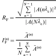
the torque component ratio: engine cycle. Then, according to equations (2), (5) and (6), the calculation of the feature I(n)T only requires K components of X(ì) at lower frequency harmonics for thenth cylinder in an engine cycle, which can be achieved RT=
S
æ
NÕ 1 m=1|
Tp(mìc)|2
|Tp(Nìc)| (4) quickly by DFT:
whereNis the number of engine cylinders andTp(mìc)
X(n)(mìf)= æMÕ 1 k=0 [
ö(n)
k ]2eÕ i2ðmk/M, m=1, 2, ...,K represents the gas pressure torque component at themth
harmonic within each engine cycle. (8)
The second method forTp(ì) calculation is performed
at harmonics of the engine ring frequency, denoted by The calculation of the features R
T and I(n)T requires ìf, giving a set of components ofTp(ì) for each cylinder knowledge of the engine transfer function X(ì) that is within each engine cycle, and thus the calculation is determined by the engine structural parameters. made from each data block corresponding to each indi- However, it is usually not easy to obtain such structural vidual cylinder. As the cylinder-to-cylinder uctuation parameters for some engines. In this case, by neglecting of the gas pressure torque indicates the power generation
the in uence of the reciprocating torque components capability of each individual cylinder, the torque output
Tr(ì) and by considering A(ì) as the estimate of Tp(ì), of each cylinder will be almost equal if the engine runs
two other similar dimensionless features have been under a normal cylinder-to-cylinder uniform condition.
de ned for engine mis re detection: acceleration compo-Nevertheless, if mis re happens in a certain cylinder, the nent ratio,R
F, and acceleration uctuation index,I(n)F : torque output of this cylinder will decrease signi cantly.
For this reason, another dimensionless feature to detect mis re for thenth individual cylinder has been de ned and it is called the torque uctuation index:
RF=
S
æ
NÕ 1 n=1|A(n
ìc)|2
|A(Nìc)| (9)
I(n)T= T¯(n)p 1 N æ
N n=1T
¯(n) p
(5)
I(n)F = 1 A¯(n)
N æ
N n=1A
¯(n) (10)
where T¯(n)p is a parameter re ecting the gas pressure torque output of thenth cylinder, and it can be estimated
from the root mean square (r.m.s.) value of the lower whereA(nì
c) represents the angular acceleration
compo-frequency components, i.e. nent at the nth frequency harmonic nì
c within each engine cycle andA¯(n)is an estimate re ecting the angular T¯(n)p =K1
S
æKm=1|T ¯(n)
p (mìf)|2 (6) acceleration uctuation of thenth cylinder. whereT(n)p (mìf) represents the gas pressure torque
com-ponent at the mth frequency harmonic mìf for thenth cylinder within each engine cycle and Kis the number
of harmonics of ìfutilized. Kcan be determined using 2.3 Feature extraction based on waveform analysis knowledge of the combustion pressure as it propagates
According to equation (3), the instantaneous angular through the engine dynamics to cause angular velocity
acceleration á(õ) can be easily calculated from the uctuations. For example, if the assumption is made that
measurements of instantaneous angular velocity ö(õ). most of the energy in the uctuating gas pressure torque
Figure 1 depicts the waveforms ofá(õ) andö(õ) meas-is contained in the rst three harmonics of ìf, then
ured from a four-cylinder four-stroke diesel engine (see K=3 is suYcient to estimateT¯(n)p.
Table 1) with cylinder 3 mis ring and ltered by the fast LetLbe the number of angular velocity samples per
Fourier transform ltering method. engine cycle and{ö
k:k=0, 1, 2, ...,L 1} be the data As previously discussed, á(õ) is proportional to the block of angular velocity samples per engine cycle. Then,
engine rotating torqueTe(õ). Thusá(õ) would be pro-according to equations (2) and (4), the calculation of
portional to the uctuating component of the gas press-the feature RT only requires N components of X(ì) at
ure torque Tp(õ) if the in uences of the reciprocating lower frequency harmonics within one engine cycle,
torque Tr(õ) and the resistive torque TL(õ) were to be which can be obtained quickly by DFT:
neglected. This helps directly to de ne three dimen-sionless features from the angular acceleration waveform X(mìc)= æLÕ 1
k=0
ö2keÕ i2ðmk/L, m=1, 2, ...,N (7)
for the mis re detection of an individual cylinder. These have been called the maximum acceleration index, Let{önk:k=0, 1, 2, ...,L/N 1;n=1, 2, ...,N}be the
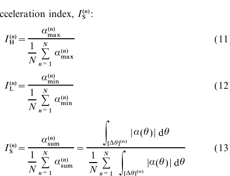
[image:4.566.301.398.300.396.2]angular positions. Then, the maximum variation in the instantaneous angular velocity, ¢ö(n)=ö(n)max ö(n)min, and its corresponding angular duration, ¢õ(n)=õ(n)max õ(n)min, are both indicators of the mean gas pressure torque of thenth cylinder. Therefore, three fea-tures can be de ned to identify whether thenth cylinder is mis ring. They are called the angular variation index I(n)C , velocity variation index, I(n)V and acceleration vari-ation index,I(n)A :
I(n)C = 1 ¢õ(n)
N æ
N n=1
¢õ(n)
(14)
I(n)V= 1 ¢ö(n)
N æ
N n=1
¢ö(n)
(15)
Fig. 1 Waveforms of (a) instantaneous angular acceleration and (b) instantaneous angular velocity during a cycle in a four-cylinder four-stroke engine
I(n)A=
¢ö(n) ¢õ(n) 1 N æN
n=1 ¢ö(n) ¢õ(n)
[image:5.566.41.262.47.233.2](16) Table 1 Speci cation of the test engine
Engine type Model 4135D, 8.6 l, 4-cylinder, 4-stroke, direct injection diesel
Manufacturer Shanghai Diesel Works 3 ON-LINE MISFIRE DETECTION BY
Bore×stroke 135 mm×150 mm
Maximum power output 123.6 kW at 1500 r/min MULTIPLE FEATURE FUSION Maximum torque 582 N m at 1200 r/min
Compression ratio 17:1
3.1 Mis re detection by each individual feature
Firing order 1–3–4–2 (from timing cover)
So far 10 dimensionless features have been de ned along with fast feature extraction algorithms. Here rules are acceleration index, I(n)S :
presented for each individual feature to identify engine mis re. Among these rules, rule 1 is forRT andRF and I(n)H=1 á(n)max
N æ
N n=1
á(n)max
(11) rules 2–4 are for I(n)
T , I(n)F , I(n)H, I(n)L , I(n)S , I(n)C , I(n)V and
I(n)A .
TakingRTas an example, rule 1 for a selected thresh-oldRT,0would be
I(n)L=1 á(n)min
N æ
N n=1
á(n)min
(12)
Rule 1
IFRTå RT,0
THEN all cylinders are healthy
ELSE one or more cylinders is mis ring I(n)S =1 á(n)sum
N æ
N n=1
á(n)sum
=
P
[¢õ](n)|á(õ)|dõ
1 N æ
N
n=1
P
[¢õ](n)|á(õ)|dõ
(13)
TakingI(n)T as an example, rules 2–4 for a selected value åare as follows. Here åis a minor positive value quite near zero. Its introduction is to distinguish the normally where á(n)max, á(n)min and á(n)sum are respectively the peak
acceptable cylinder-to-cylinder non-uniformity from the value, the valley value and the summed absolute value
abnormal mis re and thus to avoid a mistaken diagnosis. of the angular acceleration waveform of thenth cylinder
and [¢õ](n)is the crankshaft angular interval
correspond-Rule 2 ing to thenth cylinder.
As shown in Fig. 1b, in the waveform of instantaneous IF 1
åå I(n)T å 1+åfor all cylinders angular velocity there exists an acceleration during the THEN all cylinders are healthy expansion stroke of each cylinder because of the
combus-tion pressure force. Let ö(n)max and ö(n)min be respectively Rule 3 the peak value and valley value of the angular velocity
waveform during the expansion stroke of thenth cylin- IFI(n)T <1 å
[image:5.566.37.268.402.579.2]Rule 4
IFI(n)T >1+å
Then thenth cylinder is healthy while mis re exists in another cylinder or cylinders
3.2 On-line mis re detection by multiple feature fusion
According to rule 1, among the 10 dimensionless fea-tures, neither RT nor RF is capable of identifying the mis ring cylinder(s), but both of them can detect
Fig. 3 Proposed architecture of multiple feature fusion whether the engine is healthy or faulty with much simpler
computations. According to rules 2–4, on the contrary,
single sensor provides the data (i.e. the instantaneous all of the other eight features have the capability to
ident-angular velocity signal ), from which several single ify the individual mis ring cylinder(s) but with more
features are extracted by diVerent feature extraction complex computations. For this reason, a technique for
approaches. Then these features are associated together the on-line detection of engine mis re has been proposed
into a single feature vector, which in turn is input to a which aims at achieving improved diagnostic eYciency
decision-making procedure, which may be a neural net-and reliability.
work or clustering algorithm. Noticing that the decision The technique is depicted in Fig. 2, where all of the making is in fact a process of pattern recognition; here 10 dimensionless features are used. If the engine
struc-a fuzzy pstruc-attern recognition technique [21] is introduced, tural parameters are known,RTwill identify whether the
which is particularly suitable for the association of engine is healthy or faulty at rst andI(n)T will then locate
multiple dimensionless features. The principles are the position of a mis ring cylinder or cylinders if
neces-demonstrated in the following section. sary. Otherwise, if the engine structural parameters are
unknown, RF will detect whether the engine is healthy,
and the remaining seven features can then be used to 4 MULTIPLE FEATURE FUSION PROCEDURE identify the possible mis ring cylinder(s). The technique
involves a multiple feature fusion process, which is based 4.1 Principles of fuzzy pattern recognition on the feature level fusion architecture for multisensor
fusion [20] but with some modi cation. The problem of fuzzy pattern recognition can be simply described as follows [21]: given K known patterns, As illustrated in Fig. 3, not multisensors but only a
[image:6.566.331.491.47.171.2] [image:6.566.135.433.456.711.2]A1,A2, ..,AK, and one new pattern, B, identify which by seven features together,I(n)F,IH(n),I(n)L,I(n)S ,I(n)C,I(n)V and I(n)A . This is achieved by fuzzy pattern recognition with known pattern the new pattern should be classi ed into.
In this description, each pattern, denoted byA, is a fuzzy the following procedure:
vector 1. The seven features of each individual cylinder are
A=(a1,a2, ...,aM) (17) associated together as a vector:
where each element of the vector,am, satis es U(n)=(u(n)1 ,u(n)2 ,u3(n),u(n)4 ,u(n)5 ,u(n)6 ,u(n)7 )
0å amå 1, m=1, 2, ...,M (18) =(I(n)F ,I(n)H ,I(n)L ,I(n)S ,I(n)C ,I(n)V ,I(n)A) (24) The fuzzy vectorAcan be interpreted as a fuzzy set in 2. U(n) is transformed into a fuzzy vector
the domainU=[u1,u2, ...,uM}
B(n)=(b(n)1 ,b(n)2 ,b(n)3 ,b(n)4 ,b(n)5 ,b(n)6 ,b(n)7 ) A=
G
au11,
a2 u2, ...,
aM
uM
H
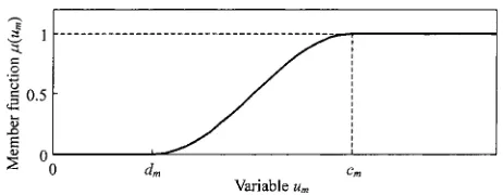
(19) with each elementfuzzi ed by the uphill distribution member functionu(n)m (m=1, 2, ..., 7) ofU(n) being (its property is shown in Fig. 4)where the transformation of am to um is often termed
fuzzi cation [22], which depends on a membership b(n)
m =í(u(n)m ) function
am=í(um) (20)
Once all of the known patterns and the new pattern have
been represented as fuzzy vectors, the pattern recog- =
G
0, 0å u(n)m <dm 1
2+ 1 2sin
C
ð
cm dm
×
A
u(n)m cm+2dmBD
, dm<u(n)m <cm 1, u(n)m" cm(25) nition can be achieved by computing and comparing the
degree of closeness between the new fuzzy vectorBand each known fuzzy vectorAk(k=1, 2, ...,K). If there is a known vectorAj withjµ{1, 2, ...,K}satisfying
wherecmanddmare both constant and can be deter-ó(B,A)= max
1¢k¢M(B,Ak) (21) mined by the relationship ofu(n)m among Ncylinders: then B is the nearest to Aj among all of the known c
m=1max¢n¢N(u(n)m) patterns, that is to say the new pattern B should be
classi ed into the known pattern Aj. This is called the d m=13cm
nearest selection criterion in fuzzy pattern recognition. (26)
In equation (21), ó is called the degree of closeness
3. The degree of closeness ó1 (or ó2) is calculated between two fuzzy vectors [21]. Although there are many
between the new fuzzy vector B(n) and a standard de nitions for the degree of closeness, each of them is
known fuzzy vector A. This standard vector A is generally intended for a particular purpose. Here two
de ned under a healthy engine condition with absol-de nitions are used for engine mis re detection:
ute cylinder-to-cylinder uniformity. Under such a 1. Maximum–minimum degree of closeness ó1 condition, all of the seven features,I(n)
F, I(n)H,I(n)L,I(n)S ,
I(n)C,I(n)V andI(n)A , should theoretically be unity for all of the N cylinders, and their fuzzi ed values should ó1(A,B)=
æM
m=1min(am,bm) æM
m=1
max(am,bm)
(22) still be unity. Therefore, the standard vectorAof all cylinders can have the form
A=(1, 1, 1, 1, 1, 1, 1) (27)
2. Euclidean distance degree of closenessó2
4. The following rule identi es whether thenth cylinder is healthy or mis ring, where ó0 is a dimensionless ó2(A,B)=1
S
M1 æMm=1(am,bm)
2 (23)
where A=(a1,a2, ...,a
M) and B=(b1,b2, ...,bM) are two fuzzy vectors.
4.2 Mis re detection by multiple feature fusion with fuzzy pattern recognition
As depicted in Fig. 2, if the engine structural parameters are unknown, whether an individual cylinder is healthy
[image:7.566.298.529.621.711.2]threshold and may be statistically determined from experimental data.
Rule 5
IFó1" ó0(or ó2" ó0)
THEN thenth cylinder is healthy ELSE thenth cylinder is mis ring
5 EXPERIMENTAL RESULTS AND DISCUSSION
5.1 Measured signals from a production engine
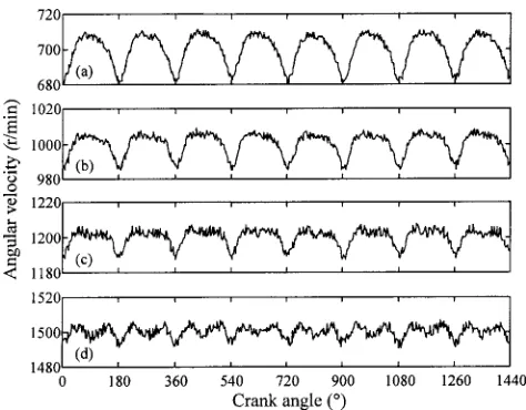
To obtain instantaneous angular velocity signals to vali- Fig. 5 Measured instantaneous angular velocity without mis-date the proposed on-line mis re detection technique, an re for mean engine speeds of (a) 700, (b) 1000, engine test facility was set up. The speci cation of the (c) 1200 and (d) 1500 r/min
test engine, a model 4135D four-cylinder four-stroke diesel engine, produced by Shanghai Diesel Works and used in light commercial vehicles, is given in Table 1. The engine was loaded with a hydraulic dynamometer and was appropriately instrumented to record the operating parameters. To allow the proposed technique to be validated over a wide range of engine operation conditions, the measurement of instantaneous angular velocity was performed over a selection of speed and load settings.
An eddy current displacement sensor mounted opposite the ywheel was used to measure instantaneous angular velocity signal, and a Hall eVect device on the camshaft provided a timing reference point at the top dead centre (TDC ) of cylinder 1. This device had the characteristic that the angular velocity resolution decreases as the engine speed increases. A personal com-puter (PC ) mounted with a Real Time Devices AD3110
Fig. 6 Measured instantaneous angular velocity with cylinder analogue-to-digital conversion data acquisition (DAQ )
3 mis ring for mean engine speeds of (a) 700, (b) 1000, board was used for data collection and analysis. As the (c) 1200 and (d) 1500 r/min
ywheel had 128 teeth and the AD3110 DAQ board
provided a timer counter of 8 MHz clock rate, the mini- 5.2 Mis re detection capability by each individual mum angular velocity resolution was 0.6 r/min at the feature
highest engine speed of 1500 r/min. This resolution is,
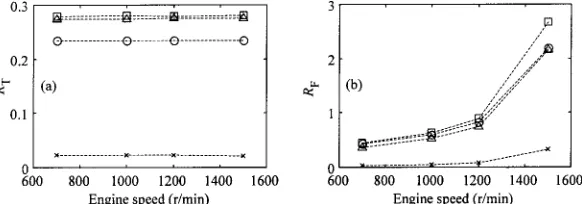
however, considered suYcient for mis re detection, since Figure 9 shows the calculated featuresR
TandRFfor the the angular velocity variation observed was more than range of operating conditions as described in Figs 5 to 20 r/min even with the engine running in a healthy 8. It is clear that the calculated values of these two fea-condition under very low load. tures for a healthy engine are almost 10 times as great Figures 5 to 8 present waveforms of instantaneous as those for a faulty engine. Therefore, the features RT angular velocity measured under the same load of and RF can easily detect whether mis re exits in the 30 N m over a range of operating conditions (i.e. without engine, although, as previously explained, neither can mis ring, with cylinder 3 mis ring, with cylinders 2 and identify which cylinder is mis ring. It is also observed 3 spatially mis ring, and with cylinders 3 and 4 sequen- that the in uence of the engine speed, especially higher tially mis ring). Each gure includes four plots corre- speeds, should be considered carefully when using the sponding to mean engine speeds of 700, 1000, 1200 and feature RF, but this caution is not necessary for the 1500 r/min. Two cycles of sampled data are depicted in featureRT.
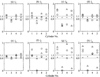
[image:8.566.294.531.46.231.2] [image:8.566.294.528.285.474.2]1500 r/min under the same range of conditions as described in Figs 5 to 8. It is observed that all these features have the capability of both detecting engine mis- re and locating its position. Among the eight features I(n)T is observed to be more accurate for identifying the mis ring cylinder(s) than the other seven features, but its computation is more complex since it requires knowl-edge of engine structural parameters. Some features, par-ticularly I(n)C, I(n)V and I(n)A, which are directly extracted from the angular velocity waveform, could not be calcu-lated under certain engine conditions. This occurs when there is no obvious acceleration in the angular velocity waveform and especially at high engine speeds or a cer-tain cylinder is mis ring. As shown in Fig. 11, these fea-tures are xed at zero in such cases, but this simple adjustment may possibly give an erroneous diagnosis.
It is interesting to note that the diagnostic conclusions Fig. 7 Measured instantaneous angular velocity with cylin- implied by diVerent single features do not always concur ders 2 and 3 spatially mis ring for mean engine speeds and sometimes they directly con ict with one another. of (a) 700, (b) 1000, (c) 1200 and (d) 1500 r/min For example, the feature I(n)
A would give an erroneous diagnostic decision with the engine at 1500 r/min when cylinders 3 and 4 both mis re (shown in Fig. 11), whereas other features can detect this fault correctly. This indicates that the information provided by multiple features is usually redundant and complementary, but sometimes contradictory, and one single feature may hence simply not be suYcient to make a reliable mis re decision.
5.3 Mis re detection capability by multiple feature fusion
Since the forcing of incomputable features to be zero increases the probability of an erroneous diagnosis, a feature selection process can be performed before the multiple feature fusion procedure described in sec-tion 4.2. This can be achieved by excluding the incom-Fig. 8 Measured instantaneous angular velocity with cylin- putable features from the feature vector shown in
ders 3 and 4 sequentially mis ring for mean engine equation (24). For example, if three featuresI(n)
C,I(n)V and speeds of (a) 700, (b) 1000, (c) 1200 and (d) 1500 r/min I(n)
A are incomputable, the fuzzy vector of thenth cylinder
[image:9.566.33.267.46.237.2] [image:9.566.32.266.298.490.2] [image:9.566.138.429.553.655.2]Fig. 10 Calculated featuresI(n)T,I(n)F,I(n)H, I(n)L, I(n)S , I(n)C,I(n)V andI(n)A at a speed of 1000 r/min (×, without mis re;# , with cylinder 3 mis ring; , with cylinders 2 and 3 mis ring;%, with cylinders 3 and 4 mis ring)
Fig. 11 Calculated featuresI(n)T,I(n)F,I(n)H, I(n)L, I(n)S , I(n)C,I(n)V andI(n)A at a speed of 1500 r/min (×, without mis re;# , with cylinder 3 mis ring; , with cylinders 2 and 3 mis ring;%, with cylinders 3 and 4 mis ring)
would beB(n)=(í[I(n)F ],í[I(n)H ],í[I(n)L ],í[I(n)S ]), which con- and the standard vectorAwill identify whether thenth cylinder is mis ring.
tains only four elements. Meanwhile, the standard vector
Fig. 12 Calculated degrees of closenessó1andó2at speeds of 1000 and 1500 r/min (×, without mis re;# , with cylinder 3 mis ring; , with cylinders 2 and 3 mis ring;%, with cylinders 3 and 4 mis ring)
at 1000 and 1500 r/min and under the same range of engine cycle, which is, for instance, 80 ms with the four-stroke engine at 1500 r/min. From this point of view, the conditions as described in Figs 5 to 8. It is observed that
all these values are less than 0.5 for a mis ring cylinder proposed algorithms are veri ed to be fast in compu-tation and have the potential capability for on-line but more than 0.8 for a healthy cylinder. This diVerence
is so distinct that the selection of a threshold for ó1or monitoring and real-time diagnosis of engine mis re. ó2 is much more straightforward than for a single
feature.
6 SUMMARY AND CONCLUSIONS
It is also noted that the proposed multiple feature fusion technique exploits the redundant and
complemen-tary information of all the single features and thus leads In this paper, a technique for the on-line detection of engine mis re based on multiple feature fusion has been to improved diagnostic reliability. For example, the
pro-posed technique can identify the mis ring cylinders 3 proposed. Ten dimensionless features with fast compu-tational algorithms have been de ned and if all these and 4 correctly with the engine at 1500 r/min. This is
important because such a conclusion is obtained when features are associated together they can rstly identify reliably whether the engine is healthy or mis ring and the individual feature I(n)A gives an erroneous diagnosis
(shown in Fig. 11). A similar case can be seen when the secondly locate the position of a mis ring cylinder or cylinders.
engine ran at 1500 r/min with cylinder 3 mis ring.
As described in Fig. 2, only after a data block of Although all of the single features can be used to detect mis re, none of these features is found to be uni-instantaneous angular velocity within one engine cycle
is available will the PC system start to analyse the data, versally successful because of the complex nature of the in-cylinder process. The diagnostic results from single calculate the features and, nally, draw a conclusion on
whether the engine is healthy and which cylinder is mis- features are not always concurrent and sometimes actually con ict with one another.
ring. This indicates that the proposed technique for
engine mis re detection is on a cycle-by-cycle basis. In The fusion of multiple features has been demonstrated to provide signi cant advantages over the use of single this study, without knowledge of the engine structural
parameters, the total computation time during one features. In this way it exploits the redundant and comp-lementary information of all the features and thus leads engine cycle is 5.7 ms when using a PC system with an
Intel Pentium 10 MHz CPU and 32M RAM running to improved diagnostic reliability.
The proposed multiple feature technique has been under Microsoft Windows 95. Obviously this
com-for monitoring the condition of military vehicle engines. putation, and it may hence provide a basis for a practical
Proc.Instn Mech.Engrs, 1986,200(D1), 45–51.
utility in on-line monitoring and real-time diagnosis of
9 Rezeka, S. F. and Henein, N. A. A diagnostic technique engine mis re.
for the identi cation of mis ring cylinder(s). SAE paper Owing to the limitation that the maximum speed of
870546, 1987.
the test engine is only 1500 r/min, further work is still to 10 Citron, S. J., O’Higgins, J. E.andChen, L. Y.Cylinder by be undertaken on other high speed engines so that the cylinder engine pressure and pressure torque waveform proposed technique will also be eVective in high speed determination utilizing speed uctuations. SAE paper
conditions. 890486, 1989.
11 Mauer, G. F.On-line cylinder fault diagnostics for internal combustion engines.IEEE Trans. Ind. Electronics, 1990, 37(3), 221–226.
ACKNOWLEDGEMENT
12 Rizzoni, G.andConnolly, F. T. Estimation of IC engine torque from measurement of crankshaft angular position. This research was supported by the National Key Project SAE paper 932410, 1993.
of China (PD9521908). 13 Shiao, Y.andMoskwa, J. J.Mis re detection and cylinder pressure reconstruction for SI engines. SAE paper 940144, 1994.
14 Connolly, F. T. andYagle, A. E.Modelling and identi
-REFERENCES
cation of the combustion pressure process in internal com-bustion engines.Mech. Systems Signal Processing, 1994, 1 Sood, A. K., Fahs, A. A. and Henein, N. A. A real-time 8(1), 1–19.
microprocessor-basedsystem for engine de ciency analysis. 15 Rizzoni, G. andZhang, Y. Identi cation of a non-linear
IEEE Trans.Ind.Electronics, 1983,30(2), 159–163. internal combustion engine model for on-line indicated
2 William, P. andStephen, J.An on-line engine roughness torque estimation.Mech.Systems Signal Processing, 1994,
measurement technique. SAE paper 840136, 1984. 8(3), 275–287.
3 Ribbens, W. B. and Rizzoni, G. Application of precise 16 Connolly, F. T. and Rizzoni, G. Real-time estimation of crankshaft position measurements for engine testing, engine torque for the detection of engine mis res.Trans. control and diagnosis. SAE paper 890885, 1989. ASME, J. Dynamic Systems, Measmt, Control, 1994, 4 Kao, M.andMoskwa, J. J.Nonlinear diesel engine control 116(4), 675–686.
and cylinder pressure observation analysis.Trans.ASME, 17 Shiao, Y.andMoskwa, J. J.Cylinder pressure and
combus-J. Dynamic Systems, Measmt, Control, 1995, 117(2), tion heat release estimation for SI engine diagnostics using
183–192. non-linear sliding observers.IEEE Trans.Control Systems
5 Sood, A. K., Friedlander, C. B. and Fahs, A. A. Engine Technol., 1995,3(1), 70–78.
fault analysis: I—statistical method. IEEE Trans. Ind. 18 Luo, R. C. andKay, M. G. Multisensor integration and
Electronics, 1985,32(4), 294–300. fusion in intelligent systems.IEEE Trans.Systems, Man
6 Freestone, J. W.andJenkins, E. G.The diagnosis of cylin- Cybernetics, 1989,19(4), 901–931.
der power faults in a diesel engine by ywheel speed 19 Dasarathy, B. V.Paradigms for information processing in measurement. Proc. Instn Mech. Engrs, 1986, 200(D1), multisensor environments.Proc.SPIE, 1990,1306, 69–80.
37–43. 20 Hall, D. L.andLlinas, J.An introduction to multisensor
7 Henein, N. A., Bryzik, W., Taylor, C. and Nichols, A. data fusion.Proc.IEEE, 1997,85(1), 6–23.
Dynamic parameters for engine diagnostics: eVect of sam- 21 Wang, P.Fuzzy sets and their applications, 1983 (Shanghai
pling. SAE paper 932411, 1993. Science and Technology Press, Shanghai).