Computational Fluid Dynamics Based Optimal Design of Vertical
Axis Marine Current Turbines
Taimoor Asim*, Rakesh Mishra, Kuldip Ubbi, Karina Zala
School of Computing & Engineering, University of Huddersfield, UK (HD1 3DH)
* Corresponding author. Tel.: +0044-1484-472727. E-mail address: t.asim@hud.ac.uk
Abstract
Marine turbines are being increasingly used to harness kinetic energy of water and convert it into other useful forms of energy. Widespread commercial acceptability of these machines depends upon their efficiency. This largely depends upon the geometric features of the marine turbines such as number of blades, shape of blades etc. Researchers have been using experimental facilities to optimise these machines for maximum power generation. With the advent of advanced computational techniques, it has now become possible to numerically simulate the flow of water in the vicinity of marine turbines and monitor their performance output. In this work Computational Fluid Dynamics (CFD) based techniques have been used to analyse the effects of number of blades within the stator and rotor, of an in-house built Vertical Axis Marine Current Turbine (VAMCT), on the performance output of the turbine. Furthermore, an effort has been put forward towards better understanding of the flow structure in the vicinity of the blades during transient interaction between rotor and stator blades. This study provides vital information with regards to the flow sensors’ requirements and placements in order to monitor various blade configurations of a VAMCT in real world. The results of this study show that the torque output from a VAMCT is a strong function of blade configurations and there is a significant degradation in the performance output of marine turbines as the inequality between the number of rotor and stator blades increases. Hence, CFD has the potential to optimise the design of marine turbines and can be used as a potential modelling tool in the near future for on-line health monitoring of such systems.
Keywords: Vertical Axis Marine Current Turbine (VAMCT), Computational Fluid Dynamics (CFD), Torque Output, Tip Speed Ratio
1. Introduction
Marine Current Turbines (MCTs) convert the kinetic energy of the tidal waves into useful energy forms. Two common types of MCTs are Horizontal Axis and Vertical Axis Marine Current Turbines. The principle of operation of both these turbines is the same as for Horizontal Axis and Vertical Axis Wind Turbines i.e. HAWT and VAWT. The use of Darrieus type Vertical Axis Marine Current Turbines (VAMCTs) provides several advantages over Horizontal Axis Marine Current Turbines (HAMCTs) such as the low starting torque, quite operation and insensitivity to the angle of incident flow. Hence, VAMCTs are better suited to extract power from tidal energy.
In the present study a novel Darrieus type VAMCT has been numerically simulated using a commercial CFD package. The VAMCT consists of variable number of rotor and stator blades in various configurations. These configurations are described in table 1 where the first number indicates the number of stator blades and the second number indicates the number of rotor blades. The core, rotor and stator diameters are 1m, 1.4m and 2m respectively whereas the height of the turbine is 0.5m. Figure 1 depicts the geometry of the VAMCT with configurations 4-4, 8-8 and 12-12. The important performance parameters of vertical axis turbines, as mentioned by Colley et. al. [1], are the tip speed ratio (TSR) and the torque output. TSR is the ratio between the rotational speed of the tip of the blade and the actual velocity of the wind..
where r is the radius of the vertical axis turbine, w is the angular velocity and v is the linear flow velocity. Torque output of the wind turbine has a significant impact on the total power output of the turbine:
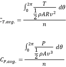
where P is the power and T is the torque output. In the present study, the torque and power outputs from the VAMCT models have been shown in dimensionless form as follows:
and:
[image:2.595.246.352.105.213.2]
where R is the radius of the rotor blades, A is the frontal area of the VAMCT, θ is the angular position of the VAMCT and n is the number of time steps through which VAMCT has been rotated in order to complete one revolution.
Table 1. Various VAMCT configurations. Configuration Number of Stator Blades Number of Rotor Blades
4-4 4 4
4-8 4 8
4-12 4 12
8-4 8 4
8-8 8 8
8-12 8 12
12-4 12 4
12-8 12 8
12-12 12 12
(a) (b) (c) Fig. 1. VAMCT configurations (a) 4-4 (b) 8-8 (c) 12-12
2. Numerical Modeling
In order to analyse the effect of the number of stator and rotor blades on the performance output of a VAMCT, a commercial CFD tool has been used to numerically simulate the flow of water in the vicinity of VAMCT models. The analysis has been carried out for TSRs of 0.01, 0.1, 0.2, 0.4 and 0.6. The geometric configuration of the stator blades considered in the present study shows that these blades are curved at an angle of 20º with respect to the interface between the stator and the rotor, whereas the rotor blades have been curved at 28.2º. VAMCTs have been considered to be operating at 1m under the sea level where the flow velocity has been considered to be 1m/sec.
[image:2.595.96.502.276.575.2]complex flow phenomena. Three dimensional Navier-Stokes equations have been iteratively solved for transient motion of VAMCT’s blades.
Figure 2 depicts the flow domain that has been numerically simulated for water flow in the vicinity of the VAMCT. The domain dimensions are the same as considered in Park et al [4] where the walls of the domain have been configured as moving walls having the same velocity as that of water flow in the domain. This reduces the effects of the boundary layer formation on the walls as the walls have been specified with no-slip boundary condition.
Fig. 2. Flow domain for VAMCT.
3. Results and Analysis
3.1. Blade Interaction
In order to analyse the interaction between the rotor and the stator blades of a VAMCT, three different angular positions have been chosen in the VAMCT model with configuration of 4-4. These blade positions corresponds to -9⁰, 0⁰ and 9⁰, as shown in figure 3, where -9⁰ indicates the angular position when rotor blades are 9⁰ behind the stator blades, while approaching them in an anticlockwise manner. 0⁰ corresponds to the angular position when both the rotor and the stator blades are in-line with each other i.e. the angular difference between the rotor and the stator blades is 0⁰. Furthermore, 9⁰ correspond to the angular position when rotor blades are 9⁰ ahead of the stator blades.
[image:3.595.151.442.175.383.2]
Fig. 3. Angular positions of the rotor blades.
[image:3.595.219.385.543.709.2]locations of both the upper and the lower rotor/stator blades, there exists a very high pressure region, whereas at the downstream of these blades, the pressure is very low. Furthermore, the pressure on the front rotor/stator blades is appreciably higher as compared to the pressure on the rear rotor/stator blades.
It can be further seen that as the rotor blades approach the stator blades, the pressure at the interface between the rotor and the stator blades increases. This increase in the pressure reduces the flow velocity due to more resistance offered by the blades to the incident flow.
(a) (b)
[image:4.595.102.497.158.502.2](c)
Fig. 4. Pressure variations in the vicinity of VAMCT at (a) -9⁰ (b) 0⁰ (c) 9⁰.
In order to analyse the local pressure variations near VAMCT, a few locations have been strategically chosen where static pressure exerted by the flow is being monitored. These locations are shown in figure 4, where locations 1 to 4 i.e. P1 to P4, are aligned horizontally and locations P5 to P6 have been aligned vertically.
[image:4.595.201.397.569.753.2]The results presented in table 2 show that the pressure at location P1 keeps on increasing as the rotor blade’s angular position increases with respect to the stator blades. Pressure at location P2 decreases with increasing rotor blade’s angular position, whereas there is negligibly small variation in pressure at locations P3 (13Pa) and P4 (14Pa). In vertical direction, it can be seen that at locations P5 and P6, the pressure keeps on decreasing with increasing angular position of the rotor blades. There is negligibly small variation of pressure at location P7 whereas at location P8 pressure keeps on decreasing. Hence, it can be concluded that the interaction between the rotor and the stator blades decreases the overall flow pressure and hence increases the flow velocity in the vicinity of VAMCT. This is due to the fact that when the stator and the rotor blades come in-line with each other, uniform flow passages are revealed to the incident flow, through which the flow can take place with comparatively less resistance, thus increasing the flow velocity and decreasing the pressure.
Table 2. Pressure variations at various locations.
Blade Position (°)
Static Pressure on Points (Pa)
P1 P2 P3 P4 P5 P6 P7 P8
-9 26 129 69 -152 -82 -550 86 -1
0 71 105 60 -158 -143 -611 103 -41
9 81 74 56 -144 -181 -611 83 -89
Maximum 81 129 69 -144 -82 -550 103 -1
Minimum 26 74 56 -158 -181 -611 83 -89
Max - Min 55 55 13 14 99 61 20 88
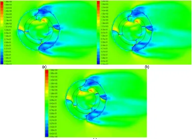
Figure 5 depicts the variations in the velocity field in the vicinity of the VAMCT at different angular positions shown in figure 3. It can be seen that the velocity field near VAMCT is highly non-uniform such that in the vicinity of the upper, lower and rear rotor/stator blades, the flow velocity is very low, whereas at the front stator/rotor blades, the flow velocity is comparatively higher. Furthermore, it can be seen that as the rotor blades approaches the stator blades, the flow velocity near the upper rotor/stator blades increases and keeps on increasing even after the rotor blades pass by the stator blades.
(a) (b)
(c)
The results presented in table 3 show that in the horizontal direction, the flow velocity is higher on the upstream sides as compared to the downstream sides. Furthermore, it can be seen that the flow velocity in the core region of the VAMCT is comparatively lower than the flow velocity in the vicinity of the stator region. It can also be seen from the table that at location P6 and P7 the velocity variations are highest.
Table 3. Velocity variations at various locations.
Blade Position
(°)
Velocity Magnitude on Points (Pa)
P1 P2 P3 P4 P5 P6 P7 P8
-9 1.01 0.66 0.74 0.47 0.91 0.87 0.82 0.99
0 0.99 0.78 0.73 0.40 0.97 0.57 0.64 1.06
9 1.00 0.72 0.72 0.39 0.96 0.57 0.66 1.07
Maximum 1.01 0.78 0.74 0.47 0.97 0.87 0.82 1.07
Minimum 0.99 0.66 0.72 0.39 0.91 0.57 0.64 0.99
Max - Min 0.02 0.12 0.02 0.08 0.06 0.30 0.18 0.08
3.2. Performance Output
In order to quantify the performance output from various VAMCT models considered in the present study, figures 7 and 8 depict the average torque and power coefficients from these models at various TSRs. The range of TSRs has been chosen such that to compare the results of this study with that of Park et al (2012) in which straight stator blades were considered.
[image:6.595.159.437.463.676.2]It can be seen from figure 7 that as the TSR of the VAMCT increases, the average torque coefficient decreases. Further analysing the figure suggests that as the number of rotor blades increases, the torque output from the VAMCT increases. It is however noteworthy that the highest torque output from the VAMCT is generated when the number of rotor and stator blades is kept the same.
Fig. 7. Variations in Average CT at various TSRs.
As mentioned earlier, the results of this study have been compared with that of Park et al [5] in which straight stator blades was considered. Figure 9 depicts the comparison between the two results. It can be seen that curved stator blades result in higher power output and delays the onset of churning. On average, average power output from curved stator blades is 87% higher as compared to straight stator blades.
Fig. 8. Variations in Average CP at various TSRs.
Fig. 9. Comparison between Straight and curved Stator Blades.
4. Conclusions
References
[1] Colley, G. and Mishra, R. Computational flow field analysis of a Vertical Axis Wind Turbine, In proceedings of the International Conference on Renewable Energies and Power Quality (2011); Las Palmas, Gran Canaria.
[3] Ponta, F. Dutt, G. S. An Improved Vertical Axis Water Current Turbine Incorporating a Channelling Device, Renewable Energy (2000); 20: 223-241.
[3] Shiono, M. Suzuki, K. Kiho, S. Output Characteristics of Darrieus Water Turbine with Helical Blades for Tidal Current Generation, 12th International Offshore and Polar Engineering Conference (2002); Japan.
[4] Park, K.S. Asim, T. and Mishra, R. Computational Fluid Dynamics based fault simulations of a Vertical Axis Wind Turbine, Journal of Physics: Conference Series (2012); 364.