1401 DATA PROCESSING SYSTEM BULLETIN
1401 DATA FLOW
New, more efficient programming techniques for the
IBM 1401 Data Processing System are being developed as the programming knowledge and the experience level on the system increases. This manual presents a semi-detailed data How explanation of every 1401 oper-ation. This approach should assist both the new, and the more experienced, programmer with his 1401 pro-gramming effort.
Each operation is presented in the form of a data-How diagram. The path that the data takes during an operation is graphically presented along with a written explanation of the steps involved. The internal-parity and validity-checking operations are also presented, along with a list of the console lights that will be ON in
the event of a parity or validity check condition.
Data Flow
The data How of an IBM 1401 Data Processing System is schematically shown in Figure 1. The How paths used are initially specified by the stored program instruc-tions. These instructions tell the system what areas to read out of, and what areas to read into. The internal circuitry of the system then carries out the specified data movement. The various component areas of the system are:
CORE STORAGE
The IBM 1401 Data Processing System uses magnetic-core storage for storing instructions and data. All the data in core storage is readily available, and the design of the core-storage area makes each position individu-ally addressable. All data received from input units is stored in the core storage, and all data sent to the out-put units is sent from core storage.
Information is always read out of core storage dur-ing the early haH of a cycle. The read-out is actually accomplished by setting all the cores, at the specified location; to zero. A core originally set at one will, when flipped from one to zero during read-out, induce a
volt-© 1962 by International Business Machines Corporation
age on one of the wires running through the center of the core. This voltage is recognized as a bit.
Information is always read into core storage during the late haH of a cycle. If the information that was read out of a storage location is to be retained in the same location, it is read back into that location from one of the registers during the late haHof the read-out cycle. The 1401 system also makes use of this core-storage operation to perform the system's arithmetic opera-tions. Two areas are alternately read out a position at a time, added together, and the sum stored in the last position read out. This is called add-to-storage logic, and it eliminates the need for special-purpose accumu-lators or counters. Because any group of storage posi-tions can be used as an accumulating field, the capacity for arithmetic functions is not limited by a predeter-mined number of counter positions.
DATA LINES AND INHIBIT DRIVE
The data-How paths shown in Figure 1 as single lines are actually eight lines (4 digit, 2 zone, 1 word mark, and 1 check). The lines leading to the inhibit drive are called inhibit lines because they inhibit, or prevent, the setting of cores unless activated by the presence of a bit of information. Information being sent into core storage goes through the inhibit-drive area, while in-formation being sent from core storage goes through the B-register.
B-REGISTER
Each character leaving 1401 core storage enters the B-register and is stored in an 8-bit code (BCD code, word mark, check bit). The register is reset and filled with a character from core storage during the read-out portion of every storage cycle. The character can be entered back into core storage from the output of the B-register during the storage read-in portion of a stor-age cycle. This is necessary when an instruction is being read and will be needed another tLT!le, because the cores of a position are all set to zero when that position is read out.
I Hole Count I
~
I I,
I
READER Hole CountI
I
I
Printer ChecksPUNCH
!
-l
I
VaiidityI
I
PRINTERINHIBIT
!
DRIVE Parity Check
----
LOGIC-CORE STORAGE Validity Check
B-
A-REG REG
Parity Check Parity Check
STORAGE-ADDRESS REGISTER
(STAR)
INSTRUCTION LENGTH Parity And Validity
b
1, '
I
MANUAL ADDRESS SWITCHES 3 4 56
0 0 0 0
I
W
REG±l
I
I
I
+3 Parity And
0 Validity
Modifier
I
1
INSTRUCTlON- A-
B-ADDRESS ADDRESS ADDRESS
REGISTER REGISTER REGISTER
- --, " - ... , ,... . ... ~
Q~I
I\~ AUU Kt:I.:>i
!
Figure 1. Data Flow and Checking Features
A-REGISTER
The A-register is reset and filled with the character from the B-register during each cycle that involves an A-address, and during all instruction cycles, except the first and last cycle of each instruction. The character is stored in an 8-bit code. The character can be entered back into core storage from the output of the A-register during the storage read-in portion of a storage cycle.
OP-REGISTER
The Op- (operation) register is reset and filled with a 7-bit character output from the B-register (word mark is dropped), whenever the character is an operation-code character. The Op-register stores the operation code of the instruction in process for the duration of the operation.
LOGIC AREA
The logic area is made up of the circuitry that executes the adding, subtracting, and comparing of the A- and B-register outputs. Depending on the operation, the re-sultant logic-area output may be entered back into stor-age and/or may indicate the next step to be taken.
I-ADDRESS REGISTER
The I-(Instruction) address register (I-Add. Reg.) is a 3-position register, and always contains the core storage location of the next instruction character to be read out. (This 3-digit core-storage location is converted to its 4-or 5-digit number when it is displayed in the st4-orage- storage-address register.) The location number is increased by one as the instruction is read out of core storage, lower-order core-storage position to higher-lower-order core-storage position.
A-ADDRESS REGISTER
The A-address register (A-Add. Reg.) is a 3-position register, and normally contains the core-storage loca-tion specified in the A-address porloca-tion of an instrucloca-tion. (This 3-digit core-storage location is converted to its 4-or 5-digit number when it is displayed in the st4-orage- storage-address register.) Normally, this core-storage location is the units position of the A-field. As the instruction is executed, the number in this register is decreased by one during each storage cycle that involves the A-ad-dress. During several operations, the A-Add. Reg. oper-ation differs. These differences are discussed as they are encountered. Note: If the A-address portion of the instruction does not contain a 1401 st~rage address (%Ux, for example), the numeric portion of the A-Add. Reg. contents is not disturbed as the instruction is exe-cuted.
B-ADDRESS REGISTER
The B-address register (B-Add. Reg.) is a 3-position
register, and normally contains the core-storage loca-tion specified in the B-address porloca-tion of an instrucloca-tion. (This 3-digit core-storage location is converted to its 4-or 5-digit number when it is displayed in the st4-orage- storage-address register.) Normally, this core-storage location is the units position of the B-field. As the instruction is executed, the number in this register is decreased by one during each storage cycle that involves the
B-address. During several operations, the B-Add. Reg. operation differs. These differences are discussed as they are encountered.
STORAGE-ADDRESS REGISTER
The storage-address register (STAR) is a 3-position reg-ister, and contains the address of the core-storage loca-tion that is being read out and/or read into on any par-ticular storage cycle. (This 3-digit core-storage location is converted to its 4- or 5-digit number when it is displayed.) This address is received from one of the address registers. As the STAR addresses core storage, the address is also modified and read back into the ap-propriate address register.
ADDRESS- MODIFICATION AREA
Because each character in core storage has a different address, the circuitry that specifies the address must be constantly changing. Instructions are placed in storage with the Op code occupying the lowest-numbered lo-cation and the rest of the instruction occupying the ad-jacent higher-numbered locations. To read out the Op code and then the rest of the instruction in sequence the lowest-numbered location must be addressed first' and then each succeeding location must be addressed: Therefore, during the read out of instructions, the ad-dress must be modified
+
1 each time so that the adja-cent higher-numbered location is read out.The data fields, however, are placed in core storage the opposite way. The units position of the field occu-pies the highest-numbered core-storage location, and the rest of the field occupies the adjacent lower-num-bered core-storage locations. To perform the arithmetic functions correctly, the units digit of a field must be worked 0 n rs, IOllowea oy Ine rens 19lt, etc. Tnere-fi t r 11 1 1 .1 • d" 1 fore, the address must now be modified by -1 each time so that the adjacent lower-numbered location is read out.
Operations involving the printer require that the ad-dress must be increased by three each storage cycle, and still other operations require no address modifica-tion.
INSTRUCTION -LENGTH LIGHTS
These lights indicate which position of an instruction is being read out of core storage.
MANUAL-ADDRESS SWITCHES
The four manual-address switches select the address entered in the storage-address register. These switches are effective only with these selected positions of the mode switch:
storage supplies each character for the various output units that can be attached to a 1401 system. The char-acter is converted from its BCD form to a form that is acceptable by the output unit.
PARITY AND VALIDITY CHECKING
1. Character display 2. Alter
3. Address stop 4. Storage print-out 5. Storage scan.
INPUT-OUTPUT UNITS
The various input units send data into the 1401 system where each character is converted to its BCD form and then stored in a specified core-storage location. Core
The internal self-checking features within the process unit consist of parity and validity checking. Each char-acter is checked, at various locations in the process unit, to be sure it has an odd number of bits, and that it is a valid 1401 character. An even number of bits initiates a parity-check condition, and an incorrect bit configura-tion initiates a validity-check condiconfigura-tion. Refer to Figure 2 for a list of the process-unit check conditions.
Additional checking of the input-output units is done. Refer to the appropriate sections for more detail.
TYPE OF tv\ACHINE STOPS STORAGE-ADDRESS LIGHTS ON
UNIT CHECK STOP SWITCH REGISTER (STAR) RESET BY
CHECK WHEN STOPPED REMARKS
ON CE PANEL ON CONTAINS
END OF NEXT PROCESS
A-REG PARITY A-REGISTER CHECK RESET A-REGISTER CONTENTS IN ERROR STILL CYCLE
CHECK RESET KEY ON DISPLAY ORDINARILY END OF CYCLE IN ADDRESS LOCATION PROCESS
CHECK RESET
B-REG PARITY WHICH CHECK IS THAT WAS READ B-REGISTER B-REGISTER CONTENTS IN ERROR STILL DETECTED I NTO THE B-REGISTER CHECK RESET KEY ON DISPLAY IN B-REGISTER
B-ADDRESS REGISTER INDICATES ONE LESS THAN THE LOCATION THAT THE RESULT READ INTO EXCEPT: 1. WHEN THE CHECK IS DETECTED IN
THE LAST CYCLE OF THE FIRST FORWARD SCAN DURING A RECOM-PLEMENT OPERATION. INDICATED END OF FOLLOWING PROCESS CHECK RESET LOCATION IS THE ERROR LOCATION
LOGIC VALIDITY NEXT A-ADDRESS LOGIC
CYCLE CHECK RESET KEY 2. DURING A REVERSE SCAN OPERATION
I INDICATED LOCATION IS ONE MORE
THAN THE LOCATION THAT THE RESULT READ INTO
THE BIT COMBINATION THAT CAUSES THE CHECK IS IN THE STORAGE UNIT AND IS NOT ON DISPLAY iN THE LOGiC AREA. DEPENDS UPON THE
INHIBIT END OF FOLLOWING OPERATION BEING PROCESS CHECK RESET A CHECK INDICATES THAT AN EVEN-BIT
PARITY PERFORMED AND STORAGE
DRIVE CYCLE THE PHASE (lORE) CHECK RESET KEY COMBINA TlON WAS READ INTO STORAGE THE SYSTEM IS IN
DEPENDS UPON THE
OP- PARITY END OF CYCLE OPERATION BEING PROCESS
AND IN WHICH CHECK PERFORMED AND OP REG CHECK RESET CHECK WILL NOT BE DETECTED REGISTER
VALIDITY IS DETECTED THE PHASE (lOR E) CHECK RESET KEY DURING AN I-OP CYCLE
THE SySTEM is iN
PARITY BIT COMBINATION PROCESS
AND THA T CAUSED THE STORAG E-ADDRESS CHECK RESET THE CHECK IS MADE AFTER THE FULL STORAGE- VALIDITY END OF CYCLE ERROR CHECK RESET KEY ADDRESS HAS BEEN ENTERED ADDRESS IN WHICH CHECK IS DETECTED DEPENDS UPON THE
REGiSTER WRAP- OPERA TlON BEING PROCESS CHECK RESET
I
AROUND PERFORMED AND STORAGE-ADDRESS KEY CAN BE MODIFIED BY +1 OR BY -1 THE MODIFICATION CHECK RESET
NOTE: IF ANY OF THE ABOVE CHECKS OCCUR DURING AN INPUT-OUTPUT OPERATION, THAT OPERATION IS COMPLETED BEFORE THE SYSTEM STOPS.
Data Flow Diagrams
The positive logic approach is used in the data-flow diagrams. For example, all register modification is shown. If register modification is bypassed for any rea-son, it will not be shown (rather than show it as not happening). If a latch or trigger is shown turned on, it remains on until shown turned off or until it is automa-tically reset on during the next I-Op cycle. For example,
if all A-cycles are eliminated, it will remain that way until the next I-Op cycle, or until the system is in-structed to start an A-cycle.
Abbreviations and Symbols
The abbreviations and symbols used in the data-flow diagrams are shown in Figure 3.
INPUT
INPUT
INPUT
A-REG A-ADD REG B-REG
B-ADD REG C B
CHAR
CHK
Iv\ACHINE OPERA nON
OUTPUT
Iv\ACHINE INTERROGATION
OUTPUT
lVACHINE CYCLE INDICATION
OUTPUT
A-register A-address register
B-register
B-address register Circuit breaker(s)
Character; all bits! including zone bits! digit bits, word mark bit, and check bit. Check
C L
DIGIT
E-PHASE
HUND I-ADD REG I-OP
I-PHASE
NSI PAR POS
R B
R S
STAR
S F
THOU TRIG VAL WM WO Z S
Console Light(s}
The I, 2, 4, and 8 bits and C-bit as required.
The machine cycles required to execute an instruction.
Hundred
Instruction-address register The portion of the I-phase when the operation code is handled by the system. The machine cycles required to read out an instruction from core storage. Next Sequential Instruction Parity
Position
Read back into core storage from the B-register. The entire character is placed in the core storage location specified by the Storage Address Register. This is the location it was originally read out of. Reverse Scan. Data is read out of core storage starting at th.e high-order position (lower address) and ending at the low-order position {higher address}. This is' the reverse of a forward scan operation where data is read out of core storage starting at the low-order position and end-ing at the high-order position. When a reverse scan is initiated after a forward scan, the high-order position is re-addressed by keeping the previous core storage location in the Storage Address Register.
Storage Address Register
Standard Form -- appl ies to sign indica-tion. Any field is considered plus if it has any zone bit combination other than a B-bit alone. Standard form for a plus sign is an A- and a B-bit combination. Thousand
Trigger Validity Word Mark Without Zero Suppress
Figure 3. Abbreviations and Symbols
Instruction
Reading(I-Phase)
All operations executed by an IBM 1401 Data Processing
System are initiated by a stored-program instruction.
The instruction is read first, and then the operation specified by the instruction is executed. The system operating time used to read one complete instruction from core storage is called the instruction (I) phase of the instruction. The time used to execute the specified operation is called the execute (E) phase.
I-Phase
The I-phase is divided into 11.5 p..s storage cycles, called I-cycles. A total of nine I-cycles (I-Op, I-I, through 1-8) is indicated, but the exact number of I-cycles taken dur-ing any I-phase depends on the instruction length. Each instruction character reads out of storage on a separate I-cycle. An additional I-cycle is needed to rec-ognize the end of the instruction (the first word mark encountered after an I-Op cycle).
Two exceptions to this rule are the SET WORD MARK
(two addresses) and the UNCONDITIONAL BRANCH
in-structions. The I-phase portion of the operation is auto-matically ended after the 1-7 cycle on the SET WORD MARK operation and after the 1-4 cycle on the
uncondi-tional branch operation.
As each character is read out of core storage and placed in its proper register, it is also transferred back into core storage for later use.
Active Components
There are four components that both receive and trans-mit data during an I-phase. These components are the I -address register, the storage-address register, the core-storage area, and the B-register.
I-ADDRESS REGISTER
During I-phase, the I-address register (I-Add. Reg.) specifies the core-storage position that is read out next, with one exception. This is during branch operations when the A-Add. Reg. specifies the core-storage posi-tion that reads out next. This address is transferred to the storage-address register, which does the actual core-storage addressing. The address in the I-Add. Reg. is modified by +1 so that another instruction character can be read out on the following storage cycle.
STORAGE-ADDRESS REGISTER
The storage-address register (STAR) sets up the storage selection circuitry so that the requested core-storage position contents read out to the B-register.
CORE STORAGE
The core-storage area reads out the contents of the specified core-storage position to the B-register.
B-REGISTER
The B-register accepts the core-storage read-out and, depending on the I-cycle involved, transmits it to other
6
registers. It also sends the instruction character back into core storage where it is stored in the same position from which it came.
There are other registers that receive certain instruc-tion-word characters. For the most part, however, these are stored in the registers for use during the E-phase. These registers and their contents are pointed out when they receive the data.
The various I-cycle operations are shown as they ap-pear during a single-cycle operation.
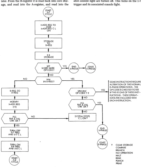
I-Op Cycle (Figure 4)
The I-phase is started when the last execute cycle com-pletion signals the system to end the E-phase and start the I-phase. The first I-phase trigger (I-Op) is turned on and the OP instruction-length light on the 1401
con-sole panel turns on.
The controlling circuitry now determines the starting address of the instruction that will be read out of core storage during this I-phase. If the next sequential in-struction (NSI) in the stored program is used, the I-Add. Reg. already contains the core-storage address of its first character. This address was established dur-ing the previous I-phase. The address in the I-Add. Reg. is transferred to the STAR and the I-Add. Reg. key-light on the 1401 console panel turns on. The STAR lights on the console panel display the core-storage position being addressed (in BCD bit form).
NOTE : If the previous instruction was a branch
in-struction, and a branch was initiated, the core-storage address in the A-Add. Reg. is used. The A-Add. Reg. obtained this address (the I -address of a branch in-struction) during the previous I -phase when the branch instruction was read out of core storage.
The STAR activates the lines that cause the specified core-storage position to read out to the B-register where the contents of that position are displayed in BCD form. This core-storage position contains the operation code of the instruction. From the B-register, the Op-code character:
1. is transferred back into core storage where it is stored in the same position it came from
2. is transferred into the Op-register. During the trans-fer, the character is stripped of the word mark, and a C-bit is added or deleted (depends on original bit configuration) for parity purposes.
The core-storage position specified in the I-Add. Reg. is changed by adding one to it. This is accomplished by reading out the contents of the STAR and adding one to it before reading it back into the I-Add. Reg. The I-Add. Reg. now contains the address of the char-acter that follows the Op-code charchar-acter.
par-TURN ON I-OP TRIG AND I-OP C L
I-ADD REG TO STAR I-ADD REG C L
ON
STORAGE TO B-REG
B-REG TO OP-REG, WOWM (REVERSE C-B
m
MODIFY I-ADD REG
(+ 1)
TURN OFF I-OP TRIG AND I-OP C L
TURN ON 1-1 TRIG AND 1-1CL
Figure 4. I-Op Cycle
NO
A-ADD REG TO STAR A-ADD REG C L
ON
SYSTEM STOPS C L ON*
*Refer to Figure 2 for appropriate lights
ity or validity check will not show up during an I-Op cycle, however.)
If no check condition occurs, the I-Op trigger is
turned off. This turns off the OP instruction length light
on the console panel and turns on the I-I trigger. The
I-I instruction length light on the console panel is then turned on.
1-1 Cycle (Figure 5)
The I-I trigger and its associated I-I instruction-length light tum on when the I-Op trigger turns off. The I-Add. Reg. already contains the core-storage location of the second instruction character. (Actually, the STAR already contains the core-storage location of the second instruction character. This address was transferred from the I-Add. Reg. to the STAR in the last part of the previous I-cycle, but this is not evident during a single-cycle operation.) This address is transferred to the STAR, which then addresses core storage. The charac-ter is read out of storage and into the B-regischarac-ter. From the B-register it is read back into core storage, and is also checked to see if the character has a word mark associated with it (signifying another Op code).
I-CHARACTER INSTRUCTION
Normally, the second character of an instruction is the hundreds-thousands position of an A-field address. If
the character does have a word mark, it means that this character is the Op code for the next instruction. Only one character has been read out of core storage (Op code) so the previous addresses in the A- and B-address registers will be used in the execution of this instruc-tion if this is a chaining type of operation.
The previous Op code (read out during the I-Op cycle) is checked to see if it is one of the Op codes that has to set up the alteration of some of the normal E-phase operations before the actual instruction execu-tion begins. If E-phase alteration is not needed, the Op-register and all other appropriate parity and valid-ity checks are made. Any check condition stops the system and turns ON the appropriate check lights on
the console panel. If no check condition occurs, the I-phase ends and the E-phase begins.
2-CHARACTER INSTRUCTION
If this second character does not have a word mark, it means that the instruction is at least two characters long. It may be only two characters long, but this can-not be established until 1-2 cycle time. Because of this possibility, the character is transferred from the B-reg-ister to the A-regB-reg-ister. The A-regB-reg-ister normally stores the operation modifier character and, in a 2-character instruction, the second character would be the modifier.
OTHER LENGTH INSTRUCTION
Because this might be a longer-length instruction, the character must be stored in the hundreds-thousands position of the A.- and B-Add. Reg. However, for cer-tain operations, the character should be placed in the hundreds-thousands position of the A-Add. Reg. only.
t CLEAR STORAGE COMPARE BRANCH NO OPERA nON HALT READ PUNCH PRINT
NO
!:,~, 9,!::!?
OP REG YES &ALL PAR &
VAL CHK OK?
*REFER TO FIGURE 2 FOR APPROPRIATE LIGHTS
Figure 5. 1-1 Cycle
I-ADD REG TO STAR I-ADD REG C L
ON
STORAGE TO B-REG
The Op code is checked, and if it is an
L.,
M, Q, or H Op code, the character enters the A-Add. Reg. only.If it is not one of these codes, it is placed in the hun-dreds-thousands position of the A-Add. Reg. and B-Add. Reg.
The address in the I-Add. Reg. is increased by one, and the Op-register and all other appropriate parity and validity checks are made. Any check condition stops the system and turns on the appropriate check lights on the console panel. If no check condition oc-curs, the I-I trigger and its associated console light are
YES
SOME INSTRUCTIONS REQUIRE ALTERATION OF THE NORMAL E-PHASE OPERATIONS. THE OP CODE IS CHECKED TO SEE IF THIS IS ONE OF THESE INSTRUCTIoNs. THESE OPERA TlONS ARE INCLUDED WITH EACH INSTRUCTION.
turned off. This turns on the 1-2 trigger and its associ-ated console light.
!-2 Cyde {Fig!J!'e 6}
YES
Figure 6. 1-2 Cycle
I-ADD REG TO STAR I-ADD REG C L
ON
of the previous I-cycle, but this is not evident during a single-cycle operation.) This address is transferred to
the STAR which then addresses core storage. The
char-acter is read out of storage and into the B-register. From the B-register it is read back into core storage and is also checked to see if the character has a word mark associated with it (signifying another Op code).
2-CHARAcrER INSTRUCTION
Normally, the third character of an instruction is the tens-position character of an A-field address. If the character does have a word mark, it means that this character is the Op code for the next instruction. The two characters read out of core storage make up the complete instruction.
YES
>--_Y_ES_-I ~~~~~~~ug~I~~s ~~~:~ ' - _ _ .----_---J E-PHASE OPERATIONS.
THE OP CODE IS CHECK ED TO SEE IF THIS IS ONE OF THESE INSTRUCTIONS. THESE OPERATIONS ARE INCLLDED WITH EACH INSTRUCTION.
YES
t CLEAR STORAGE COMPARE BRANCH NO OPERATION HALT READ PUNCH PRINT
* REFER TO FIGLRE 2 FOR APPROPRIATE LIGHTS
The previous Op code (read out during the I-Op cycle) is checked to see if it is one of the Op codes that has to set up the alteration of the normal E-phase oper-ations before the actual instruction execution begins.
If E-phase alteration is not needed, the appropriate parity and validity checks are made. Any check condi-tion stops the system and turns on the appropriate check lights on the console panel. If no check condition occurs, the I-phase ends and the E-phase begins.
OTHER LENGTH INSTRUCTION
If this third character does not have a word mark, it means that the instruction is at least four characters long (Op code plus one 3-character address). It may be longer, but this cannot be established now.
The character is transferred from the B-register to the A-register, where it replaces the character that was stored there during the I-I cycle. This character could not be an operation modifier character, but it is still stored in the A-register.
Also, the character must be stored in the tens posi-tion of the A- and B-Add. Reg. However, for certain operations, the character should be placed in the tens position of the A-Add. Reg. only. The Op code is checked, and if it is an L, M, Q, or H Op code, the char-acter enters the A-Add. Reg~ onli If it is not one of these codes, it is placed in the tens position of the A-Add. Reg. and B-A-Add. Reg.
The address in the I-Add. Reg. is increased by one, and the appropriate parity and validity checks are made. Any check condition stops the system and turns on the appropriate check lights on the console panel.
If no check condition occurs, the 1-2 trigger and its as-sociated console light are turned off. This turns on the I -3 trigger and its associated console light.
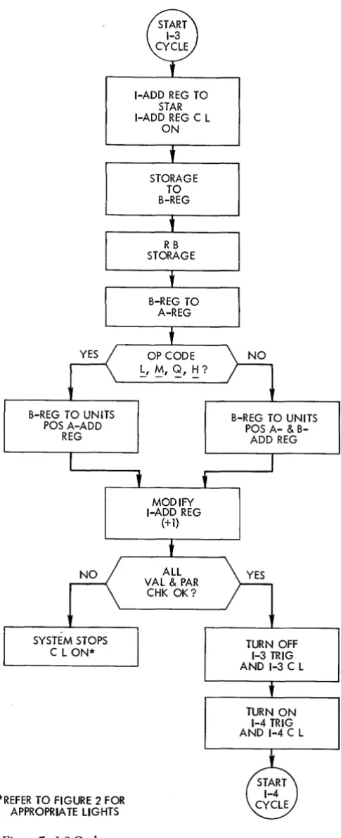
1-3 Cycle (Figure 7)
The 1-3 trigger and its associated instruction-length light are turned on when the 1-2 trigger is turned off. The I-Add. Reg. already contains the core-storage loca-tion of the fourth instrucloca-tion character. (Actually, the STAR already contains the core-storage location of the fourth instruction character. This address was trans-ferred from the I-Add. Reg. to the STAR in the last part of the previous I-cycle, but this is not evident during a single-cycle operation.) This address is transferred to the STAR, which then addresses core storage. The character is read out of storage and into the B-register. From the B-register it is read back into core storage and read into the A-register.
It is possible that this may be the last character of the instruction, but this cannot be established before the next I -cycle. Regardless of the final length, this fourth character must be stored in the units position of the A-Add. Reg. and B-Add. Reg. However, the same conditions present during the I-I and 1-2 cycles are still valid here. The Op code is checked, and if it is an
1,
M,
Q, or H Op code, the character enters the units position~ theA-Add. Reg. only. If it is not one of these Op codes, it is placed in the units position of the A-Add. Reg. and B-Add. Reg.
The address in the I-Add. Reg. is increased by one, and the appropriate parity and validity checks are made. Any check condition stops the system and turns on the appropriate check lights on the console panel.
If no check condition occurs, the 1-3 trigger and its as-sociated console light are turned off. This turns on the I -4 trigger and its associated console light.
10
B-REG TO UN ITS POS A-ADD
REG
SYSTEM STOPS C L ON*
*REFER TO FIGURE 2 FOR APPROPRIATE LIGHTS
Figure 7. I-3 Cycle
1-4 Cycle (Figure 8)
I-ADD REG TO STAR I-ADD REG C L
ON
STORAGE TO B-REG
MODIFY I-ADD REG
(+1)
ALL VAL & PAR
CHK OK?
B-REG TO UNITS POS A-&
B-ADD REG
TURN OFF 1-3 TRIG AND 1-3 C L
TURN ON 1-4 TRIG AND 1-4 C L
[image:10.615.305.548.62.658.2]YES
NO
Figure 8. 1-4 Cycle
I-ADD REG TO STAR I-ADD REG C L
ON
STORAGE
TO
B-REG
MODIFY I-ADD REG
(+l)
TURN OFF 1-4 TRIG AND 1-4 C L
TURN ON 1-5 TRIG AND 1-5 C L
NO
STAR already contains the core-storage locatioIl: of the fifth instruction character. This address was trans-ferred from the I-Add. Reg. to the STAR in the last part of the previous I-cycle, but this is not evident dur-ing a sdur-ingle-cycle operation.) This address is trans-ferred to the STAR, which then addresses core storage. The character is read out of storage and into the B-reg-ister. From the B-register it is read back into core storage.
YES
SOME INSTRUCTIONS REQUIRE AL-TERATION OF THE NORMAL E-PHASE OPERATIONS. THE OP CODE IS CHECKED TO SEE IF THIS IS ONE OF THESE INSTRUCTION. THESE OP-ERATIONS ARE INCLUDED WITH EACH INSTRUCTION.
t CLEAR STORAGE COMPARE BRANCH NO OPERA nON HALT
READ PUNCH PRINT
* REFER TO FIGlRE 2 FOR APPROPRIA TE LIGHTS
BRANCH INSTRUCTION
The Op code stored in the Op-register is checked to see
if it is a B. If it is a ~ then the B-register contents are checked to see if it is a blank character (C-bit only), or whether the character has a word mark associated with it. If either of these conditions are present, it signifies a BHANCH instruction (unconditional). llefer to the BRANCH instruction for the remainder of the operation. If it is still a B Op code, but the B-register contains
[image:11.612.80.525.58.573.2]something else, it signifies a BRANCH IF INDICATOR ON
instruction or a BRANCH IF CHARACI'ER EQUAL
instruc-tion. The B-register then sends this fifth instruction character (the operation-modifier character) to the A-register and the hundreds-thousands position of the B-Add. Reg. (B-Add. Reg. previously reset to blanks). The address in the I-Add. Reg. is increased by one, and the appropriate parity and validity checks are made. Any check condition stops the system, and turns on the appropriate check lights on the console panel.
B-REG TO TENS POS
B-ADD REG
MODIFY I-ADD REG
(+ 1)
TURN OFF 1-5 TRIG AND 1-5 C L
Figure 9. 1-5 Cycle
12
NO
NO
I-ADD REG TO STAR 'I-ADD REG C L
ON
STORAGE TO B-REG
WM iN B-REG?
SYSTEM STOPS
C L ON *
YES
If no check condition occurs, the 1-4 trigger and its as-sociated console light are turned off. This turns on the I -5 trigger and its associated console light.
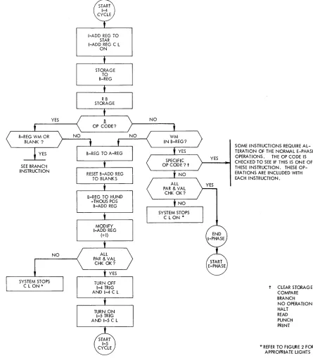
OTHER INSTRUCTION
If the Op code stored in the Op-register is not a
1!,
then the character in the B-register is checked for an asso-ciated word mark. If there is no word mark, then the B-register contents are sent to the A-register and the hundreds-thousands position of the B-Add. Reg.(B-YES
SOME INSTRUCTIONS REQUIRE ALTERATION OF THE NORMAL E-PHASE OPERATIONS. THE OP CODE IS CHECKED TO } - - - -... SEE IF THIS IS ONE OF THESE
YES
INSTRUCTIONS. THESE OPERATIONS ARE INCLUDED
WITH EACH INSTRUCTION,
t CLEAR STORAGE COMPARE BRANCH NO OPERATION HALT
READ PUNCH PRINT
[image:12.613.51.539.197.711.2]Add. Reg. previously reset to blanks). The I-Add. Reg. modification, the parity and validity checking, and the I-cycle progression previously described now occur.
If there is a word mark in the B-register (signifying a new Op code), then the Op code read out during the I -Op cycle is checked to see if it is one of the Op codes that has to set up the alteration of the normal E-phase operations before the actual instruction execution be-gins. If E-phase alteration is not needed, the appropri-ate parity and validity checks are made. Any check condition stops the system and turns on the appropriate check lights on the console panel. If no check condition occurs, the I-phase ends and the E-phase begins.
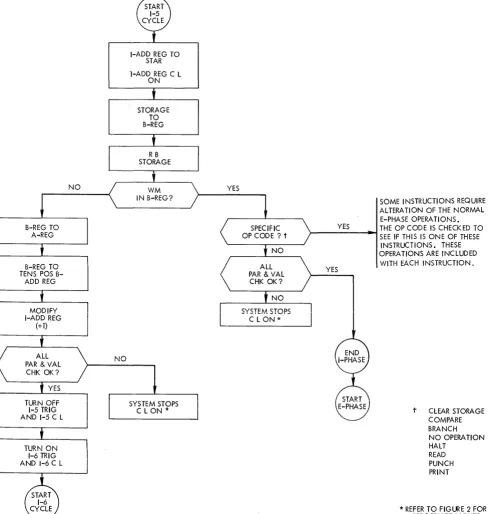
1-5 Cycle (Figure 9)
The 1-5 trigger and its associated instruction-length light are turned on when the 1-4 trigger is turned off. The I-Add. Reg. already contains the core-storage loca-tion of the sixth instrucloca-tion character. (Actually, the STAR already contains the core-storage location of the sixth instruction character. This address was transferred from the I-Add. Reg. to the STAR in the last part of the previous I-cycle, but this is not evident during a single-cycle operation.) This address is transferred to the STAR, which then addresses core storage. The charac-ter is read out of storage and into the B-regischarac-ter. From the B-register it is read back into core storage, and the character is also checked to see if it has a word mark associated with it (signifying another Op code).
5-CHARACfER INSTRUCTION
If the character has a word mark associated with it, then the five preceding characters constitute a com-plete instruction (Op code, a 3-character address, and an operation-modifier character). The Op code read out during the I -Op cycle is checked to see if it is one of the Op codes that has to set up the alteration of the normal E-phase operations before the actual instruction execu-tion begins. If E-phase alteration is not needed, the appropriate parity and validity checks are made. Any check condition stops the system and turns on the ap-propriate check lights on the console panel. If no check condition occurs, the I-phase ends and the E-phase begins.
OTHER INSTRUCTION
If the character does not have a word mark associated with it, then the B-register contents are sent to the A-register and the tens position of the B-Add. Reg.
The address in the I-Add. Reg. is increased by one, and the appropriate parity and validity checks are made. Any check condition stops the system and turns on the appropriate check lights on the console panel.
If no check condition occurs, the 1-5 trigger and its as-sociated console light are turned off. This turns on the 1-6 trigger and its associated console light.
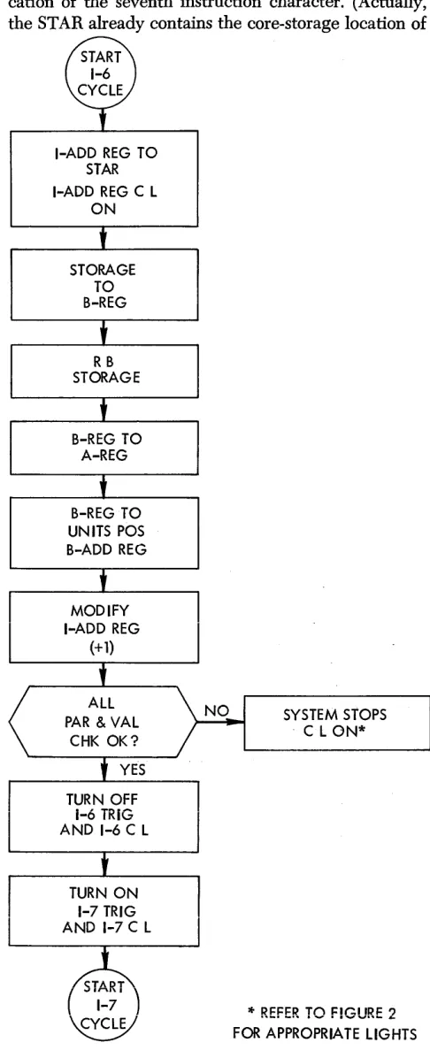
1-6 Cycle (Figure 10)
The 1-6 trigger and its associated instruction-length light are turned on when the 1-5 trigger is turned off. The I-Add. Reg. already contains the core-storage lo-cation of the seventh instruction character. (Actually, the STAR already contains the core-storage location of
I-ADD REG TO STAR I-ADD REG C L
ON
STORAGE TO B-REG
RB STORAGE
B-REG TO A-REG
B-REG TO UNITS POS B-ADD REG
MODIFY I-ADD REG
(+ 1)
TURN OFF i-6 TRIG AND 1-6 C L
(£)
1-7 [image:13.612.325.568.124.722.2]~
Figure 10. 1-6 Cycle
SYSTEM STOPS . C L ON*
*
REFER TO F!GURE 2FOR APPROPRIATE LIGHTS
the seventh instruction character. This address was transferred from the I-Add. Reg. to the STAR in the last part of the previous I-cycle, but this is not evident during a single-cycle operation.) This address is trans-ferred to the STAR, which then addresses core storage. The character is read out of storage and into the B-reg-ister. From the B-register it is read back into core stor-age, and read into the A-register, and read into the
MODIFY I-ADD REG
(+1)
TURN OFF 1-7 TRIG AND 1-7 C L
[image:14.615.43.538.150.735.2]TURN ON 1-8 TRIG AND 1-8 C L
Figure 11. 1-7 Cycle
NO
NO
I-ADD REG TO STAR I-ADR REG C L
ON
STORAGE TO B-REG
units position of the B-Add. Reg.
The address in the I -Add. Reg. is increased by one, and the appropriate parity and validity checks are made. Any check condition stops the system and turns on the appropriate check lights on the console panel. If
no check condition occurs, the 1-6 trigger and its associ-ated console light are turned off. This turns on the 1-7 trigger and its associated console light.
YES
SOME INSTRUCTIONS REQUIRE ALTERATION OF THE NORMAL E-PHASEOPERATIONS. THE OPCODE ISCHECKEDTOSEE
)----~ IF THIS IS ONE OF THESE
INST-6
~
tE~~~!E)
V
*REFER TO FIGURE
RUCTIONS. THESE OPERAT-IONSARE INCLUDED WITH EACH INSTRUCTION.
t CLEAR STORAGE COMPARE BRANCH NO OPERATION HALT
READ PUNCH PRINT
1-7 Cycle (Figure 11)
The 1-7 trigger and its associated instruction-length light are turned on when the 1-6 trigger is turned off. The I-Add. Reg. already contains the core-storage loca-tion of the eighth instrucloca-tion character. (Actually, the STAR already contains the core-storage location of the eighth instruction character. The address was trans-ferred from the I-Add. Reg. to the STAR in the last part of the previous I -cycle, but this is not evident dur-ing a sdur-ingle-cycle operation.) This address is trans-ferred to the STAR, which then addresses core storage. The character is read out of storage and into the B-reg-ister. From the B-register it is read back into core storage.
SET WORD MARK INSTRUCTION
The Op code stored in the Op-register is checked to see if it is a set word mark Op code. If it is, the I-phase ends and the E-phase begins. This is done so that word marks can be set in specified core-storage locations dur-ing the program-loaddur-ing routine.
If the Op code stored in the Op-register is not a set
word mark Op code, then the B-register character is checked to see if it has a word mark associated with it (signifying another Op code).
7 -CHARACTER INSTRUCTION
If the character has a word mark associated with it, then the seven preceding characters constitute a com-plete instruction (Op code and two 3-character ad-dresses). The Op code read out during the I-Op cycle is checked to see if it is one of the Op codes that has to set up alteration of some of the normal E-phase operations before the actual instruction execution begins. If E-phase alteration is not needed, the appropriate parity and validity checks are made. Any check condition stops the system and turns on the appropriate check lights on the console panel. If no check conditions occur, the I-phase ends and the E-phase begins.
OTHER INSTRUCTION
If the character does not have a word mark associated with it, then the character must be an operation-modi-fier character, and the B-register contents are sent to the A-register.
The address in the I-Add. Reg. is increased by one, and the appropriate parity and validity checks are made. Any check condition stops the system and turns on the appropriate check lights on the console panel. If
no check condition occurs, the 1-7 trigger and its associ-ated console light are turned off. This turns on the 1-8 trigger and its associated console light.
1-8 Cyde (Fi;;;re 12)
The 1-8- trigger and its associated instruction-length light are turned on when the 1-7 trigger is turned off.
The I.Add. Reg. already contains the core-storage loca-tion of the next character, which should be the Op-code character of the next instruction. (Actually, the STAR already contains this core-storage location. The address was transferred from the I-Add. Reg. to the STAR in the last part of the previous I-cycle, but this is not evi-dent during a single-cycle operation.) This address is transferred to the STAR, which then addresses core storage. The character is read out of storage and into the B-register. From the B-register it is read back into core storage. The character is also checked to see if it has a word mark associated with it (signifying another Op code).
8-CHARACTER INSTRUCTION
If the character has a word mark associated with it, then the eight preceding characters institute a complete instruction (Op code, two 3-character addresses, and an operation-modifier character). The Op code read out during the I -Op cycle is checked to see if it is one of the Op codes that has to set up alteration of some of the normal E-phase operations before the actual instruc-tion execuinstruc-tion begins. If E-phase alteration is not needed, the appropriate parity and validity checks are made. Any check condition stops the system and turns on the appropriate check lights on the console panel. If
no check conditions occur, the I-phase ends and the E-phase begins.
PROGRAMMING ERROR
If the character does not have a word mark associated with it, then the B-register contents are sent to the A-register. The address in the I-Add. Reg. is increased by one, and the appropriate parity and validity checks are made. Any check condition stops the system and turns on the appropriate check lights on the console panel. If
no check condition occurs, then the 1-8 cycle is repeated until a character with a word mark is read out of core storage. This condition signifies poor programming technique because the program has gaps between se-quential instructions.
Instruction Execution (E-Phase)
Normally, the word mark associated with the Op code of the next instruction signals the end of the I-phase. Ending the I-phase automatically starts the E-(execute) phase.
The E-phase is the system operating time necessary to perform the operation specified by the instruction read out during I-phase. The E-phase is made up of A-cycles and/or B-cycles. During an A-cycle, one position of data from the previously-specified A-field is read out of core storage. During a B-cycle, one position of data from the previously-specified B-field is read out of core storage.
MODIFY I-ADD REG
(+ 1)
Figure 12. 1-8 Cycle
NO
A-Cycle (Figure 13)
NO
I-ADD REG TO STAR I-ADD REG C L
ON
STORAGE TO B-REG
The first cycle during any E-phase is usually an A-cycle (some instructions have no A-cycles). The A-cycle illus-trated in Figure 13 is an A-cycle operation that is com-mon to many 1401 instructions. When discussing in-structions that use the common A-cycle, reference is made to Figure 13. A-cycles that are different are cov-ered in that instruction writeup.
The A-Add. Reg. contains the core-storage location specified in the A-address portion of the previously-read instruction. This core-storage location is, normally, the units position of the field. The address in the A-Add. Reg. is transferred to the STAR, and the A-A-Add. Reg. key-light on the 1401 console panel is turned on. The STAR lights on the console panel display the
core-YES
SOME INSTRUCTIONS RE-QUIRE ALTERATION OF THE NORMAL E-PHASE OPERA-TIONS. THE OP CODE IS CHECKED TO SEE IF THIS IS ONE OF THESE INSTRUC-TIONS. THESE OPERATIONS ARE INCLUDED WITH EACH INSTRUCTION.
t CLEAR STORAGE COMPARE BRANCH NO OPERA liON HALT
READ PUNCH PRINT
*REFER TO FIGURE 2 FOR APPROPRIATE LIGHTS
storage position being addressed (in BCD bit form). The STAR activates the lines that cause the specified core-storage position to read out to the B-register where the contents of that position are displayed in BCD fonll. From the B-register, it is normally read back into the core-storage position it came from, and it is also trans-ferred to the A-register where it is displayed in BCD
r
rorm.
A-ADD REG TO STAR A-ADD REG C L
ON
STORAGE TO B-REG
MODIFY A-ADD REG
(-l)
Figure 13. A-Cycle
SYSTEM STOPS
C LONoiC
* REFER TO FIGURE 2 FOR APPROPRIATE LIGHTS
first, followed by the tens digit, etc. Therefore, the ad-dress in the A-Add. Reg. must be modified by -1 each time so that the adjacent lower-numbered location is read out. This -1 modification is accomplished by reading out the contents of the STAR and subtracting one from it before reading it back into the A-Add. Reg. The parity and validity checks are made. Any check condition stops the system and turns on the appropriate check lights on the console panel.
If no check condition occurs, the A-cycle ends and the B-cycle begins (the STORE ADDRESS REGISTER instruc-tions are excepinstruc-tions).
B-Cycle
It is during the B-cycle that the instruction execution usually takes place. In an add operation, for instance, the actual addition of the A- and B-field characters takes place during the B-cycle and the result is stored
in the B-field position. Therefore, all instructions dis-cussed in this publication normally show the system's method of operation during a B-cycle. However, when the A-cycles differ from the common A-cycle, this dif-ference is discussed along with any other forms of in-struction execution that may be used.
E-Phase Termination
The E-phase portion of an instruction is usually ended when a word mark is sensed in the B-register. The word mark signifies that the end of that word in core storage has been reached. However, there are opera-tions that stop only when an A-field word mark is sensed. Other operations stop only when a B-field word mark is sensed, and still other operations stop when either an A-field or a B-field word mark is sensed. These different conditions are all included in the system's in-ternal circuitry and the actual operation termination is done automatically.
Logic Operations
Branch (§ "')
The BRANCH (unconditional) instruction
(!!
III) alwayscauses the program to branch to the specified I-address. This address contains the Op code of some instruction. This branch operation is used to interrupt normal pro-gram sequence, and to continue the propro-gram at some other desired point, without testing for any specific conditions.
I-Phase Operation (Figures 8 and 14)
During 1-4 time of an I-phase, the Op-register is checked to see if it contains a B Op code. When a
1!
Op code is established, the B-register is checked to see if it contains a blank character or a word mark (the Op-code position of the next sequential instruction). When one of these two conditions is established, the circuitry to eliminate the E-phase portion of this instruction is a\)-tivated.~ OP CODE AT 1-4 TIME B-REG WM OR BLANK?
YES
ELIMINATE E-PHASE
BLOCK I-ADD REG RO DURING
I-OP TIME
ALLOW A-ADD REG RO DURING
I-OP TIME
TURN OFF 1-4 TRIG AND 1-4 C L
TURN ON
i-OP TRiG
AND OP C L
SYSTEM STOPS C L ONoJc
* REFER TO FIGURE 2 FOR APPROPRIATE LIGHTS
Figure 14. Branch Instruction I-Phase Operation
Also, circuitry is activated that blocks the I-Add. Reg. read-out, and allows the A-Add. Reg. read-out during the next I-Op cycle. (The A-Add. Reg. contains the I-address as specified by the instruction.)
The appropriate parity and validity checks are made. Any check condition stops the system and turns on the appropriate check lights on the console panel. If no check condition occurs, the 1-4 trigger and its associated console light are turned off. This turns on the I-Op trigger and its associated console light. During the I-Op cycle, the core-storage position specified by the I-ad-dress (in the A-Add. Reg.) is read out of core storage, followed by a normal I-phase operation.
Branch if 'ndicator On (§ "' d)
The BRANCH IF INDICATOR ON instruction (~ III d) causes
the program to branch to the specified I -address if the specified indicator, when tested, is on. If the indicator is off, the next sequential instruction is read.
I-Phase Operation (Figures 9 and 15)
During 1-5 time of an I-phase, the B-register is checked to see if it contains a word mark. If the B-register does contain a word mark (the Op-code position of the next sequential instruction), the Op-register is checked to see if it contains a B.
When the presence of a. B Op code is established, the circuitry to eliminate the E-phase portion of this in-struction is activated.
The indicator specified by the operation-modifier character (d-character) is tested to see if it is on. If the indicatoi is on, crrcuitiY is activated that blocks the I-Add. Reg. out, and allows the A-Add. Reg. read-out during the next I-Op cycle. (The A-Add. Reg. con-tains the I -address as specified by the instruction.) If
the indicator is not on, the normal I-Add. Reg. read-out is active during the next I-cycle.
B-REG WM B OP CODE?
YES
ELIMINATE E-PHASE
BLOCK I-ADD REG RO DURING
i-oP TIME
ALLOW A-ADD REG RO DURING
I-OP TIME
TURN OFF 1-5 TRIG AND 1-5 C L
TURN ON I-OP TRIG AND OP C L
NO NO
I-ADD REG READS OUT DUR-JNG J-OP TIME
SYSTEM STOPS C LONoJ¢
oJ¢REFER TO FIGURE 2 FOR APPROPRIATE LIGHTS
Figure 15. Branch if Indicator On Instruction: I-Phase Operation
Branch if
Character Equal(l! '"
SSS d)
Branch if
Word Markand/ or Zone
(¥.'"
88Bd)
Both the BRANCH IF CHARACTER EQUAL instruction (~ III
BBB d) and the BRANCH IF WORD MARK AND/OR ZONE
instruction (Y III BBB d) cause the program to branch to the specified I-address if the condition specified by the operation-modifier character (d-character) is met by the character located in the specified B-address. The
BR.<\NCH IF CILt\ .. !L':\'CT1<'~ EQU.A~L instruction tests the
char-acter at the B-address for the same bit configuration as the d-character, and branches if the bit configuration is
d-character Condition
1 Word mark
2 No zone (No-A, No-B-bit)
B 12-zone (AB-b its)
K ll-zone (B, No-A-b it)
S Zero-zone (A, No-B-bit)
3 Either a word mark, or no zone C Either a word mark, or 12-zone L Either a word mark, or 1l-zone T Either a word mark, or zero-zone
Figure 16. Branch if Word Mark and/or Zone d-Characters and
Conditions
the same. The BRANCH IF WORD MARK AND/OR ZONE
in-struction tests the character at the B-address for the condition specified by the d-character, and branches if the condition is met. The d-characters and the condi-tions they represent are shown in Figure 16.
I-Phase Set-Up Operations (Figure 17)
Some instructions require alterations of the normal E-phase operations for correct execution of the instruc-tion. These alterations are set up before the I-phase ends. During certain I-cycles the Op code is checked to see if it is one of the Op codes that has to set up the alteration of the normal E-phase operations before the actual instruction execution begins. As soon as the word mark is sensed in the B-register, either a B or V Op code sets up the circuitry to eliminate A-cycles and exe-cute one B-cycle. The appropriate parity and validity checks are made: Any check condition stops the system and turns on the appropriate check lights on the con-sole panel. If no check condition occurs, the I-phase ends and the E-phase begins.
Single B-Cycle (Figure 17)
The core-storage position containing the character that is checked by the d-character during this single B-cycle was previously specified by the instruction, and the ad-dress was placed in the B-Add. Reg. during I-phase. The address in the B-Add. Reg. is transferred to the STAR and the B-Add. Reg. key-light on the console panel is turned on. The STAR lights on the console panel display the core-storage position being addressed (in BCD form).
The STAR activates the lines that cause the specified core-storage position to read out to the R .. register, where the contents of that position are displayed in BCD form.
The character in the B-register is read back into the core-storage position it came from. The Op code is then checked to see if it is a B or a
y
Op code.!! OP CODE
If it is a B Op code, then the A-register contents (the d-character) are compared against the B-register
B-ADD REG TO STAR B-ADD REG C L
ON
* REFER TO FIGURE 2 FOR APPROPRIATE LIGHTS
SYSTEM STOPS C L ON*
Fig-ure 17. Branch if Character Equal and Branch if \Vord Mark and/or Zone Instructions: 1- and E-Phase Operations
tents (the B-field character). If the bit configurations are the same, the branch to the specified I -address oc-curs. The circuitry is activated that blocks the I-Add. Reg. read-out, and allows the A-Add. Reg. read-out during the next I-Op cycle. (The A-Add. Reg. contains the I -address as specified by the instruction.) If the bit
configurations are not the same, the normal I-Add. Reg. read-out is active during the next I-Op cycle.
YOPCODE
If the Op code is a
y
Op code, then the B-register con-tents (the B-field character) is checked to see if the bits specified by the A-register contents (the d-character) are present. If the specified bits are present, the branch to the specified I-address occurs. The circuitry is acti-vated that blocks the I-Add. Reg. read-out, and allows the A-Add. Reg. read-out during the next I-Op cycle. (The A-Add. Reg. contains the I-address as specified by the instruction.)If the specified bits are not present, the normal I-Add. Reg. read-out is active during the next I-Op cycle.
The appropriate parity and validity checks are made. Any check condition stops the system and turns on the appropriate check lights on the console panel. If no check condition occurs, the E-phase ends and I-phase begins.
No
Operation (N)
An instruction with an N Op code performs no opera-tion. It can be substituted for the operation code of any instruction to make that instruction ineffective. It is commonly used in program modification to cause the program to skip over a specific instruction. This in-struction skipping is accomplished by eliminating the E-phase. The instruction reading continues until the word mark of the next instruction is sensed. If charac-ters without word marks follow an N Op code, these characters enter the A- and B-address registers.
I-Phase Operation (Figure 18)
During I-phase, a word mark in ~~e B-register signals the end of I-phase and the beginning of E-phase. Dur-ing certain I -cycles, the Op code is checked to see if
any special operations must be performed before 1-phase ends.
If the Op code is an ~ circuitry is set up to eliminate the E-phase portion of the operations. Then the appro-priate parity and validity checks are made. Any check condition stops the system and turns on the appropriate check lights on the console panel. If no check condition occurs, the I-trigger and the associated console light that are on are turned off. The I-Op trigger and its asso-ciated console light are turned on and an I-Op cycle begins.
Compare (C AAA SSS)
The COMPARE instruction compares the data in the
ELIMINATE E-PHASE
TURN OFF
1-TRIGGER AND ASSOCIATED C L
TURN ON I-OP TRIG AND OP
CL
SYSTEM STOPS C L ON*
*REFER TO FIG~E 2 FOR APPROPRIATE LIGHTS
Figure 18. No Operation Instruction: I-Phase Operation
The bit configuration of each character in the two fields is compared and the comparison lets the equal-compare latch stay on, or it turns the latch off. The latch setting can be tested by a BRANCH IF INDICATOR ON instruction.
This latch is initially set ON during 1-2 time (not shown
in Figure 6).
I-Phase Set-Up Operations (Figure 19)
Some instructions require alterations of the normal E-phase operations for correct execution of the instruc-tion. These alterations are set up before the I-phase ends. During certain I -cycles the Op code is checked to see if it is one of the Op codes that has to set up the alteration of the normal E-phase operations before the actual instruction execution begins. As soon as a wOl:d mark is sensed in the B-register, the appropriate parity and validity checks are made. Any check condition stops the system and turns on the appropriate check lights on the console panel. If no check condition oc-curs, the I-phase ends and the E-phase begins. The first cycle executed during the E-phase is an A-cycle. The common A-cycle previously described (see Figure 13 and the accompanying text) is used during the A-cycle portion of the E-phase. As soon as the A-cycle is suc-cessfully completed, the B-cycle begins.
B-Cycle (Figure 19)
The core-storage position containing the B-field char-acter compared by the A-field charchar-acter during this B-cycle was previously specified by the instruction, and the address was placed in the B-Add. Reg. during 1-phase. The address in the B-Add. Reg. is transferred to the STAR and the B-Add. Reg. key-light on the console panel is turned on. The STAR lights on the console panel display the core-storage position being addressed (in BCD form).
The STAR activates the lines that cause the specified core-storage position to read out to the B-register, where the contents of that position are displayed in BCD form.
The character in the B-register is read back into the core-storage position from which it came. The address in the B-Add. Reg. is decreased by one, and the appro-priate parity and validity checks are made. Any check condition stops the system and turns on the appropriate check lights on the console panel. If no check condition occurs, the A-field character bit configuration is com-pared against the B-field character bit configuration.
If the character comparison results in an unequal condition, the equal-compare latch, which was turned on during the I-phase, is turned off. The latch remains on if the characters are equal.
The B-register is then checked to see if it contains a word mark. If a word mark is present, the E-phase ends and the I-phase for the next instruction begins.
If no word mark is present in the B-register, then the A-register is checked to see if it contains a word mark.
If no word mark is present in the A-register, then the compare operation is continued and another A-cycle is started. If a word mark is present in the A-register, it signifies the presence of a B-field that is longer than the A-field and it results in an unequal condition. The equal-compare latch is turned off, followed by the end-ing of the E-phase and the startend-ing of the I-phase for the next instruction.
Halt (.!.J
Halt and Branch (.!.II')
Both the HALT instruction (!) and the HALT AND BRANCH
instruction (!. III) cause a system stop, and tum on the stop key-light on the 1401 console panel.
If the instruction is a HALT instruction only,
operat-ing the start key causes the program to start at the next instruction in sequence.
If the instruction is a IIALT A~ID BP..ANCH instruction,
operating the start key causes the program to start at the specified I-address.
COMPARE OP CODE C
SEE FIGURE 13 FOR COMMON
A-CYCLE
SYSTEM STOPS C L ON*
COMPARE INSTRUCTION SET-UP OPERATIONS COMPLETED DURING I-PHASE
E-PHASE AND A-CYCLE START
*REFER TO FIGURE 2 FOR APPROPRIATE LIGHTS
Figure 19. Compare Instmction: 1- and E-Phase Operation
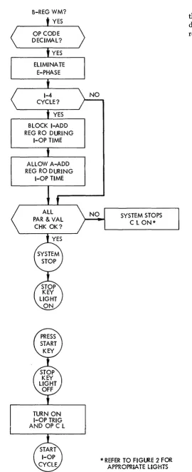
I-Phase Operation (Figure 20)
During the I-phase cycle that has a word mark in the B-register, the Op-register is checked to see if it con-tains a decimal. When the presence of a decimal Op code is established, the circuitry that eliminates the E-phase portion of this instruction is activated.
The present I-phase cycle must be determined. If the I -phase cycle is 1-4, circuitry is activated that blocks the I-Add. Reg. read-out, and allows the A-Add. Reg. read-out during the next I-Op cycle. (The A-Add. Reg. contains the I -address as specified by the instruction.)
B-ADD REG TO STAR B-ADD REG C L
ON
STORAGE TO B-REG
MODIFY B-ADD REG
(-1)
YES
SYSTEM STOPS C L ON*
If the I-phase cycle is not 1-4, the normal I-Add. Reg. read-out is active during the next I-cycle.
The appropriate parity and validity checks are made. Any check condition stops the system and turns on the appropriate check lights on the console panel. If no check condition occurs, the circuitry that stops the sys-tem is activated and the stop key-light on the 1401 con-sole panel turns on.
ELIMINATE E-PHASE
BLOCK I-ADD REG RO DURING
I-OP TIME
ALLOW A-ADD REG RO DURING
I-OP TIME
TURN ON I-OP TRIG AND OP C L
NO SYSTEM STOPS C L ON*
* REFER TO FIGURE 2 FOR APPROPRIATE LIGHTS
[image:23.615.63.334.46.709.2]the core-storage position specified by either the I-ad-dress (in the A-Add. Reg.), or the I-Add. Reg. will be read out of core storage during this I-Op cycle.
Figure 20. Halt and Halt and Branch Instructions: I-Phase Operation
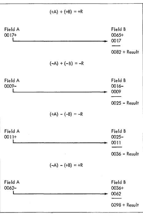
Arithmetic Operations
The add, subtract, zero and add, and zero and subtract operation codes are used to perform the system's arith-metic operations~ The use of add-to-storage logic in the mM 1401 eliminates the need for special-purpose accu-mulators or counters in the system. Because any group of storage positions can be used as an accumulating field, the capacity for arithmetic functions is not limited by a predetermined number of counter positions.
BCD CODE BIT CARD CODE
SIGN
CONFIGURATION CONFIGURA TlON
I
Plus No A- or B-bit No-Zone
Plus A- and B-bits 12-Zone
Minus B-bit only ll-Zone
Plus A-bit only O-Zone
Figure 21. Sign Bit Equivalents
All arithmetic operations are performed under com-plete algebraic sign control. Figure 21 shows the four possible combinations of zone bits and the values of the signs they represent. When the system signs a field, it is done in the standard form. A positive factor is indicated with an A- and a B-bit, and a negative factor is indi-cated with a B-bit. The sign of the resultant field is determined by the type of operation and the signs and values of the data fields as shown in Figure 22.
TYPE OF OPERe A D D S U B T R A C T +
-A-FLD. B-FLD.
SIGN SIGN
+ +
-+ -+ + +TYPE OF ADD SIGN OF
CYCLE RESULT
True add +
Compl. add Sign of greater
value
Compl. add (Standard Form)
True add
-True add
-Compl. add Sign of greater
value
Figure 22. Types of Add Cycles and Sign of Result for Add and Subtract Operation
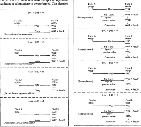
Add (A AAA BBS) and Subtract (§.AAA BBS)
The add and subtract operations in the mM 1401 Data Processing System are performed by using one of the two types of add operations incorporated in the system:
l. true add
2. complement add
The type of add operation that will be taken is deter-mined during the first E-phase B-cycle.
First A-Cycle
The first cycle during any E-phase is always an A-cycle. The A-Add. Reg. contains the core-storage location specified in the A-address portion of the previously-read instruction. In this instance, it is the units position of the A-field. The address in the A-Add. Reg. is trans-ferred to the STAR, and the A-Add. Reg. key-light on the 1401 console panel turns on. The STAR lights on the console panel display the core-storage position being addressed (in BCD form).
The STAR activates the lines that cause the specified core-storage position to read out to the B-register, where the contents of that position are displayed in BCD form. The B-register contents are then read back into the core-storage position they came from, and are also transferred to the A-register. The address in the STAR is transferred back into the A-Add. Reg. without modification. The A-cycle ends and the B-cycle begins.
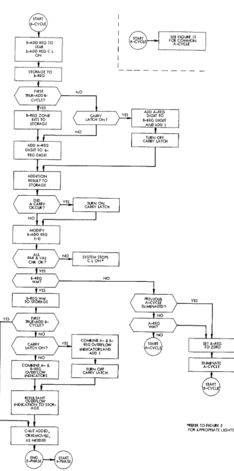
First B-Cycle (Figure 23)
The core-storage position that is the units position of the B-field was previously specified by the instruction, and the address was placed in the B-Add. Reg. during I-phase. The address in the B-Add. Reg. is transferred to the STAR and the B-Add. Reg. key-light on the con-sole panel is turned on. The STAR lights on the concon-sole panel display the core-storage position being addressed (in BCD form).
The STAR activates the lines that cause the specified core-storage position to read out to the B-register, where the contents of that position are displayed in BCD form.
The digit portion of the B-register contents is read back into the core-storage position from which it came. Also, a C-bit is added or removed to maintain odd-bit parity. The address in the STAR is transferred back into the B-Add. Reg. without modification, and the ap-propriate parity and validity checks are made. Any check condition stops the system and turns on the ap-propriate check lights on the console panel. If no check condition occurs the A-register sign is compared against the B-register sign. The result of this comparison, in conjunction with the specified operation, determines the type of add operation performed, and determines the initial sign of the result field.
EQUAL SIGNS
main-FIRST A-CYCLE
YES
OP CODE
C-BIT ADDED, OR REMOVED,
[image:25.615.80.573.54.683.2]AS NEEDED
Figure 23. First A- and B-Cycle During an Add or Subtract Operation S
B-ADD REG TO STAR B-ADD REG C L
ON
A-REG SIGN EQUALS
B-REG SIGN?
FIRST B- CYCLE
NO
SYSTEM STOPS C L ON*
B-REG SIGN TO STORAGE
IN SF
C-B IT ADD ED , OR REMOVED, AS NEEDED
START COMPLEMENT ADD OPERATION
* REFER TO FIGURE 2 FOR APPROPRIATE
LIGHTS
tain odd-bit parity. In this instance, the sign returned to storage is the sign of the resultant B-field (refer to Figure 22). The circuitry used to execute true-add oper-ations is also activated, and the first A-cycle of the true-add operation starts when the B-cycle ends.
If the A-register sign is equal to the B-register sign, and the Op code is ..§. (subtract), then the B-register sign is read back in standard form into the core-storage position it came from and a C-bit is added or removed to maintain odd-bit parity. Depending on the value of the fields involved, this sign may, or may not, be the sign of the resultant B-field (refer to Figure 22). The circuitry used for executin