2017 2nd International Conference on Computer, Mechatronics and Electronic Engineering (CMEE 2017) ISBN: 978-1-60595-532-2
Model Driven Development of Order Management Module for Software
Visual Automation Service
Jian-bin LIU
1and Yuan-yuan JIA
21
School of Computer, Beijing Information Science & Technology University, Beijing 100101, China
2
School of Computer, Beijing Information Science & Technology University, Beijing 100101, China
Keywords: Model-Driven architecture, Computation platform independent model, Process
blueprint.
Abstract. This paper studies the application of model driven development technology in the development of order management module of visual automatic service. In view of the disadvantages of traditional software, such as low productivity, poor portability and difficult maintenance to the system, Model Driven Architecture (MDA) emerges as the times require. MDA can well overcome the drawbacks of the traditional software development described above. Platform, Independent, Model, Platform, Specific, Model, and code are the core of MDA. The method uses the use case diagram, class diagram and process blueprint of UML as the modeling language for the analysis and design of the system. This approach provides the basis for creating and transforming models in the system and generating code. The development experience shows that the model driven development technology adopted in this paper can effectively improve the efficiency of development and improve the system's maintainability and other major quality characteristics.
Introduction
With the upgrading of IT technology and the diversification of enterprise demand, an enterprise will meet more opportunities and challenges, and the integration needs of various software systems will become more and more urgent and intense. MDA (Model Drive Architecture) is a software development framework defined by Object Management Group (OMG). It can drive the design of the whole software development process through the conversion of the model, which makes the application designed more lightweight, compact and easy to operate.
Software visual automation, also called programming thinking visualization, automatically converts the program source code uploaded by users into Chinese text oriented programming thinking maps through the industry leading model and language driven reverse software engineering technology, code scanning analysis and intelligent modeling technology, natural action pattern language construction, translation technology, program model automatic transformation technology. It provides teachers, students and users with making programming thinking teaching resources development, code reading, project development document preparation, experimental report writing, academic degree thesis writing and other related programming model material efficient method.
Model Driven Development Technology
Model Driven Development Framework
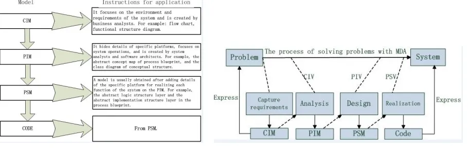
mapping rules are formulated for the system. According to these mapping rules, PIM is transformed into PSM related to implementation technology. Finally, the system is converted to CODE running on a particular platform. Figure 1 shows a contrast between the model and the application.
[image:2.612.82.537.112.259.2]
Figure 1. Model and description of its application. Figure 2. The process of developing a MDA based system.
As Figure 2 shows, the traditional code centric development process lacks clear and well-defined functionality and interface descriptions, so it takes a lot of time and effort for users to understand these functions and interfaces. Moreover, when the system functionality needs to be changed, because of the lack of abstract models, all operations must be carried out on the source code, which is very detrimental to system maintenance and extension.
Model Driven Development Method
The software visual automation technology service system adopts the model driven development method which combines UML (Unified Modeling Language) and process blueprint.
UML is known as the unified modeling language or standard modeling language, which began in 1997 with a OMG standard. It is a software development language that supports modeling and graphical programming. It provides model and visual support for all phases of software development, ranging from requirements analysis to specifications, to construction, and finally to configuration.
Process blueprint is an integrated modeling language that conforms to MDA standards and specifications, and describes processes in a visual and hierarchical manner. It has Abstract Concept Structure Diagram (ACSD), Abstract Logic Structure Diagram (ALSD) [8], Abstract Implementation Structure Diagram (AISD) three layer Abstract external view, corresponding program in concept, logic and the realization of the three level of abstraction models.
Analysis of System Functions
Analysis of Requirements
The task of analyzing requirements is to fully understand the work of the system and identify the needs of the users through detailed investigation of the objects to be processed by the real world. Then, on this basis, the functions of the new system are determined. The new system must take full account of possible expansion and change in the future [9].
In the analysis of requirements, the most important thing is to understand the specific requirements of users and the performance requirements of the system.
A. Analysis requirements of user
B. Analysis of the needs of ordinary administrators C. Ananalysis of the needs of super administrators
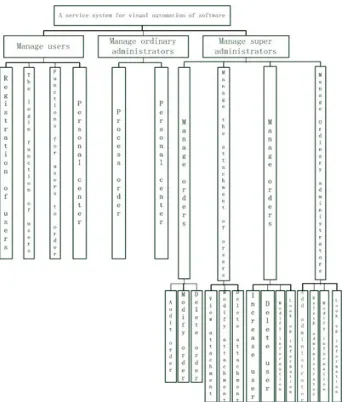
The Design of the Functional Structure of the System
Figure 3. Diagram of the overall architecture of the system. Figure 4. The process of ordering.
Development of Models for CIM, PIM, AND PSM
Development of the CIM Model
The development of CIM model is to construct the model of function and requirement analysis, and introduce the construction process of CIM model with the example of single order module When the user applies for the service, the system will judge whether the user has already logged in first, if the user has not logged in, the system will give the prompt which needs the user to log on the system. After the user log on the system, they can fill in the corresponding information and submit the uploaded document according to the requirement. The procedure for placing this order is shown in Figure 4.
Design of PIM Model
The class diagram in UML describes a static relationship. It is effective throughout the life cycle of the system. Class diagrams define not only the class in the system, but also the relation between classes, such as association, dependency, aggregation, and the internal structure of the class (the attributes and operations of the class). In the static mechanism of UML, class diagram is an important point. In the design process of PIM, the static structure of the system is modeled by the concept class diagram model. Take the module of placing an order for example, the conceptual structure model of class diagram is shown in Figure 5.
class serv let
CheckAction - email
- newpass - password - tag = 0 - username + Activatex() + ChangePassword()
+ createSimpleMail(session, user, email, code, rol e) + GetPersonContact()
+ getUserBySessi on() + LoadUser() + Login() + Logout() + Regi ster() + ReRegister()
+ sendEmail(user, email , code, role) + UpdatePersonInfo() + Upload()
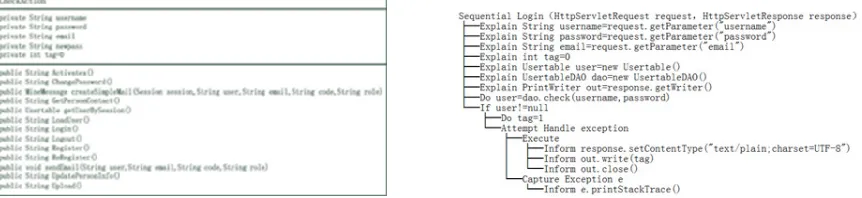
Figure 5. Model of concept class diagram. Figure 6. The model for the design of the outline.
[image:3.612.293.477.74.268.2] [image:3.612.95.512.561.698.2]Development of PSM Model
The concept of class diagram model and the design blueprint from the platform specific, so in order to make the platform independent model is more close to the operation of the system in the reality, we use the model conversion tool to convert and refine the PIM model. The modules of the following order, for example, show the model of the class diagram of the logical structure and the model of the detailed design of the method, respectively, in Figure 7 and Figure 8.
class serv let
CheckAction - email : String
- newpass: Stri ng - password: String - tag: int = 0 - username: String + Acti vatex(): Stri ng + ChangePassword(): String
+ createSimpl eMai l(session:Stri ng, user:String, emai l:String, code:String, rol e:Stri ng): Mi meMessage + GetPersonContact(): String
+ getUserBySessi on(): Usertable + LoadUser(): Stri ng + Login(): String + Logout(): Stri ng + Regi ster(): Stri ng + ReRegister(): String
+ sendEmai l(user:Stri ng, email:Stri ng, code:String, role:String): voi d + UpdatePersonInfo(): String
+ Upload(): Stri ng
[image:4.612.88.528.159.272.2]
Figure 7. A class diagram of a logical structure. Figure 8. A model for the detailed design of the method.
Through model transformation, a class diagram of logical structure and a model for detailed design of the method can be obtained. A class diagram that implements the structure, as shown in Figure 9, and a model for the implementation of the method, are shown in figure 10. The structure of class diagram and the method of construction, the model is closer to the real implementation of the platform.
Figure 9. A class diagram of the implementation structure. Figure 10. A model for the construction of a method.
Concluding Remarks
In the software visual automation service system, there are 10 packages and 79 classes for the module of order management. In the construction phase of the project, we only need to add a small amount of coding on the implementation details, such as the control of the format. This saves about 80% of coding effort and improves productivity by 18.6%. In addition, in the testing phase, when the test case with the same strength is run, the logic error found is reduced by nearly half, and the time of debugging logic error is shortened significantly. Finally, productivity increased by 28.6%.
[image:4.612.95.526.364.463.2]Acknowledgements
This research is sponsored by the Project of National Science and Technology Supporting Program for the Twelfth Five-years Plans(2014BAH25F03),and the software Engineering Discipline Construction Project of Beijing Information Science and Technology University (5121723402).
Reference
[1] Zhang Qingbo. Research and design of code generation based on MDA model. [J]. modern computer, 2015 (9): 73-79. (in Chinese).:
[2] Xiao Xiangbo, Liu Jianbin, Li Jia. Application of model driven technology in performance appraisal system [J]. enterprise technology development, 2016 (6): 17-18.(in Chinese).
[3] One day, Zhang Yan in the science, etc.. Based on the MDA design pattern modeling and model transformation [J]. Journal of software, 2008, 19 (09): 2203-2217. (in Chinese).
[4] Su Hongjun, Yan Yunshan, Zhen Zhenhua. Model driven conversion from UML model to N layer Web model [J]. computer applications, 2014, 34 (04): 1161-1164.(in Chinese).
[5] Zhou Hai, Zhang Ye. Analysis on the modeling technology of the research and application in software development [J]. decision and information: Kan, 2016 (7): 306-307(in Chinese).
[6] Harmon P. The OMG’s model driven architecture and BPM [J]. Business Process Trends, 2004, 2 (5) : 1-11.
[7] Li Zonghua, Zhou Xiaofeng, Gu Aihua, et al. A review of the modeling methods of CIM and the formal representation of models. [J]. computer applications research, 2014, 31 (10): 2896-2901. (in Chinese).
[8] Guan Lixia. Research and implementation of software development method based on MDA [D].Nanjing: Southeast University, 2005.(in Chinese).
[9] Du Yi, Guo Danhuai, Chen Xin, et al. A method based on model driven to generate system visually [J]. Journal of software, 2016, 27 (5): 1199-1211. (in Chinese).
[10] Lv Ruifeng, Wang Gang, ask Xiao Xian, et al. Process modeling for computing independent layer based on model driven framework [J]. computer integrated manufacturing system, 2008, 14 (5): 868-874.(in Chinese)..
[11] Liu Jianbin. Methods of exporting models and views represented by a program in process blueprint [J]. Computer Engineering, 2009, 35 (21): 13-16. (in Chinese).
[12] Liu Jianbin. Methodology for the design of process blueprints [M]. Beijing: Science Press, 2005. (in Chinese).
[13] OMG. Committed Companies and Their Products [EB/OL]. (2016-9-12). http://www.omg.org/ mda/ committed-products.htm.