2017 2nd International Conference on Computer, Network Security and Communication Engineering (CNSCE 2017) ISBN: 978-1-60595-439-4
Simulation of Three-dimensional Free-form Surface Normal Machining
by 4SPS+SPR Parallel Machine Tool
Yong YE
*Department of Mechanical Engineering, Chongqing College of Electronic Engineering, Chongqing 401331, P R China
*Corresponding author
Keywords: Parallel machine tool, 3D free-form surface, Normal machining.
Abstract. In order to facilitate and efficiently analyze by simulation during normal machining 3D free-form surface with 4SPS+SPR parallel machine tool, by using powerful modeling function of SolidWorks software to carry out modeling for three-dimensional entity of parallel machine tools. First, the simulation mechanisms of parallel manipulators are created by CAD variable geometric method. Second, a 3D free-form surface and a guiding plane of tool path are constructed above the moving platform of the simulation mechanism, and the tool axis of simulation parallel machine tools are retained perpendicular to the 3D free-form surface, then the simulation parallel machine tool for machining a 3D free surface is created. Third, in the light of the prescribed tool path which is combined with the parallel machine tool, the driving limbs and pose of the moving platform of parallel machine tool are solved automatically and visualized dynamically. The simulation results show that the approach can be used machine any unknown surface without compiling computer program, and is also advantageous from viewpoint of accuracy and repeatability.
Introduction
A 4SPS+SPR Parallel Robot and Its Simulation Mechanism
[image:2.612.240.371.112.289.2]Solving the Freedom
Figure 1. The 2upu+spr parallel robot.
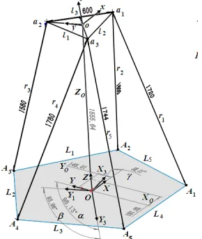
A 4SPS+SPR parallel robot includes a (moving) platform m, a (fixed) base B, four SPS-type driving limbs with linear actuators, and a SPR-type driving limbs with a linear actuator, as shown in Fig. I. Where, m is an equilateral triangle △a1a2a3 with three sides li=l (i=1,2,3) and a center point o; B is an equilateral pentagon A1A2A3A4A5 with five sides Li=L, five joints Ai and a center point O.
Each of the four SPS-type driving limbs ri(i=1,2,4,5) connects m to B by a spherical joint S at ai, a
prismatic joint P, and a spherical joint S at Ai. One SPR-type driving limb r3 connects m to B by a
revolute joint R at a3, a prismatic joint P, and a spherical joint S at A3.
The axis e of R at a3 is parallel with l2 and perpendicular to r3. ri (i=1,…,5) are the driving limbs.
Let {m} be a coordinate frame o-xyz fixed on m at o, {B} be a coordinate frame O-XYZ fixed on B
at O. The DOF of mechanism is calculated from a revised Kutzbach Grubler equation as below:
∑
=− + − − =
g
i
i M
M g
g M
1
0 0 1)
( 6
5 4 ) 3 9 1 5 1 ( ) 1 15 12 (
6× − − + + × + × − =
=
Constructing the Simulation Mechanism
[image:2.612.234.379.560.732.2](1) Construct an equilateral pentagon(A1A2A3A4A5) B and an equilateral triangle △a1a2a3 by the polygon command, set L=1000mm, l=800mm; Construct five lines ri(i=1,2,3,4,5), and connect the
two ends of lines r1 and r2 to m at a1 and to B at A1 and A2, connect the two ends of lines r4 and r5 to
m at a3 and to B at A4 and A5, connect the two ends of line r3 to m at a2 and to B at A3, thus, the four SPS-type driving limbs are constructed;Construct an auxiliary line e at a2, set e∥a1a3 and e⊥r3, thus, the SPR-type driving limb is constructed.
(2) Suppose that moving platform m is rotated about (Z, Y1, X2) by three Euler angles (α, β, γ), namely, a rotation of α about Z-axis, followed by a rotation of β about Y1-axis, and a rotation of γ
about X2-axis. Here, Y1 is formed from Y rotating about Z by α, and X2 is formed from X1 rotating about Y1 by β. ∥denotes a parallel constraint, ⊥ denotes a perpendicular constraint. According to the rotation relationship between {m} and {B}, the geometric constraints Y1⊥Z, Y1⊥y, and X2∥x
must be satisfied.
(3) Construct a line Zo, connect its two ends to m at o and to B at point c, and set Zo⊥B; Give
each of distances from c to Y, X, and o the initial driven dimensions (Xo=187.52mm, Yo=145.01mm, Zo=1555.64mm) in length.
(4) Give each of the angles between Y and Y1, X1 and X2, Y1 and Y2 a driven dimension
α=98.13°, β=93.88°, γ=12.11o.
When varying the driving dimension of ri, the driven dimensions Xo, Yo, Zo, α,β, γ are solved
automatically and visualized dynamically. Similarly, the five driving dimensions can be solved from the driven dimensions.
The 4SPS+SPR Parallel Machine Tool and Its Simulation Mechanism
The 3D Free-form Surface s and Guiding Plane PO of Tool Path
Before creating simulation PMT, the guiding plane Po, 3D free-form surface s and tool path w for maching s must be created by the 3D modelling technique. Generally, there are two kinds of tool path w for machining s. One is a linear reciprocation tool path; the other is a rectangle or circle spiral tool path,see Fig. 3 A guiding plane P0 of the tool path and a 3D free-form surface s are created as follows.
(a) linear reciprocation tool path (b) rectangle tool path (c) circle spiral tool path
Figure 3. Three kinds of tool paths.
(1) Modify B of the simulation mechanism, construct several datum planes Pj (j=1,2,…k), and set
them parallel to each other and perpendicular to B by the reference plane command.
(2) Based on the prescribed curve data or curve equation, construct a spline uj on the jth plane Pj
(j=1,2,…k) by the sketching spline command or data table, and arrange each spline curve with respect to Po above m of the simulation mechanism.
(3) Construct a smooth and continuous 3D free-form surface s from all uj (j=1,2,…k) by loft modelling technique and attached on B above m and under Po.
(4) Modify B of the simulation mechanism, and construct a datum plane P0 by the reference plane
command. Set Po∥B, and give the distance from Po to B a fixed dimension h. Construct a linear
reciprocation w on Po, and transform it into a guiding plane of the tool path by the plane-forming
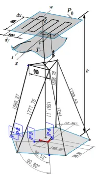
Figure 4. Configuration of the simulation 4sps+spr pmt along a linear reciprocation tool path.
The Simulation Mechanism of 4SPS+SPR Parallel Machine Tool
The simulation PMT with a linear reciprocation tool path is created for normal machining of s, see Fig. IV. The creation procedures are explained as follows:
(1) Transform all driving dimensions of extension ri into the driven dimensions by using the dimension command, the value of it are varied from the pose of PMT.
(2) Construct a line T of tool at point o, coincide the tip of T with s at point p by using coincident constraint command, set T⊥m, T⊥s, set T=500mm.
(3) Construct a guiding line g, connect its two ends to s at point p and to Po at point d,
respectively, by the coincident constraint command, and set g⊥Po.
(4) Give each of the distances from point d to the left side and the lower side of Po the driving
dimensions dxand dy, respectively. When varying the driving dimensions of dx and dy along the w,
the driven dimensions of active legs ri andα,β,γ are varied automatically.
When a linear reciprocation w on Po is used to machine s, its construction procedures are
described as follows:
(1) Determine the machining range (dymin, dxmin, dymax, dxmax) and the feed speed (δx, δy) each time.
Set dymin = dxmin = 200, dymax = dxmax =1500, δx = δy = 50mm each time.
(2) Retain dy=dymin, and gradually increase dx by δx each time from dxmin to dxmax by using the
dimension automatic fill command.
(3) Retain dx=dxmax, and gradually increase dy by δy each time from dymin to dymax by using the
dimension automatic fill command.
(4) Retain dy=dymax, and gradually increase dx by−δx each time from dxmax to dxmin by using the
dimension automatic fill command.
(5) Repeat the steps 2–4 above, till dy=dymax and dx=dxmax.
The Simulation Results
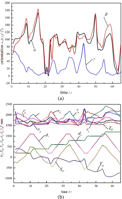
When varying the driving dimensions of dx and dy, the tool T is moved and retained perpendicular
to s at any point. At the same time, the driven dimensions of the active legs in length and rotational angle of motor and the pose parameters (Xo, Yo, Zo, α,β, γ) of the simulation 4SPS+SPR PMT are
(a)
[image:5.612.201.411.66.408.2](b)
Figure 5. The simulation results of the simulation 4sps+spr pmt along a linear reciprocation tool path: (a) change law of α,β,γ , (Β) change law of ri and pose parameters.
Conclusions
Using advanced CAD software, any prescribed 3D free-form surface can be constructed from several precision splines. Based on the 3D free-form surface, the driven dimensions of the driving limbs and the pose of the moving platform of the PMT can be solved automatically. The simulation solved results of active legs and pose of platform of the PMT can be transformed into NC codes easily. This approach is straightforward and simple.
A complicated process of machining a 3D freeform surface can be divided into several simple processes to produce its corresponding simulation data. These simulation data in each simple process are used as orderly input into the driving limbs, so that the complicated machining process can be simulated easily.
Acknowledgment
The authors would like to acknowledge the financial support of the Science and Technology Research Project of Chong Qing Education Committee (KJ1503007).
References
[2] Kim B H, Choi B K. Guide surface based tool path generation in 3-axis mill: an extension of the guide plane method[J]. Compute Aided Design, 2000, 32(3):191-199.
[3] Elber G, Cohen E. Tool path generation for freeform surface models[J]. Compute Aided Design, 1994, 26(6): 490-496.
[4] Bechert B A. Venturing into virtual product development[J]. Compute Aided Design, 1996, 28(5): 223-229.
[5] Chen Y D, Ni J, Wu S M. Real-time CNC tool path generation for machining IGES surface[J]. ASME Journal of Engineering for Industry, 1993, 115(4): 480-486.
[6] Hartley P J, Judd C J. Parameterization and shape of B-spline curve for CAD[J]. Compute Aided Design, 1980, 12(5): 235-238.
[7] Gosselin C M, Pereault L, Vailancourt C H. Simulation and computer-aided kinematics design of three-degreed-of freedom spherical parallel manipulators[J]. Journal of Robot System, 1995, 12(12): 857-869.
[8] Lu Y, Xu J Y. Computer simulation machining a 3D free surface by using a 3-RRPU parallel machine tool[J]. The International Journal of Advanced Manufacturing Technology, 2007, 33(9): 782-792.
[9] Lu Y. Computer-aided geometric machining a 3D free surface using a 3-UPU spatial parallel machine tool[J]. The International Journal of Advanced Manufacturing Technology, 2005, 26(10): 1018-1025.
[10]Lu Y. Simulation of machining 3D free-form surface in normal direction using 6-SSP and 4SPS+UPU parallel machine tools[J]. The International Journal of Advanced Manufacturing Technology, 2007, 33(10): 1180-1118.