Simulation of Speed Control of Brushless DC
Motor for four Quadrant Operation
S Ragu1 1
PG scholar, EEE Department, Pondicherry Engineering College, Puducherry-60514
Abstract—Brushless DC (BLDC) motor drives are becoming more popular in industrial, traction applications. This makes the control of BLDC motor in all the four quadrants very vital. This paper deals with the conventional control of three phase BLDC motor. The BLDC motor is controlled in all four quadrant operation without any loss of power; in fact energy is conserved during regenerative period. The conventional controller is very advantageous over other controllers, as it combines the calculation capability of Digital Signal Processor and controlling capability of microcontroller, to achieve precise control. Keywords–Three phase BLDC motor, four quadrant operation, regenerative braking, PI controller.
I. INTRODUCTION
Brushless Direct Current (BLDC) motor is one of the motor types rapidly gaining popularity. The stator of a BLDC motor consists of stacked steel laminations with windings placed in the slots that are axially cut along the inner periphery or around stator salient poles. The rotor is made of permanent magnets and can vary from two to eight pole pairs with alternate north (N) and south (S) poles. In order to rotate a BLDC motor, the stator windings should be energized in a sequence. In the brushless DC motor, polarity reversal is performed by power transistors switching in synchronization with the rotor position. Therefore, BLDC motors often incorporate either internal or external position sensors to sense the actual rotor position or its position can also be detected without sensors. BLDC motors are used in Automotive, Aerospace, Consumer, Medical, Industrial, Automation Equipment and Instrumentation. Several simulation models [1-3] were proposed based on non-linear state-space equations and other methods. BLDC Motor considered in these models is star connected with neutral grounding, but several applications require isolated neutral. Keeping in view merits of these developments, in this work the motor is modeled as star connected with isolated neutral and the voltages supplied are line to line. This paper is organized as follows: Section II describes the three phase BLDC motor, its features, and also the PI control technique, with its special features. In section III, the realization of four quadrant control operation of the BLDC motor is presented. In section IV simulation result in four quadrant drive is given. Section V concludes the proposed work.
II. BRUSHLESS DC MOTOR AND PI CONTROLLER
Brushless DC Motors are driven by DC voltage but current commutation is controlled by solid state switches. The commutation instants are determined by the rotor position. The rotor shaft position is sensed by a Hall Effect sensor, which provides signals as represented in Table I. Whenever the rotor magnetic poles pass near the Hall sensors, they give a high or low signal, indicating either N or S pole is passing near the sensors. Based on the combination of these three Hall sensor signals, the exact sequence of commutation can be determined. These signals are decoded by combinational logic to provide the firing signals for 120°conduction on each of the three phases. The rotor position decoder has six outputs which control the upper and lower phase leg MOSFETs of Fig.1.
. TABLE 1 Clockwise hall sensor signals, phase voltages and drive signals
A. PI Controller
Several papers have been published using digital, and hybrid control [4-5] techniques. The regulation of speed is accomplished with PI Controller. By increasing the proportional gain of the speed controller, the controller’s sensitivity is increased to have faster reaction for small speed regulation errors. This allows a better initial tracking of the speed reference by a faster reaction of the current reference issued by the speed controller. This increased sensitivity also reduces the speed overshooting. The armature current reduces faster, once the desired speed is achieved.
©IJRASET 2014: All Rights are Reserved
168
are tuned conventionally by trial and error method Although this control methodology result in simple, easily-implemented controller that copes well with system uncertainties, system response might not be satisfactory all over the entire operating range.
B. Closed-Loop Controller
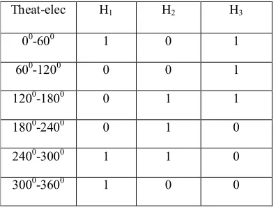
[image:3.612.208.406.288.438.2]The BLDC motor is fed by a three phase MOSFET based inverter. The PWM gating signals for firing the power semiconductor devices in the inverter is injected from a hysteresis current controller [6] which is required to maintain the current constant within the 60 degree interval. Table 2 shows the hall sensor signal for 60 degree interval. It regulates the actual current within the hysteresis band around the reference currents. The reference currents are generated by a reference current generator depending upon the steady state operating mode. The reference currents are of quasi –square wave. They are developed in phase with the back-emf in motoring mode and out of phase in braking mode. The magnitude of the reference current is calculated from the reference torque. The reference torque is obtained by limiting the output of the PI controller. The PI controller processes on the speed error signal (i.e. the difference between the reference speed and actual speed) and outputs to the limiter to produce the reference torque. The actual speed is sensed back to the speed controller and processed on to minimize the error in tracking the reference speed. Thus, it is a closed loop control drive system. Table 2 shows the indication of the hall sensor angle for every 600 .
TABLE 2
. A Function of rotor hall sensors modeled as angle
Theat-elec H1 H2 H3
00-600 1 0 1
600-1200 0 0 1
1200-1800 0 1 1
1800-2400 0 1 0
2400-3000 1 1 0
3000-3600 1 0 0
C. Modeling of Hysteresis Controller
Hysteresis controller limits the phase currents within the hysteresis band by switching ON/OFF the power devices for high speed [7] bldc motor. The switching pattern is given as:
If I a err
> UL, S1 is on and S4 is off
If I aerr < LL, S1 is off and S4 is on
If I berr > UL, S3 is on and S6 is off
If I b err
< LL, S3 is off and S6 is on
If I cerr > UL, S5 is on and S2 is off
If I cerr < LL, S5 is off and S2 is on
Where Ik
err = Ik
err - Ik
meas
and UL, LL are the upper and lower limits of hysteresis band. Thus, by regulating the current desired quasi-square waveforms can be obtained.
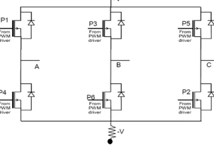
Fig.1 Three phase Inverter Circuit to BLDC Motor
Fig.1 shows the three phase inverter circuit to BLDC Motor. The PWM module used here simplifies the task of generating multiple synchronized Pulse Width Modulated (PWM) outputs. It has six PWM I/O pins with three duty cycle generators. The three PWM duty cycle registers are double buffered to allow glitch less updates of the PWM outputs. For each duty cycle, there is a duty cycle register that will be accessible by the user while the second duty cycle register holds the actual compared value used in the present PWM period.
D. Modeling of Reference Current Generator
[image:4.612.184.434.387.537.2]The desired reference currents are injected into the hysteresis controller. The magnitude of the reference current is determined from the reference torque and back-emf constant. The incoming or outgoing direction of the current is determined from hall sensors output and the operating mode. The reference currents for four steady state operations are modeled as shown in Table III (Forward motoring and reverse braking) and Table IV (Reverse motoring and forward braking:
TABLE 3.Reference current for forward motoring and reverse braking
H1 H2 H3 Ia
ref Ib
ref Ic
ref
1 0 1 0 I* -I*
0 0 1 I* 0 -I*
0 1 1 I* -I* 0
0 1 0 0 -I I
1 1 0 -I 0 I
1 0 0 -I I 0
TABLE 4.
Reference current for forward braking and reverse motoring.
H1 H2 H3 Iaref Ibref Icref
1 0 1 0 -I* I*
0 0 1 -I* 0 I*
0 1 1 -I* I* 0
0 1 0 0 I -I
1 1 0 I 0 -I
Conventional PI controller is used as a speed controller for recovering the actual motor speed to the reference. The reference
and the measured speed are the input signals to the PI controller. The KP and KI values of the controller are determined by trial
and error. The controller output is limited to give the reference torque.
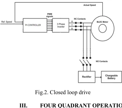
[image:5.612.202.402.143.319.2]Figure 2 gives the closed loop control drive of the brushless dc motor with rectifier and chargeable battery.
Fig.2. Closed loop drive
III. FOUR QUADRANT OPERATION
There are four possible modes of quadrants of operation [8-11] using a Brushless DC Motor. In an X-Y plot of speed versus torque in Fig.3, Quadrant I is forward speed and forward torque. The torque is propelling the motor in the forward direction. Conversely, Quadrant III is reverse speed and reverse torque. Now the motor is “motoring” in the reverse direction, spinning backwards with the reverse torque. Quadrant II is where the motor is spinning in the forward direction, but torque is being applied in reverse. Torque is being used to “brake” the motor, and the motor is now generating power as a result. Finally, Quadrant IV is exactly the opposite. The motor is spinning in the reverse direction, but the torque is being applied in the forward direction. Again, torque is being applied to attempt to slow down the motor and change its direction to forward again. Once again, power is being generated by the motor.
[image:5.612.199.420.508.693.2]The BLDC motor is initially made to rotate in clockwise direction, but when the speed reversal command is obtained, the control goes into the CW regeneration mode which brings the rotor to the standstill position. Instead of waiting for the absolute standstill position, continuous energization of the main phase is attempted. This rapidly slows down the rotor to a standstill position. Therefore, there is the necessity for determining the instant when the rotor of the machine is ideally positioned for reversal. Hall-effect sensors are used to ascertain the rotor position and from the Hall sensor outputs, it is determined whether the machine has reversed its direction. This is the ideal moment for energizing the stator phase so that the machine can start motoring in the CCW direction.
Fig.4 Operating Modes
When BLDC motor (Fig.4) is operating in the first and third quadrant, the supplied voltage is greater than the back emf which is forward motoring and reverse motoring modes respectively, but the direction of current flow differs. When the motor operates in the second and fourth quadrant the value of the back emf generated by the motor should be greater than the supplied voltage which are the forward braking and reverse braking modes of operation respectively, here again the direction of current flow is reversed.
The flowchart for the four quadrant controller is presented in Fig.4.
IV. RESULTS & DISCUSSION
BLDC motor and Battery specifications:
Rated voltage : 24
Rated current : 2.4A
Rated Speed : 3000rpm
Rated Power : 60w
Number of Poles : 8
Number of Phases : 3
Battery voltage : 6V
Charging current : 1.3Ahr
Simulation results for four quadrant drive of BLDC motor at various load and speed was conducted and some of the graphs for speed, torque, current and back emf (Fig.6-10) waveforms have been shown in the following section.
A. Speed controller at different load conditions
Fig.6 Speed at 20% load & 3000rpm
Fig.7 Speed at 50% load and 1500 rpm
Fig.9Back EMF (voltage) at 20% load & 3000rpm
Fig.10 Electro magnetic torque at 20%load & 3000rpm
B. Speed reversal at different load conditions
Following Fig.11-13 shows the speed reversal, back emf and charging battery voltage of the bldc motor at 50% loading when speed changes from 400 to -400 rpm.
Fig.11 Speed change from 400rpm to -400rpm at 50% load
Fig.12Three phase back emf waveform at 50% load condition & 400rpm to -400rpm
Fig.14Energisation of battery with load of 75% when compared with 400rpm to -400rpm
Fig.15Energization of battery with no load when compared with 400rpm to -400rpm
In the Fig 14 and 15 voltage waveforms are shown which indicate the charging of battery due to switch over for reversing speed of the motor. In the test conducted for higher speed reversal with light load gives more charging voltage for short duration. But for lower speed reversal with more loads gives less voltage for little longer duration. In both the cases battery gets the advantage of either high voltage for short duration or low voltage for longer duration
V. CONCLUSION
In conventional control of BLDC motor, PI speed controller and hysteresis current controller is used. A control scheme is proposed for BLDC motor to change the direction from CW to CCW and the speed control is achieved both for servo response and regulator response. The motor reverses its direction almost instantaneously, it will pass through zero, but the transition is too quick. The time taken to achieve this braking is comparatively less. The generated voltage during the regenerative mode can be returned to the supply mains which will result in considerable saving of power. This concept may well be utilized in the rotation of spindles, embroidery machines and electric vehicles where there is frequent reversal of direction of rotation of the motor.
REFERENCES
[1] P.Pillay and R.Krishnan, “Modeling, simulation and analysis of permanent-magnet motor drives, part-II: the brushless DC motor drives,” IEEE Trans. on Industry Applications, vol. 25, pp.274-279, March/April 1989.
[2]. S.K.Safi, P.P.Acarnley and A. G. Jack. “Analysis and simulation of the high-speed torque performance of brushless DC motor drives,”Proc. Of IEE, vol 142, no.3, p.p.191-200, May 1995.
[3] Byoung-Kuk Lee and Mehrdad Ehsani, “Advanced Simulation Model for Brushless DC Motor Drives”, Electric Power Component And Systems, vol.31 pp.841-868, 2003.
[4] Leonard N. Elevich, "3-Phase BLDC Motor Control with Hall Sensors Using 56800/E Digital Signal Controllers", AN1916, Application Note, Rev. 2.0, 11/2005.
[5] A fjei, O. Hashemipour, M. A. Saati and M. M. Nezamabadi, “A New Hybrid Brushless DC Motor/Generator Without Permanent Magnet”, IJE Transactions B: Applications Vol. 20, No. 1, , pp.77-86. April 2007
[6] Performance Improvement of BLDC Motor with Hysteresis Current Controller A.Purna Chandra Rao1, Y.P.obulesh 2, CH. Sai babu Vol. 2, Issue 12, December 2013.
[7] J.D.Ede, ,Z.Q.Zhu and D.Howe,” Control of high speed permanent magnet brushless DC motors”, in Proc.5th Int,Conf..Electrical Machines and Sytems’,vol.2, ,pp 909-912 Aug 2001
[8] Vinatha U,Swetha Pola, Dr.K.P.Vittal, “Simulation of four quadrant operation and speed control of BLDC motor on MATLAB” IEEE Region 10 conference Proceedings pp. 1-6 TENCON 2008.
[9] R. Krishnan, Sung-Yeul Park, and Keunsoo Ha, “Theory and Operation of a Four-Quadrant Switched Reluctance Motor Drive With a Single Controllable Switch—The Lowest Cost Four-Quadrant Brushless Motor Drive”, IEEE Transactions on Industry Applications, Vol.41, No. 4, ,pp.1047 -1055 2005
[10] V.U,S.Pola, and K. P.Vittal, “Simulation of four quadrant operation& speed control of BLDC motor on MATLAB/SIMULINK,” in Proc. IEEE Region 10 Conference, , pp. 1–6. 2008