6
I
January 2018
Harmonic Reduction using Passive Filter (reducing
electrical pollution)
S. Aruna M. E1, P. Priyanka2, A. Sri Kaviya3, G. Sathyan4 1, 2, 3, 4
Electrical and Electronics Engineering, Kongu Engineering College, Perundurai.
Abstract: Now a-days the usage of modern drives are extended, the imbuement of harmonics has been produced rapidly. To reduce the harmonics imbued in the transmission line the filters are used as a piece of the system. The filters are used to diminish the distortion caused by the source and drives. A couple of sorts of filters are accessible; however the passive filter is one of the convincing among them. The passive filter is more feasible in restricting the voltage distortion caused by the nonlinear loads used in the endeavors. Unmistakable decisions for the filter arrangement should be considered for settling on an official decision for filter plans. The layout and execution of the passive filter will be steady of diminishing the current and voltage harmonics. Most of the power quality issues are caused because of the nonlinear loads, induction heater and power equipment devices. These sorts of weights will make the harmonics which will destroy the sinusoidal nature of the AC supply. The most natural approach to diminish harmonics is by introducing passive filter in our system. In this paper we discussed the power philosophies of passive filter which alleviate harmonics and keep up waveform sinusoidal.
Keywords: Harmonics, Passive filter, Transmission line.
I. INTRODUCTION
There is a great emphasis about power quality and particularly the issue of harmonics distortion because of the joining of more non-linear loads in a typical present day plant. Further, power electronic based devices are for the most part being used for inverter, rectification and distinctive applications. Not withstanding the fact that these devices are more suitable they create and imbue harmonics into the power system. For the most part, adequacy examinations in power systems think about without distortion waveforms, that is the voltage and current waveforms are believed to be sinusoidal. A harmonics is a sinusoidal part of an intermittent wave having a frequency that is a vital different of the fundamental frequency. The standard of harmonics in power systems has been the static power converter used as rectifiers, variable speed drives, switched mode supplies, frequency changers for induction heating. Since nonlinear loads speak to a reliably extending level of the total store of a mechanical or modern power system, harmonics examinations have transformed into a basic bit of general system diagram and operation. Fortunately, the accessible programming for harmonics examination has furthermore created.
Guidelines for the acknowledgment of harmonics distortion are particularly characterized in IEEE Standard 519-1992. By showing power system impedances as a component of frequency, an examination can be had to choose the effect of the harmonics. Non-linear loads on the system are the major responsibility for voltages and current harmonics in the power system. The harmonics level gets extended by the utilization of power electronic gadgets.
This prompts the purpose behind minimization in relentless reliability and stability. To beat these issues, it is a need to keep up power quality. These issues rise in view of the electrical unsettling influence. Most of the aggravation depends upon the amplitude or frequency. Harmonics causes overheating of motors, cables, transformers. Moreover reduce the future of various components. With the snappy upgrades and usage of nonlinear loads, the powerling technique is basic over the harmonics. So the passive filter is used to mitigate harmonics.
II. HARMONICS AND ITS TYPES
The integral multiple of the sinusoidal voltage or current having the frequencies at which the supply system is designed (named the key frequency; for the most part 50 or 60 Hz). The distorted waveform can be wrecked into the essential frequency and the harmonics. The distortion occurs generally due to the non-linear characteristics of the drives and loads in a system. Harmonics portion of current order n can be represented as
A. Odd order B. Even order
Odd harmonics may be expressed as:
= sin2
Where n = 3, 5, 7...etc and In is the amplitude of harmonic portion of order n. In fact, even harmonics may be expressed as:
= sin2
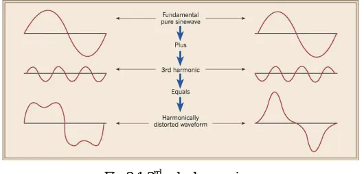
[image:3.612.177.442.205.332.2]Where n = 2, 4, 6...etc and In is the amplitude of harmonic fragment of order n. The fig 2.1 shows the the distroted wave form of the 3rd order harmonic in a system
Fig 2.1 3rdorder harmonics C. Impacts of Harmonics
Harmonics are not appealing in numerous applications and operations of electrical power system; thusly it has wide antagonistic impacts on the system. The impacts of harmonics may be classified as:
1) Reverberation and Impact on Capacitor Banks 2) Poor Damping
3) Impacts of Harmonics on rotating Machines 4) Impacts on Transformer
5) Impacts on Transmission Lines
6) Harmonics Interference with Power System Protection 7) Impacts of Harmonics on Consumer equipments
D. Zones of Harmonics
The methodologies used to decrease harmonics distortion issue differs from place to place. To control the harmonics distortion actuated in the distribution feeder and end customer power system, a couple of systems have been used. They are:
1) On Utility Distribution Feeders 2) In End-User Facilities
III. CONTROL METHODS
Filters are used to evacuate the unwanted frequency that actuates due to non-linear characteristics of some electronic devices. Among different approaches to beat the harmonics or keep them inside quite far are by incorporating filter in the system.
There are three sorts of filters. 1) Passive filters
2) Active filters 3) Hybrid filters
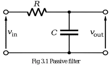
Passive filters are used to reduce a particular harmonics frequency, so number of passive filters increase with increase in number of harmonics on the system. They can be characterized into:
4) Passive shunt filter 5) Passive series filter
Fig 3.1 Passive filter
IV. PROPOSED SYSTEM
[image:4.612.186.420.242.342.2]The proposed system to reduce harmonics using passive filter according to IEEE standards and to grow power quality of the system showed up in fig 4.1
Fig 4.1 Square Layout of Proposed System
A. Hardware Execution
The hardware setup have been shown up in the fig 4.2
Fig 4.2 Hardware setup
B. AC Supply
Three-phase electric power is a normal system for substituting current electric power generation, transmission, and distribution. It is a sort of polyphase system and is the most generally perceived procedure used by electrical lattice worldwide to transfer power.
C. Variable Frequency Drive
Variable frequency drives are known as frequency inverter, AC drives etc. It is an electric gadget to change utility power source to variable frequency to control AC motor operated in variable speed operation.
Two basic concerns:
[image:4.612.182.429.395.580.2]D. AC Motor
An electric motor is an electrical machine that converts electrical energy into mechanical energy. The transform of this is the difference in mechanical energy into electrical energy and is done by an electric generator, which has much in a comparative way as a motor.
V. SIMULATION
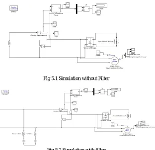
[image:5.612.153.465.217.519.2]The introduction of all harmonics examination still depends upon the estimation of amplitude and phase angle of the harmonic components. In this paper, we have used Fast Fourier Transform (FFT) worked in instrument accessible in MATLAB. In fig 5.1 show the system consists of non-linear load which make part to the induce of harmonic in the system which will cause the some damage to the meachines. In fig 5.2 the passive filter is induced in the system which will helps in reducing the harmonic intration in the system.
Fig 5.1 Simulation without Filter
Fig 5.2 Simulation with filter
VI. RESULTS AND DISCUSSION
A. Simulation Result
[image:5.612.181.431.605.720.2]In the fig 6.1 shows the Total Harmonics Distroction (THD) that occure at the time of using non linear load have been shown with the help of FFT analysis. In fig 6.2 shows the reduction on Total Harmonics Distrotion (THD) by introducing the passive filter in the system.
Fig 6.2 FFT analysis with filter
B. Hardware result
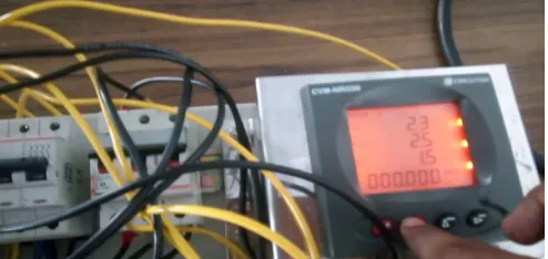
The fig 6.3 shows the output of the system when the passive filter is introduced, where the VFD is used. Due to the introducing of the VFD the harmonic is introduced in the system. To reduce the harmonic passive filter is implemented.
Fig 6.3 Hardware result with passive filter
C. Formulae
Let us assume connected load = X KVA Initial power factor = 0.85 Proposed power factor = 0.98
Reactive power demand at 0.85 PF = Xx sin (arc cos 0.85) =A Reactive power demand at 0.98 PF = Xx sin (arc cos 0.98) =B Required compensation from the filter = A-B = C KVAR
For nominal 440 system, the net Y equivalent filter reactance (Capacitive) Xmax = KV2 x 1000 = 0.4402 x 1000
KVAR C
Xfilter is the difference between capacitive reactance and inductive reactance at fundamental frequency Hence Xmax = Xcap – XL
For tuning at 4.7th Harmonic (h) Xcap = h2 XL = 4.72 XL The desired cap reactance Xcap = Xfilter h2 = D h2-1
At this point it is not known whether the capacitor is rated for 440V. To achieve this KVAR = KV2 x 1000 = 0.4402 x 1000
[image:6.612.185.432.322.439.2]Filter Reactor size XL(FUNDS) = Xcap = D ohm h2 h2
L = XL(FUNDS) x 1000 =EmH 2pi x 50
D. Calculation
Give us a chance to expect associated stack = 5 HP = 3.73KW Beginning power factor = 0.8
Proposed power factor = 0.98
Reactive power request at 0.8 PF = 4.66∗sin( cos0.85) = 2.7 KVAR
Reactive power request at 0.98 PF = 4.66∗sin( cos0.9.8) = 0.932 KVAR Required remuneration from the filter = 2.0 KVAR
For ostensible 415 system, the net Y equalent filter reactance (Capacitive) Xmax = KV2 x 1000 = 0.4152 x 1000
KVAR 2.0 = 86.11ω
The coveted capacitive reactance at Xcap = Xfilter h2 = 86.11* 3.78232 h2-1 3.78232-1
= 92.57 ω
KVAR at 415V
KVAR = KV2 x 1000 = 0.4102 x 1000 KVAR 92.57 = 2.0 KVAR Filter Reactor estimate
XL(FUNDS) = Xcap h2 = 92.57 ohm
3.7282
= 6.47 Ω
L = XL(FUNDS) x 1000 2pi x 50 = 6.47 x 1000 2 x π x 50
=20.60mH
E. Tabulations
Fig 7.1 shows the maximum individual frequency voltage harmonics SCR at PCC Indidual Frequency Voltage Harmonics (%)
10 2.5% - 3.0%
20 2.0%-2.5%
50 1.0-1.5%
100 0.5%-1.0%
1000 0.05%-0.10%
*
SCR: Short circuit ratio *
[image:8.612.185.427.135.218.2]PCC: Point of common coupling
Fig 7.2 shows the maximum harmonic current distortion in percent of IL for general distribution systems
Fig 7.2 Lmitations of current harmonics
Even harmonics are limited to 25% of the odd harmonic limits above.
VII.CONCLUSION
The passive harmonics filters are a suitable, linearforward and saving other option to counter the issue of harmonics rising in pretty much nothing and tremendous scale power systems or system including non-direct loads. Versatility in power can't be accomplished using passive filters however in spite of what may be normal power systems are dynamic in nature and thusly there is a prerequisite for versatile and computerized control. However, passive filters are always seen as a possible choice from conservative perspective. Harmonics makes mischief to the electrical systems and now and again be hazardous. Passive filter are effective in constraining voltage and current distortion caused by nonlinear loads. Passive filter gives low impedance route to the harmonics current.
REFERENCES
[1] The harmonic mitigation in Induction Furnace using hybrid filter by M. A. Tahasildar*, Prachi Chougule#1, Anuja Kadam#2, Ashwini Patil#3, Tejswini Sisal #4,Laxmi Teli #5 Asst. Professor, Dept. of Electrical Engineering, Sanjay Ghodawat Institutes, Kolhapur, India 1-5,UG Students, Dept. of Electrical Engineering, Sanjay Ghodawat Instiutes, Kolhapur, India [email protected]
[2] H. Rudnick, J. Dixon and L. Moran, “Active power filters as a solution to power quality problems in distribution networks,” IEEE Power and Energy
Magazine, Sep/Oct 2003, pp. 32-40
[3] Instantaneous power theory and applications to power conditioning (Hirofumi Akagi, Edson Hirokazu Watanabe)
[4] “Design of passive filters for reducing harmonic distortion and power factor in two pulse rectifier systems using optimization" by D.Maheswaran,N.Rajasekar
and L.Ashok Kumar ,department of Electrical,Tamilnadu newsprint and papers Limited,kagithapuram,Karur,Tamilnadu.
[5] Ying-Tung Haiao, “Design of filters for reducing harmonic distortion and correcting power factor in industrial distribution systems”, Tamkang jour of
sci and engg. Vol.4,No.3,pp 193-199 (2001).
[6] J.S. Subjak and J. S. McQuilkin, “Harmonics - Causes, effects, measurements, and analysis: An update,” IEEE Trans. Ind. Appl.IA-26:1034-1042, 1990.
[7] R. P. Stratford, “Rectifier harmonics in power systems,”IEEE Trans. Ind. Appl.Vol. IA-16:271-276, 1980.
[8] Andrez pietkiewicz, ‘Proper selection of passive and active power quality filters for the mitigation of main harmonics’ White paper ,dec 2003.
[9] K. Umezu, “AC power supply system measures harmonics from electronic equipment,” Nikkei Electron. Asia (May): 52-55, 1993.
[10] Duffey, C. K. and Stratfort, R. P., “Update of harmonic standard IEEE-519: IEEE recommended practices and requirements for harmonic control in electric
power systems,” IEEE Trans. on Industry Applications, Vol. 25,pp. 1025-1034 (1989).
[11] Su Chen ,GCza Jobs, ‘Analysis and Comparison of Passive & Active Harmonic Suppression Filters in Distribution Systems’,2000 IEEE ,pp 615-619.
[12] Yaow -Ming Chen , ‘Passive filter design using genetic algorithms’, IEEE trans .Industrial Electronics , vol 50 ,pp 202-207 ,feb .2003
[13] Vishal Verma, ‘Genetic-Algorithm-Based Design of Passive Filters for Offshore Applications’ , IEEE TRANSACTIONS ON INDUSTRY
APPLICATIONS,VOL. 46, NO.4, JULY/AUGUST 2010
[14] R. Prasad, P. D. Ziogas and S. Manias, "A novel Passive wave-shaping method for single phase Diode Rectifiers", IEEE Trans. on Industrial Electronics,
Vol.37, No.6,Dec.1990, pp. 521-530.
[15] Ji Yanchao, Liang Xiaobing, Liu Zhuo, Jin Jisheng and Liu Xinhua, "An improved Passive Input Current Waveshaping Method for Single-Phase Rectifier,"
Industrial Electronics,Control and Instrumentation, IEEE IECON, Vol. 2, 1996, pp 695-699.
[16] Hussein A. Kazem, “Input Current Wave shaping Methods Applied to Single Phase Rectifier,” Proceeding of International Conference on Electrical
Machines and Systems, Oct 8-11, Seoul, Korea, 2007.
[17] Peng.F.Z., Akagi.H and Nabase, A.,“Compensation characteristics of the combined system of shunt passive and series active filters,” IEEE Trans. on Industry Applications, Vol. IA-29, pp. 144-151 (1993).
[18] Chou, C. J., Liu, C. W., Lee, J. Y. and Lee, K.D., “Optimal planning of large passive-harmonic-filters set at high voltage level,” IEEE Trans. on Power
Systems, Vol. 15, pp.433-439 (2000).
[image:8.612.36.577.388.716.2]