Technology (IJRASET)
Wireless Human Detection Robot
Rahul Krishna K1, Meera A2, Nikhil Mathew3
1,2,3
EEE Department, Mar Athanesius College of Engineering, Kothamangalam
Abstract: The advent of new high-speed technology and the growing computer capacity provided realistic opportunity for new robot controls and realization of new methods of control theory. This technical improvement together with the need for high performance robots created faster, more accurate and more intelligent robots using new control devices, new drives and advanced control algorithms. This project deals with a live human detection robot. A wireless remote controlled robot which employs a PIR sensor, detects the presence of human being and indicates it to the user. As it is a wireless robot it can be easily mobilized and controlled. This can be used to detect terrorists/thieves hiding inside a building. This can also be used for rescue operations in earthquake.
Keywords: Robot, intelligent robots, Wireless, Remote controlled, PIR Sensor
I. INTRODUCTION
Natural calamities do occur and they are unstoppable. But humans are becoming increasingly aware of the concept of intelligent rescue operations in such calamities so that precious life and material can be saved. Still there are lots of disasters that occur all of a sudden and earthquake is one such thing. Earthquakes produce a devastating effect and they see no difference between human and material. Hence a lot of times humans are buried among the debris and it becomes impossible to detect them. A timely rescue can only save the people who are trapped and wounded. Detection by rescue workers becomes time consuming and due to the vast area that gets affected it becomes more difficult. So the project Wireless Human Detection Robot is an autonomous robotic vehicle that moves in the earthquake prone area and helps in identifying alive people. The main aim of the project is to detect the human being by using a wireless remote controlled robot, which have the sensors that detects the presence of the human being and indicates the presence to user. As it is a wireless robot, it can be easily mobilized and controlled. This can also be used to detect terrorists/thieves hiding inside the building.
A unique Passive Infrared sensor is used in the project which emits infrared rays to detect humans. As live human body emits thermal radiation it is received and manipulated by the PIR sensor to detect humans. Once the people are located it immediately gives audio and visual alerts to the authorities so that help can be given faster. This PIR sensor is placed on a robot that can manoeuvre in the earthquake prone areas. The robot is driven on a geared dc motor. The robot consists of a three wheel geared drive with DC motors attached to perform forward, reverse, left and right movement.
The controlling device of the whole system is a Microcontroller to which RF receiver, PIR sensor and DC motors are interfaced. The remote control has control buttons interfaced to RF transmitter. Whenever a button is pressed, the data related to that button will be transmitted through RF transmitter. This data will be received by RF receiver and is fed to the microcontroller. The microcontroller processes this data and acts accordingly and sends required control signals to the robot's motor drivers. PIR sensor is interfaced to the microcontroller which continuously monitors human presence and indicates to the controller. The controller alerts through buzzer if human presence is detected. The microcontroller is programmed using Embedded C language.
II. LITERATURESURVEY
Seiji Miama et.al[1] proposed a network system and an algorithm for a rescue robot to obtain its position under collapsed area. The network system consists of communication tags put dynamically by the rescue robot in its rescue activities. According to the temporary tags, the system constructs temporary communication infrastructure and obtains geometrical information of the area. In particular, to get the position of the rescue robot, our algorithm employs angle obtained from Omni-directional Sensor mounted on the communication tag. The use of the angle information leads a significant decrease in the error in estimating tags’ location. In particular, a communication infrastructure is constructed dynamically by placing communication tags when the rescue robot working on its rescue activities. To acquire position of the the rescue robot, the network system employs angle obtained from the image captured by Omni-directional Sensor mounted on the communication tag.
can be sent to the victim’s location for primary treatment and can be sent to the safe place or hospital. Wireless sensor network can solve the key issue of communication bandwidth, data transmission, real-time detection and so on. Wireless sensor network is composed of a large number of micro-sensor nodes which have small volume, low cost, good compatibility and battery power.ardeep Pal Sharma et.al[3] proposed an autonomous robotic vehicle that moves in the earthquake prone area and helps in identifying the live people and rescue operations. Hence precious life can be saved by timely detection in natural calamities even without the help of large number of rescue operators.PIR sensor is placed on a moving all direction robot that can maneuver in the earthquake prone areas. The robot is driven on a geared dc motor for increased torque and low speed and stepper motor for increased turning accuracy hence the precise control of position is monitored. The robot consists of a three wheel geared drive with DC motors attached to perform forward and reverse movement. The main disadvantage of this project was the high initial cost and the weak battery backup for camera.
Sandeep Bhatia et.al[4] proposed a new approach for detecting alive humans in destructed environments using an autonomous robot. Human detection in an unmanned area can be done only by an automated system. Alive human body detection system proposed a monitoring system using ultrasonic sensors and camera to record, transmit and analyze conditions of human body. The task of identify human being in rescue operations is difficult for the robotic agent but it is simple for the human agent. In order to detect a human body, an autonomous robot must be equipped with a specific set of sensors that provide information about the presence of a person in the ambient environment. The proposed system uses an ultrasonic sensor in order to detect the existence of live humans and a low-cost camera in order to acquire a video of the scene as needed. Other sensors include temperature, fire and metal detector which works as bomb sensor to detect the presence of bomb in Warfield and in rescue operations. Having detected a sign of a living human, the ultrasonic sensor Triggers the camera to show live scene. This approach requires a relatively small number of data to be acquired and processed during the rescue operation
III. EXPERIMENTALSETUPANDWORKING
A. Circuit Diagram
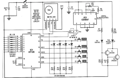
[image:3.612.105.509.437.699.2]The circuit diagrams for different units of the human detection robot are shown in fig 4.1, fig 4.2, fig 4.3, fig 4.4 and fig 4.5. In these circuits the transmitter and receiver units at remote control unit as well as robot setup is seperately shown. The four circuit diagram forms the entire human detection robot.
Technology (IJRASET)
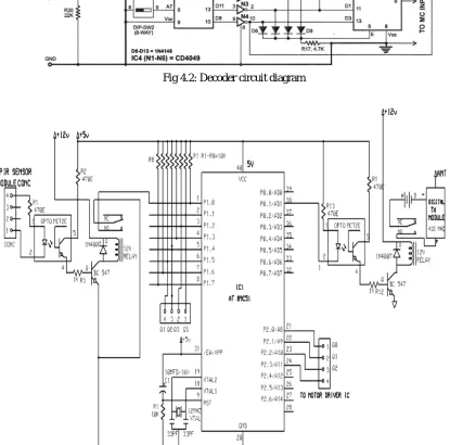
Fig 4.2: Decoder circuit diagram
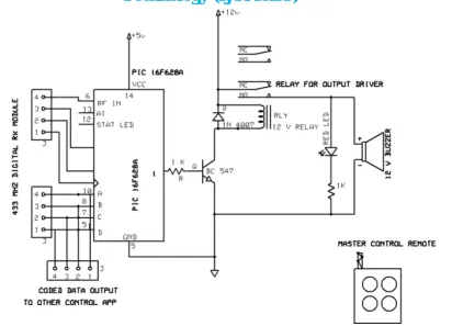
[image:4.612.96.511.259.669.2]Fig 4.4: Receiver circuit diagram at the remote control unit
Fig 4.1 indicates the circuit diagram for transmitter section at the remote control unit. The circuit consists of an encoder HT12E employing RF as well as IR principle. The circuit contains five push button keys to control the robot movement. They are forward, backward, left, right and stop. Identical address is selected on the encoder, when any of the switches on transmitted (marked as FWD, REV, RIGHT, LEFT) is pressed.
Forward: The D8 output (pin10) of IC3 goes low, which, after inversion by inverter N1 goes high to switch on the front LEDs (LED2 and LED3) via driver transistor T6 and take D3 input (pin 13) of IC5 high. This causes Q2, Q1 and Q0 going to logic states ‘0,’ ‘1’ and ‘1,’ respectively(and as a result, both the motors will run in such directions as to move the robot in forward direction. Reverse: The D9 output (pin 11) of IC3 goes low, which after inversion by inverter N2 goes high to switch on the rear LEDs (LED4 and LED5) via driver transistor T7 and take D4 input (pin 1) of IC5 high. This results in Q2, Q1 and Q0 going to logic states ‘1,’ ‘0’ and ‘0,’ respectively and as a result, both the motors will run in such directions as to move the robot in reverse (backward) direction. Left: The D10 output (pin 12) of IC3 goes low, which after inversion by inverter N3 goes high to switch on the left blinking LED7 after a second inversion by inverter/driver gate N6 and makes D2 input (pin 12) of IC5 high. This results in Q2, Q1 and Q0 going to logic states ‘0,’ ‘1’ and ‘0’ , respectively and as a result, only the right-hand-side motor will run and the left-hand-side motor will be static. This causes the robot to perform a left turn.
Right: The D11 output (pin 13) of IC3 goes low, which, after inversion by inverter N3 goes high to switch on the right blinking LED6 after a second inversion by inverter/driver gate N5 and makes D1 input (pin 11) of IC5 high. This results in Q2, Q1 and Q0 going to logic states ‘0,’ ‘0’ and ‘1,’ respectively and as a result, only the left-hand-side motor will run and the right-hand-side motor will be static. This causes the robot to perform a right turn.
Stop: The D8 through D11 outputs of IC3 go high and, after inversion by inverters N1 through N4, cause blocking of diodes D5 through D8. As a result, ground is extended to EI pin 5 through resistor R17 and all the outputs (Q2, Q1 and Q0) of CD4532 go low to stop both the motors. Also all the LEDs stop glowing.
Technology (IJRASET)
POWER ON RESET circuit.For this the reset pin must be kept in logic high level for some time and this logic high legel must be removed after some time. An RC network can satisfy this requirement. The R-C network is connected across the power supply rails. And the mid-point of the RC network is connected to the RESET pin of the micro-controller. For manual reset function a push-switch is connected across positive rail RESET pin.The timing clock is generated with the help of a crystal. The both ends of the crystal are connected to the X1 and X2 pins [18 and 19] of the AT 89C51. Typically, a quartz crystal and capacitors are employed. The crystal frequency is the basic internal clock frequency of the micro-controller. The manufactures make available 89C51 designs that can run at specified maximum and minimum frequencies, typically 1MHZ to 16MHZ. Minimum frequencies imply that some internal memories are dynamic and must always operate above a minimum frequency or data will be lost.
The relay switching circuit consists of BC 547 NPN transistor as electronic switch and a 12V/1C the relay. The base of transistor is connected to output of opto-coupler via 1K limiting resistor. The emitter is connected to ground and collector connected to one coil terminal of relay. The second coil terminal of relay is connected to +12V DC directly. If PIR sensor detect human body the output port of microcontroller goes low and activate the relay circuit and switch on digital transmitter module. A buzzer alarm and an LED indication will be produced at the receiver unit of remote control due to the action of PIC microcontroller for a human detection.
[image:6.612.107.520.268.711.2]B. Working
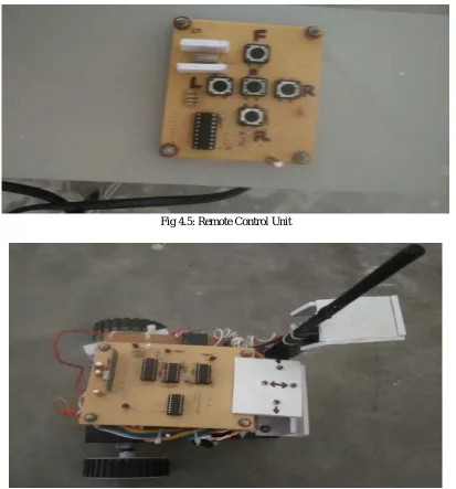
Fig 4.5: Remote Control Unit
movement. The signal produced due to the key press is transmitted and is received by the receiver placed at the robot unit and fig 4.6 represents the robot unit. There is a passive infrared sensor (PIR sensor) connected in front of the robot setup. During the motion of robot if the PIR sensor detects the human presence, then it would send a signal to the relay driver which gets energised and it activates an optocoupler connected to it. An alarm and an led indication will be produced for the human detection. Also a camera is provided at the robot unit so that the robot movement can be viewed through a screen at the control room.
IV.CONCLUSIONS
The application of wireless sensor network will improve the saving of many precious lives. The project is an efficient method for rescue operations and also for terrorists and thieves detection inside a building. As it is a wireless robot it can be easily mobilized and controlled.The application of wireless sensor network can realize the real-time monitoring of affected area by the natural calamities. The robot can be improved by using high range sensors and high capacity motors. Some more sensors like mobile phone detector, metal detector etc can be implemented to make this robot more effective.The project is useful to understand designing, programming and hardware implementaion of both ATMEL and PIC microcontroller embedded systems.
REFERENCES
[1] Seiji Miyama, Michita Imai, and Yuichiro Anzai, “Rescue Robot under Disaster Situation: Position Acquisition with Omni-directional Sensor”, IROS 200 , Oct. 2003, vol.3, pp. 3132 - 3137.
[2] Trupti B. Bhondve, Prof.R.Satyanarayan , Prof. Moresh Mukhedkar, “Mobile Rescue Robot for Human Body Detection in Rescue Operation of Disaster”, IJAREEIE, Vol. 3, Issue 6, June 2014
[3] Hardeep Pal Sharma,Guna sekar.C.H, S.Adithya Kumar , “Live Human Detecting Robot for Earthquake Rescue Operation ”, International Journal of Business Intelligents ISSN,June 2013, Vol 02, Issue 01 : 2278-2400
[4] Sandeep Bhatia, Hardeep Singh Dhillon and Nitin Kumar “Alive Human Body Detection system using an Autonomous Mobile Rescue Robot”, IEEE Transactions ,Vol 11, No 2, March 2011.
[5] Steve Burion, “Human Detection for Robotic Urban Search and Rescue”, Info science database of the publications and research reports,February, 2004. Record number 29999
[6] Donoso-Aguirr, “Mobile robot localization using the Hausdor Distance”, ROBOTiCA, Cambridge University Press, vol. 26, pp. 129-141, [7] Amerada, T., Yams, T., Igarashit, H., Matsunos, “Development of the Snake-like Rescue Robot KOHGA”, IEEE, 2004, PP. 5081-5086