Technology (IJRASET)
Analysis of an Industrial Building
Laxmi R. Gupta1, Samruddhi S. Thawari2
Assistant Professor, Department of Civil Engineering
Abstract- Structural Steel is a common building material used throughout the construction industry. Its primary purpose is to form a skeleton for the structure, essentially the part of the structure that holds everything up and together. Steel is one of the friendliest environmental materials which is 100% recyclable. Structural design has evolved, mostly due to the necessity caused by earthquakes. By using the available ISMB steel sections the desired design requirements cannot be met, especially for the highly loaded structures, as the moment of inertia and cross sectional play major role. Reinforced concrete sections also carry the ultimate load but when the assembly is subjected to great height of about 50-60 meters it is unsuitable for the use of concreting processes, thus by using the fabricated structure it is easy to fabricate durable structure.However, like all innovations, technology breeds its own set of new problems. So by the use of STAAD-Pro, seismic analysis is easily carried out with adequacy. Keywords- Ductility , Horizontal displacement, seismic forces
I. INTRODUCTION
High rise steel buildings account for a very small percentage of the total number of structures that are built around the world. The majority of steel structures being built are low–rise buildings, which are generally of one storey only. Industrial buildings, a subset of low-rise buildings are normally used for steel plants, automobile industries, utility and process industries, thermal power stations, warehouses, assembly plants, stores, garages, small scale industries, etc. These buildings require large column free areas. Hence interior columns, walls, and partitions are often eliminated or kept to a minimum. Most of these buildings may require adequate head room for the use of an overhead travelling crane.
The evolution of structural steel design brought us from the theory that the stiffer the structure the better. Today, flexibility and ductility are the key issues. The days of drafting are almost gone and digitizing the structure in the computer saves time, ensures quality and usually results in a lower cost.
II. BRIEF LITERATURE REVIEW
1. Dr. S.K. Dubey et.al.(1)in his paper indicated that to analyze the steel roof truss under the normal permeability condition of wind according to Indian Standard Code IS: 875(Part 3)-1987, in which, intensity of wind load is calculated considering different conditions of class of structure,Terrain, height and structure size factor, topography factor, permeability conditions and compare the results so obtained with the calculations made in SP-38(S&T):1987. Because of this, there are large variations in calculated results for wind loads and design forces in members of truss. Analysis of trusses called A-shaped truss is addressed.
2. K.G. Bhatia (2)in his paper explained theImprovement in manufacturing technology has provided machines of higher ratings with better tolerances and controlled behaviour .These machines give rise to considerably higher dynamic forces and thereby higher stresses and, in return, demand improved performance and safety leaving no room for failures. This paper highlights need for a better interaction between foundation designer and machine manufacturer to ensure improved machine performance. The paper also describes the design aids/methodologies for foundation design.
Technology (IJRASET)
[image:3.612.115.482.36.708.2]III. FINDINGS OF THE STUDY
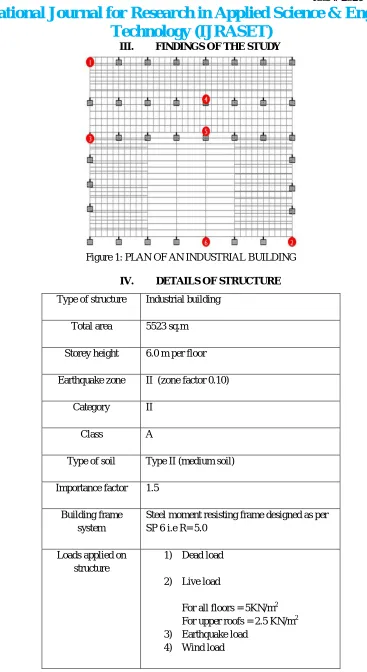
Figure 1: PLAN OF AN INDUSTRIAL BUILDING
IV. DETAILS OF STRUCTURE
Type of structure Industrial building
Total area 5523 sq.m
Storey height 6.0 m per floor
Earthquake zone II (zone factor 0.10)
Category II
Class A
Type of soil Type II (medium soil)
Importance factor 1.5
Building frame system
Steel moment resisting frame designed as per SP 6 i.e R= 5.0
Loads applied on structure
1) Dead load
2) Live load
For all floors = 5KN/m2 For upper roofs = 2.5 KN/m2 3) Earthquake load
Technology (IJRASET)
Following Graphs From Figure indicates the variation in displacement, force, and moment along X direction floorwise for various load combinations for six different columns.
Col1.Back side Left corner
Col2. Front side Right corner
0 5 10 15 20 25 30
-2 0 2 4 6
1.5(DL+LL)
1.2(DL+IL+EQX)
1.5(DL+EQX)
1.2(DL+IL+WLX0)
1.5(DL+WLX0)
Variation in X Displacement Floorwise
Displacement in mm
Technology (IJRASET)
Col2. Front side Right corner
Col1.Back side Left corner
Col2. Front side Right corner
0 5 10 15 20 25 30
-0.2 0 0.2 0.4
1.5(DL+LL) 1.2(DL+IL+EQX)
1.5(DL+EQX)
1.2(DL+IL+WLX0) 1.5(DL+WLX0)
Variation in Moment Mx Floorwise
Moment in KNmm
F
lo
o
r
H
e
ig
h
t
in
Technology (IJRASET)
V. CONCLUSION
A. Analysis and design as grids result in lower beam sizes.
B. Precautions in fabrication and erection can be taken on the site.
C. Higher resistance to the seismic forces occurred in the flexible frame structure by steel fabrication.
D. The bars having yield strength higher than 500N/mm2tend to possess lower percentage elongation which is not acceptable for Seismic prone structures.
E. The sectional properties for ISMB 900 section are not in database and design parameters of Staad.pro 2007 so by using the section as ISMB 600 resist the permissible stresses and the respective bending moments in beam sections.
REFERENCES
[1] P.J. Moss.2009.Design of steel portal frame buildings for fire safety. Journal of Constructional Steel Research. Vol-65, pp:1216-1224.
[2] Mahendrakumar. 2009. Elastic buckling of i- beam flanges subjected to a linearly varying stress distribution. Journal of Constructional Steel Research. Vol-63, pp:1373-1383.
[3] Maria Gabriella Mulas. 2003. A structural model for panel zones in non linear seismic analysis of steel moment- resisting frames. Journal of Constructional Steel Research. Vol-26, pp:363-380.