2018 International Conference on Information, Electronic and Communication Engineering (IECE 2018) ISBN: 978-1-60595-585-8
Design and Implementation of an Extensible Entire Component Virtual
Battlefield Electromagnetic Situation Display System
Zheng-hao SUN
1,2,*, Li-min YANG
2and Xin LIAO
1,2 1Aerospace System Development and Research Center, China Aerospace Science and Technology Corporation, Beijing 100094, China
2
R&D Center, China Academy of Launch Vehicle Technology, Beijing 100076, China
*Corresponding author
Keywords:Extensible entire component, Battlefield situation display, Virtual reality.
Abstract. In the research of virtual battlefield electromagnetic situation display system, the traditional methods were mainly used 3D simulation modeling software to realize visual scene. The disadvantages are that the developed system is not universal; the codes cannot be controlled independently as it is restricted by the permission of commercial software; the constant updating of business software versions makes it difficult to migrate development results. As a result, the system development process is complex; the code is not controlled; and the development results have poor inheritance. This paper presents a design idea of developing a virtual battlefield electromagnetic situation display system by using software platform with self-developed extensible entire component structure. The platform has a good secondary development interface and easy to extend application components, making the development process of electromagnetic situation display system simple, strong commonality, and the final show effect closer to real battlefield environment.
Introduction
According to the characteristics of traditional virtual reality 3D simulation software, this paper independently developed a software platform system with good secondary development interface and easy scalability. It can provide a unified support platform for virtual reality environments and a range of applications in a range of related fields. In this paper, it was used to develop the three-dimensional display system of the battlefield electromagnetic situation with multi-level and high-definition.
Concept and Description of Battlefield Electromagnetic Environment
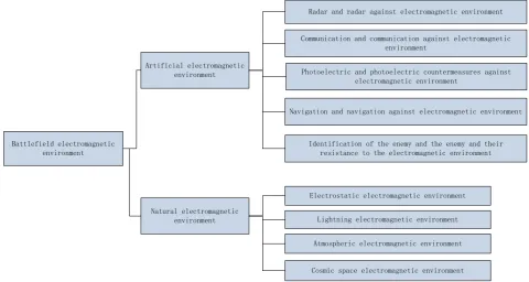
The battlefield electromagnetic environment refers to the sum of all electromagnetic phenomena in a certain combat time and space, including artificial electromagnetic emission and natural electromagnetic phenomena. It is with the characters of continuous duration, spatial crisscross, dense overlap in the frequency domain, up-and-downs of the energy domain, and a wide variety of waveform styles.
Battlefield electromagnetic environment
Artificial electromagnetic environment
Natural electromagnetic environment
Radar and radar against electromagnetic environment
Communication and communication against electromagnetic environment
Photoelectric and photoelectric countermeasures against electromagnetic environment
Navigation and navigation against electromagnetic environment
Identification of the enemy and the enemy and their resistance to the electromagnetic environment
Electrostatic electromagnetic environment
Lightning electromagnetic environment
Atmospheric electromagnetic environment
[image:2.595.56.537.262.518.2]Cosmic space electromagnetic environment
Figure 1.Composition of the battlefield electromagnetic environment.
The basic elements of the battlefield electromagnetic environment mainly include the battlefield environment, the background environment, and the operational platform equipment signal environment. The description for the battlefield environment is due to the description of the terrain, geomorphology, climate and atmosphere. Geographical environmental factors in the battlefield area also have a direct impact on the propagation of the electromagnetic environment, resulting in complex features of the electromagnetic environment. The combat platform equipment signal environment is the main body of the electromagnetic environment. It is also a direct determinant of the spatial distribution characteristics and dynamic characteristics of complex electromagnetic environments. The description of combat platform is mainly from the aspects of platform location information, platform attribute information, information on the source of radiation, working system, and information on the source of interference.
loading, resource management, and event processing distribution are encapsulated in the service as a framework. Scene management, terrain organization, collision detection, and resources of multiple data types are encapsulated into interfaces placed in the platform interface definition. When the module uses the scene and terrain, it is referenced through the defined interface, and the corresponding resource implementation can be added to the new data format at any time [4,5].
The mechanism of message event distribution makes the modules loosely coupled, so that the remote client can modify the scene as if it were a local operation. As long as the functional modules that implement the initialization and cleanup interfaces defined by the base platform can be accessed. This feature makes the system more open and easy to extend the functionality of the entire system.
The openness of the system allows other existing systems to be ported as a functional module on the underlying platform with only a small amount of code modification. The form of the base platform plus the plug-in function module facilitates the cutting of unnecessary functional modules, and facilitates the selection of a suitable functional module assembly system as needed.
The Overall Design of the Virtual Battlefield Electromagnetic Situation Display System
Functional Requirements
A complete battlefield electromagnetic situation display system includes 3D scene construction and electromagnetic space environment construction. Then add a physical battle model to the scene to add electromagnetic behavior to the model. The data drive of the model is realized through script control, and the control of the operational process and perspective is realized by using the UI interface. The human-computer interaction function can realize the zooming of the map, the hierarchical display of the terrain data, the query of the information, the switching of the viewing angle, and the special effect display of the corresponding entity can be triggered through the interface operation.
Specific battlefield electromagnetic behaviors include: a) Action area
The active area of the device can be displayed in terms of power and angle range. b) Target Detection
The real target and the detected target after the interference can be displayed in different colors, and the accuracy is reduced or even lost after directly seeing the interference.
c) Track offset
The ideal trajectory and the disturbed trajectory can be displayed in different colors, and the trajectory offset after interference can be directly seen.
d)Strike effect
Demonstration of the fuze after being disturbed cannot hit the target. e) Faction attribute
After the enemy and the identification system are disturbed, the enemy and the enemy properties of the entity change.
f) Data link
After the analog data link is disturbed, the effect of the chain cannot be established between entities.
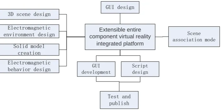
Development Process Design
Extensible entire component virtual reality
integrated platform 3D scene design
Electromagnetic environment design
Solid model creation Electromagnetic behavior design
GUI design
Scene association mode
GUI development
Script design
[image:4.595.111.471.78.257.2]Test and publish
Figure 2. Overall development process of battlefield situation display system.
Firstly, use the large terrain-editing tool in the support platform to create a three-dimensional terrain model with real geographic image remote sensing data. It is necessary to construct a global three-dimensional scene and construct a local battlefield shape with a typical engagement area;
Use 3DMax to create the required solid unit in the scene, and import the terrain and entity model into the platform;
Create an electromagnetic environment with the electromagnetic environment planning module in the platform, select the electromagnetic environment simulation action point by observing the viewpoint, and complete the pulse full parameter and signal feature setting by the radiation source editing;
Use the scene development tool of the platform to perform scene association, and use C# to develop script files to realize physical action interaction, electromagnetic behavior representation and scene control;
Use the physics engine of platform to add special effects displays to the battlefield actions triggered by the participating physical units;
Finally, Design the GUI human-computer interaction interface, and the testing and release of the product is completed.
Implementation of Virtual Battlefield Electromagnetic Situation Display System
Terrain Scene Creation
The first step in setting up the scene is about the construction of the battlefield landscape, which is also the carrier of the other models in the entire scene. Before other models are established, the terrain of the scene should be planned reasonably, and the overall contour should be established through the requirements. A special feature of the platform that can extend the full-component structure is that as long as the landform is more than 75% developed, the platform can fill the rest of the platform by itself, thereby improving the development efficiency of the developer. In the real environment, the terrain is uneven and irregular. Here, in order to simplify the calculation method and improve the rendering speed, an approximation algorithm is used to fit the surface of the Gaussian curve to simulate the fluctuation of the natural terrain [6].
Electromagnetic Environment Creation
electromagnetic signal environment generating device, the distance and angle change matching with the related device, and the matching of the radiation source antenna characteristics.
Table 1. Electronic equipment modeling.
Active radar Passive radar Secondary radar Relay
communication
Missile fuse
Active head
Passive head GPS/ Land-based
navigation
— —
Ground warning Early warning
radar — Interrogator —
Aircraft Airborne radar GPS navigation
Interrogator Answering
machine
Data link
Early warning
machine Airborne radar GPS navigation
Interrogator Answering machine Data link Ship Sea radar Airborne radar Fire control radar
Anti-collision radar GPS navigation Interrogator Answering machine Data link Satellite Active reconnaissance radar Passive reconnaissance
radar formation Telemetry remote Relay forwarding
Participation Entity Creation
The battle model is the main carrier of the scene information. The model needs to be 3D modeled by 3DMax 3D production software, and then imported into the virtual reality integrated support platform with scalable full component structure in .fbx format. The 3D model currently received by the platform is mainly in the .fbx format, and its maximum use is to use the mutual guidance of models, materials, motions and camera information between software such as 3Dmax and Maya. Simple basic objects (such as trees, flowers, etc.) can be created directly in the platform, and specific models related to actual combat applications (missile, satellite, aircraft, ship, etc.) need to be created by 3D software such as 3DMax. The unit in the platform defaults to 1cm, and the ratio of the 3DMax import platform is 0.01:1. Before the model is created, the model size planning operation is required. For the model, the number of patches is better than 32,500.
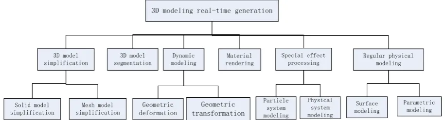
3D modeling real-time generation
3D model simplification 3D model segmentation Dynamic modeling Material rendering Special effect processing Regular physical modeling Solid model simplification Mesh model simplification Geometric deformation Geometric transformation Particle system modeling Physical system modeling Surface modeling Parametric modeling
[image:5.595.68.526.559.683.2]Figure 4. Solid model creation effect.
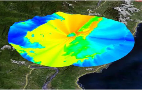
Electromagnetic Characteristic Drawing
The calculation of the single-point electromagnetic characteristic is to calculate the field strength at any point in the radiation field, including the radiation source loss calculation part and the composite field strength calculation part of the point. The single-point electromagnetic calculation module is mainly responsible for calculating the electromagnetic field strength of each point in the radiation field generated by the radiation source. The module consists of four parts: space electromagnetic intensity input parameter, radiation source antenna arrival area, electromagnetic radiation accuracy and real-time performance, and radar radiation source power range. The electromagnetic field drawing module is responsible for drawing the electromagnetic field under the specified parameters, and using different colors to assign different strengths of the electromagnetic field, thereby completing the electromagnetic field drawing work. The module mainly uses the illumination model in the volume rendering technique to plot the radiation intensity of the electromagnetic field [7].
Figure 5. Drawing of the overall electromagnetic properties of the battlefield.
Human-computer Interaction Interface Design
[image:6.595.147.449.461.653.2]means that the programmer can easily extend the functionality of the plugin and tweak existing functionality. For other users, it is higher performance and lower learning difficulty.
Test Verification
[image:7.595.142.455.225.399.2]Based on the self-developed virtual reality integrated support platform of extensible entire component structure, this paper designs a battlefield electromagnetic situation display system, and completes the real-time rendering of battlefield scene, electromagnetic environment, physical target and special effects action. The system running platform is Windows 10 operating system, and the graphics card is NVIDIA Quadro M6000 (12GB GDDR5). The three-dimensional battlefield panorama is as follows:
Figure 6. 3D battlefield global situation.
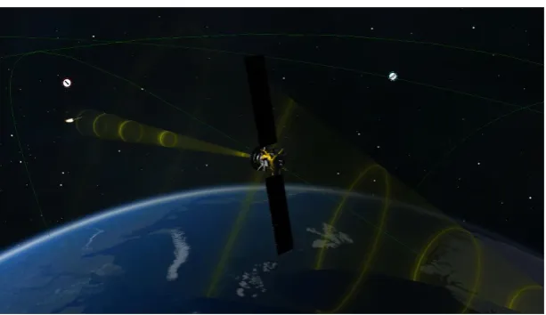
Figure 7. Satellite communication link.
Conclusion
[image:7.595.145.452.419.596.2]References
[1] Wang Wei. A Study on U.S Army's Range Development Modes. National Defense Science & Technology, 2008(2).
[2] Zhang Yang, Shi Chuan. Design and Implementation of Radar Electromagnetic Environment Simulation System in Aerial Battlefield. Fire Control & Command Control, 2015(10):172-177.
[3] Yu Hui. Complex Electromagnetic Environment Effects on EW Operational Command System. Electronic Warfare Technology, 2009(5).
[4] Li Hu, Wu Jiazhu. Research and Realization of a Battlefied Situation System Based on Skyline. Computer Engineering and Science, 2009, 31(4):26-28.
[5] Hu Hongbo. Architecture and Techniques of Common Operational Situation Picture. Command Control & Simulation, 2006.
[6] Wang Bo. Design and Implementation of 3-D Situation Display System for Virtual Sea Battlefield. Journal of System Simulation, 2012, 24(1):214-218.