309
Improve Manufacturing
Validation
During
Product
Development
Patrick C.
Hammett,
1
Shannon M. Wahl andJay
S. BaronUniversity
ofMichigan,
2901 Baxter Road, Ann Arbor, MI 48109, USAReceived 23 August 1999; accepted in revised form 30 October 1999
Abstract: In order to improve engineering product designs and reduce the number of problems that occur during a new product launch,
firms have focused on integrating downstream product development processes into the design phases. Unfortunately, this resource
inte-gration to solve problems has been less common in the back-end of product development, particularly for complex products involving many components such as an automotive body. Here, manufacturing firms use sequential validation procedures first to approve compo-nents, then subassemblies, and finally the end product. One trend has been to tighten component tolerances in efforts to avoid or mini-mize downstream assembly problems. These stricter component requirements, however, often result in timing delays and cost overruns
due to unnecessary rework of components. For complex-assemblies, the use of "flexible criteria" and an approach called "functional build" can significantly reduce validation time and costs yet still meet end product quality objectives. This paper examines this functional build approach to manufacturing validation and demonstrates its effectiveness with an automotive case example.
Key Words: manufacturing validation, process capability, automotive bodies, integrated product and process development, metal stamp-ing, tolerances.
1. Introduction
As
product
lifecycles
shorten, manufacturersplace
agreater
emphasis
on newproduct development.
These efforts have lead to reductions in costs and lead time. Aprincipal
driver of these
improvements
has been more effectiveinte-gration
ofdevelopment
resources into theproduct
and pro-cessdesign phase
through
practices
such as concurrentengi-neering, design
formanufacturability,
andpartnership
sourcing
[ 1-3].
This resourceintegration,
however, has beenfar less common in the back-end of
product development.
During
thisphase,
manufacturers oftenattempt
to execute asequential
validation processwhereby
they
first try to&dquo;buyoff’
or approve all individualcomponents.
Oncecom-ponents are
approved,
manufacturers then validatesub-as-sembly
and finalassembly
processes. Thissequential
ap-proach
subscribes to the basicparadigm
that finalproduct
quality
is maximized if the mean of each individual compo-nent dimension isproduced
to itstarget
specification
with minimal variation.In
practice,
few manufacturers execute asequential
pro-cess validationapproach
where finalassembly
validationstarts on schedule with all component
quality requirements
met.
Instead,
manufacturers either startassembly
validation withnon-approved
components
ordelay
the start of valida-tion asthey
wait forsuppliers
to resolvenon-conforming
is-sues or
incorporate
lateengineering changes.
Costsassociated with these
delays
often follow a Paretoprinciple
wherereworking
10-20%of component
dimensions mayac-count for 80-90% of the total late time. The effects of these
delays
often becomecompounded during
finalassembly
val-idation as manufacturers discover newassembly problems,
resulting
in additional rework of components. In addition,some of the
non-conforming
issues worked onduring
com-ponent
validation are later found to have minimalimpact
onthe final
assembly, questioning
theimportance
ofmeeting
theoriginal
criteria.Although
betterintegration
of resourcesinto the
design
phase
cansignificantly
reduce the number ofproblems
in the back-end ofproduct development,
problems
still arise.Thus,
the effectiveness ofidentifying
andresolv-ing manufacturresolv-ing
validationproblems
becomes critical tothe overall costs and time to launch a new
product.
The effectiveness of
manufacturing
validation oftende-pends
on theability
todevelop
criteria andprocedures
thatseparate
realproblems
from those non-conformities that donot affect the end
product.
At times, manufacturers ofcom-plex products
over-focus their validation efforts onmeeting
component
requirements
to the detriment ofvalidating
the fi-nalproduct. They
reworkcomponent
features thatslightly
deviate fromdesign
intentonly
to discover moresignificant
problems
whenthey
assemble thecomponents.
Unfortu-nately,
if component suppliers
are notmeeting
all theoriginal
quality requirements,
they
become easytargets
to blame forproduct
launchproblems.
As aresult,
suppliers
continue torework their
components
even when some of the non-confor-mities have a low likelihood ofaffecting
the finalproduct.
In efforts to minimize
problems during manufacturing
val-idation of the endproduct, companies
oftentighten
compo-nent
requirements
inattempts
tolegislate betterquality. They
assign
these stricterrequirements
ondesign prints
withoutdemonstrating
that their processes have theability
tophysi-cally
meet them. In contrast to thisapproach,
this paper will show that for manycomplex product
assemblies, manufac-turers maysubstantially improve
the effectiveness of theto-tal
manufacturing
validation processthrough
looseiring
rather thantightening
component
requirements.
Critical tothis
strategy
is theintegration
ofproduct
and processdesign
resources forward into the
manufacturing
validationphase
of newproduct development.
Oneapproach
toexecuting
this strategy isthrough
a process known as functional build.Un-der functional build, component
suppliers
arerequired
tofirst get their
products
withindesign
windows, but notneces-sarily
achieve 100%compliance
for all part characteristics. Manufacturers then use downstreamassembly
validationprocesses to determine which component non-conformities
must be reworked to build an
acceptable
finalproduct.
Thisstrategy will be demonstrated
using
several case studies ofthe
development
of automotive bodies.2. Problem Identification and Resolution Processes
One guarantee in
manufacturing
validation is thatprob-lems will arise. Parts and processes will have
design
errors;part dimensions will be
produced
out-of-specification;
as-sembly
processes will be unable: to assemble certaincompo-nents. These
problems
often relate to a lack ofunderstanding
of
component-assembly
buildrelationships
and thedifficul-ties in
assigning
aproduct
specification
[4].
Productspecifi-cations
usually
consist of a target value(desired
measure-ment)
and a tolerance. The tolerance represents the al lowabledeviation from the target in which the
designer
believes theproduct
may vary and stillyield
anacceptable assembly.
Twocommon
problems
withassigning product specifications
areincompleteness
andover-specification
[3]. Incompleteness
is the failure to
identify
all criticalfeatures;
over-specifica-tion occurs when manufacturers try to minimize their
down-stream
assembly problems by
requiring
that theirsuppliers
(in-house
orexternal)
meetunrealistically
narrowtoler-ances.
Unfortunately,
the real effect of notmeeting
acompo-nent target or tolerance may remain unknown until
assembly
process validation.
To minimize
assembly
validationproblems,
most of theproduct development
research describes methods used toprevent
problems
fromoccurring
in the firstplace.
Theprin-cipal
strategy
proposed
to minimize downstreamproblems
isintegrated product development.
Many
researchers have noted the benefits ofintegrated product development
onquality, timing
and cost[5,6].
Forinstance,
Ettile[7]
demon-strates the
relationship
betweenintegrated product
develop-ment and
product quality improvements,
both in terms ofspecification
conformance and customer satisfaction.How-ever, no matter how well
designed
aproduct
is,
problems
will occurduring
aproduct
launch. Given thisreality, companies
must
effectively identify
and resolveproblems,
withoutex-pensive
process rework. Problem identification andtechno-logical learning,
likeproblem
avoidance, also has been the focus ofproduct development
research.Problem identification and resolution is linked to a firm’s
ability
toacquire
technological knowledge
during
aproduc-tion ramp-up. Bohn
[8]
develops
aneight-stage
frameworkfor
measuring
andmanaging technological
knowledge
ofmanufacturing
processes and notes that noise inmanufactur-ing
processes may reduce the rate oftechnological learning,
thusprolonging
theproduct
development
and launchstages.
In another paper, Jaikumar and Bohn[9]
relate the stages ofknowledge
to aproduct
launch.They
discuss how theeffec-tiveness
of pilot
lines may be reduced whenknowledge
aboutthe component parts and processes used to assemble a
prod-uct is low. For
example,
if a firm attempts to resolve aproduc-tion
problem by tightening
tolerances on a component aboutwhich
knowledge
isrelatively
low, interactions amongpeo-pie,
machines and other components that werepreviously
unimportant
may becomesignificant
and causeproblems
greater
than theoriginal
one.To
acquire technological knowledge during
manufactur-ing
validation,
firmstypically
use eitherlearning by
experi-mentation or
in-process learning. Upton
and Kim[ 10]
notethat many firms become locked into one of these two meth-ods of
learning.
This limits theirtechnological knowledge
andability
to solveproduction problems.
Ward et al.[
1 1]
il-lustrate howToyota
attempts to avoidlocking
itself into onemode of
learning
by
delaying
the finalization ofspecifica-tions, in order to
incorporate technological
lessons learnedduring prototyping
into theoriginal design
wheneverpossi-ble.
Bhattacharya
et al.[4]
also examines the benefits ofde-laying
final customerspecifications through
a flexibleprod-uct definition process. Most of the models on
delaying
finalspecification
decisions focusprimarily
on the front-end ofproduct development-the
design
stage. A lessdeveloped
aspect has been indeveloping
executable, flexiblestrategies
for the back-end ofproduct development.
3. Process Validation
Criteria:
Cp
andCpk
The most common evaluation criteria used
by industry
toidentify problems
in components and assembliesduring
manufacturing
validation are the processcapability
indices,
Cp
andC~~
[ 12].
These indices measure theability
of apro-cess to
produce
parts within thespecified
tolerance width. This tolerance width(difference
between upper and lowerspecifications)
represents the allowable variation from aindex differs from
Cp
because it also considers the deviation of the mean from thetarget
(nominal)
specification.
TheCpk
k index becomesincreasingly
smaller thanC~,
the further themean deviates from nominal.
Manufacturers
typically assign performance
standards forCp
andCpk
that reflect desiredquality
levels in terms of de-fects. Forexample, achieving
aCpk>
1.67(hence
C~, >
1.67)
implies
apotential
toproduce
less than I defect per million.By
examining
both theC~,
andCpk
index, manufacturers may determine if theirproblems
relate to excess variation(fail
Cp)
orlarge
mean deviations(pass
Cp,
failCpk)-CP
andCpk
indices have becomewidely accepted
in many industries becausethey provide objective
criteria to evaluate the conformance of components to theirdesign
require-ments. Another
appeal
of these indices is theirsimplicity.
Since their values are relative to tolerances, their
interpreta-tion is the same for any measured part characteristic.
By
us-ing
CP
andCpk,
manufacturers mayassign
onegeneric
qual-ity
standard for all part measurement characteristics.Many
researchers have commented on thepotential
prob-lems
of using
processcapability
indices. Theirconcernstypi-cally
relate to theunderlying
statisticalassumptions
such asnormality
andsample
size incalculating
these indices[ 13]
aswell as the
tendency
to relateC~,
andCpk
toarbitrary
lossfunctions,
for whichthey
were not intended[ 14].
In additionto these statistical concerns, process
capability
indices alsohave limitations in
identifying quality problems during
man-ufacturing
validation.The effectiveness
of using
theC,,k
index formanufacturing
validation oftendepends
on theability
toadjust
meandimen-sions. Consider the situation
presented
inFigure
1 where apart characteristic has low variation
(passes
C~,)
but failsCpk
due to a mean deviation. For processes such asmachining.
manufacturers may
inexpensively
shift this mean to nominalby adjusting cutting
tools.For example,
in a verticalmachin-ing operation,
operators
mayadjust
thepositioning
of acut-ting
tool up or down to shift a part dimension to its targetspecification.
For many processes, however,
simple adjustment
factors like these do not exist. In the case of dies ormolds,
manufac-turers
usually
mustphysically reshape
the tools toadjust
a mean dimension.Furthermore,
rework for these processes [image:3.559.25.260.622.723.2]often is inexact. In the case of
stamping
dies,
metal willFigure 1. Example of a dimension with stable variation but off
tar-get.
spring
back once the component is released from the die. For other part characteristics, manufacturers havedifficulty
pre-dicting
the metal flowduring forming opcrations.
These dif-ficulties arecompounded by interrelationships
betweenma-tcrial
properties,
dies and partdesigns.
In some cases,reworking
a process to shift one part characteristic closer totargct may
adversely
affect another.The
principal
concerns with thesedifficult-to-adjust
pro-cessesduring manufacturing
validation are excessive reworkcosts and
longer
lead-times. In the case of automotivestamped
parts. 20% of the cost of themanufacturing
dies may be attributed to rework[ 1 S].
Whenconsidering
all thecom-ponents within a vehicle, the total rework cost may reach $20 million. Even with this extensive rework, automotive
body
manufacturersroutinely begin asscmbly
validation with component mean dimensionssignificantly deviating
fromtarget
speci ications.
Cost and lead-time concerns
resulting
fromreworking
components to meetcpk
requirements
becomeparticularly
disconcerting,
if a manufacture,- discoversduring
finalas-sembly
validation thatachieving
Cpk
requirements
forcertain characteristics was unnecessary. As mentionedpreviously,
product
designers
willover-specify
componentrequire-ments to reduce the risk of downstream
assembly
problems.
Theflip
side of thisapproach
is that manufacturers willre-work components
during manufacturing
validation to meetunnecessarily tight
tolerances.One effect of
assigning
unrealistic tolerances is that thefi-nal
specifications
for componentquality
characteristicsbe-come
negotiated during
manufacturing
validation. As launchdates near, manufacturers will
negotiate
new, attainableto]-erances with
designers
so that all component dimensionsmeet a
quality
standard such asCpk>
1.33. This tolerancene-gotiation
is notnecessarily
a system flaw but amanufactur-ing reality. Unfortunately,
manufacturersusing
processca-pability
indices such asC~,
andCpk
often view tolerancemodifications as a last resort rather than a normal
activity
within the
manufacturing
validation process.They
continueto rework processes until
they
run out of time and thenthey
ask for tolerance
adjustments.
The fact thatthey ultimately
produce
endproducts
that meet customerrequirements
withsome individual component dimensions not
meeting
theiroriginal specifications
indicates apotential
to avoidunneces-sary rework. If a
non-conforming
component feature doesnot affect the
quality
or function of the endproduct,
atoler-ance
adjustment
to the partsignificantly
less thanphysically reworking
orre-designing
the componentpro-cess.
4. Case
Example:
Evaluating
the Effectiveness ofCpk
To
produce
an automotivebody,
manufacturers assemble1 SO-?00
stamped
components. Onechallenge
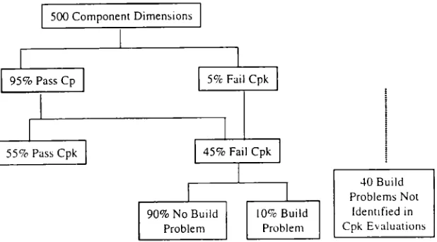
withev-Figure 2. Relationship between
assembly-build
problems andCPk
conformance.ery
part
dimension mean at its target.Ultimately, body
manu-facturers must address the effects of
off-target
meandeviations on assemblies
particularly
if the variation of thecomponent dimension is stable and meets
C~,
standards.Fig-ure 2 summarizes
Cp
andCpk
conformance and theirrelation-ship
toassembly
problems
for 500 dimensions on 30body
side components near the start ofmanufacturing
validation.Although
this manufacturer is able to meet the variationre-quirements,
Cp >
1.33, for 95% of the part dimensionsrela-tively
quickly,
they
have numerous mean dimensionsoff-tar-get
(45%)
resulting
inunacceptable
Cpk
values. [image:4.559.122.431.65.236.2]Rather than
reworking
all of these component dimensions untilachieving
Cpk,
this manufacturer evaluated the effect of each component mean deviation on theassembly
process.Figure
2 indicates that of the dimensionsfailing
C~,A
(225
outof
500),
only
10% related to actualassembly
buildproblems.
By
evaluating
these component features relative tomating
parts
and notsolely
based onCpk
standards, thismanufac-turer avoided unnecessary rework for 90% of the dimensions
that failed their initial
requirements. Interestingly,
thismanu-facturer did
identify
40 buildproblems
with thesecompo-nents that did not surface
using
Cpk
evaluations. These buildproblems
related todesign
errors(dimensions
metC~~
but did not assembleproperly)
and deviations in non-measuredareas of the part. For
complex
body
panels,
manufacturerscannot
realistically
measure everypossible point
on the part surface. As a result, someproblems
do not arise untilmanu-facturers
physically
assemble components.5.
Replacing
Cpk
with Flexible CriteriaMany
companies
useCp
andCpk
criteria to approvecomponents
forregular production.
These criteriaessen-tially require
variation conformance for allcomponent part
characteristics. Inprior
sections,
concerns were raised about the use of theseindices,
particularly
for hierarchicalas-semblies
involving
numerouscomplex
components. Theremainder of this paper discusses the
development
ofal-ternative validation criteria for
multi-component
assem-blies.
Specifications
for the final assembledproduct
are criticalbecause these
typically
have directrelationships
withcus-tomer satisfaction. In the case of an automotive
body,
cus-tomers expect a
parallel
gap between exteriorpanels
such asthe hood and fender. If the gaps have severe
out-of-parallel
appearances, customers may
perceive
apoorly
manufacturedproduct
and choose not tobuy
it. For endproduct
require-ments. the use ofC~~
provides
an effective tool to insureproduct
conformanceassuming
a reliable system exists to measure the feature and the tolerances reflect customerex-pectations.
For components within anassembly,
however,
determining appropriate
validation criteria is less clear. Forinstance,
external customersreally
do not care if componentcharacteristics are within their
original
tolerances(pass
Cpk)
provided
the finalproduct
isacceptable.
Although
external customers may not care,original
equip-ment manufacturers(OEMs)
oftenrequire
thatcomponent
suppliers
meetCpk
performance
standards for alldesignated
product
characteristics. Theirprincipal
argument
for strictCPA
compliance
is to reduce the risksof problems during
finalassembly manufacturing
validation.Unfortunately,
strict ad-herence toCpk
quality requirements
for components oftencreates another set of
problems
in terms ofhigh
rework costs andtiming delays
if asupplier
hasdifficulty meeting
the standards based on theoriginal
tolerances.Thus,
thefollowing recurring
situation occurs whensup-pliers
are latedelivering products. Suppliers
are late becausethey
are unable to meetCpk
objectives
for features thatthey
believe haveunnecessarily tight
tolerances. Assemblers,even if
they
agree that the tolerances are toostringent,
arere-luctant to approve
components
notmeeting
allCpk
objec-tives.
They
are concerned that if anassembly
problem
does occur,they
will be blamed foraccepting
thenon-conforming
components.
The safestposition
for assemblers is to demand thatsuppliers
meet alloriginal design
criteria.Ultimately,
however,
the decision processchanges
because of timenon-conforming
components and workclosely
withsuppli-ers to
only change
what is necessary toproduce
anacceptable
final
product. Ultimately
time pressures force value-added rework decisions.This low
assembly
riskapproach
involving
strictC~~
com-pliance
often becomessub-optimal
whenviewing
the back-end ofproduct development
as a total system. Manufacturersrecognize
thatcomponent
suppliers
often will not meet all theirCpk
requirements using
theoriginal design
tolerances.They
also know fromexperience
that certaincomponent
fea-tures
failing
Cpk
will not affect the finalproduct.
Thus, ifsup-pliers
reworkcomponents
basedstrictly
onCpk
criteria,
they
will
perform
unnecessary rework that will add cost and timeto the overall system validation.
Assemblers, however,
rec-ognize
thatthey
areessentially
absolved ofresponsibility
formost final
product quality
problems
aslong
as individual components are notapproved, making
them risk-adverse toearly
toleranceadjustments.
At the core of this conflict is the intent to executesequential
validation.By utilizing
flexible criteria to allow more concurrent component andassembly
validation, manufacturers can reduce total system costs and lead-time.One
approach
toadding flexibility
in component valida-tion criteria is to separate mean and variation conformance rather than combine them inCpk’
For instance, manufacturers would useC,
criteria to insure that the process variation isac-ceptable,
but notnecessarily require
that all mean deviations be centered at the target value. Forexample,
a manufacturer couldrequire
aCp
> 1.33 and a mean within the tolerancelimits
(as
opposcd
toclosely
near the targetvalue)
to startas-sembly
validation. Theflexibility
here is that meandimen-sions may
moderately
deviate from theoriginal
targetspeci-fication and some parts may be
produced
outside theoriginal
tolerance limits. Under this
approach,
manufacturers couldbegin assembly
validation sooner rather thantrying
tore-work a stable process to
improve
mean conformance. Thisapproach
recognizes
that somecomponent
features that passCp
but failC~~
may later be reworked based on theassembly
[image:5.559.32.229.572.729.2]build,
but other features mayonly require
a partadjustment.
Figure
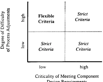
3. Flexible versus strict criteria.Under this
approach,
components arenearly
simulta-neously approved
with their assemblies. Thisapproach
rep-resents a tremendous
paradigm
shift fromsequential
valida-tion.
Interestingly, timing
pressures insequential
validationtypically
lead to simultaneous component andassembly
ap-proval
anyway as the deadlineapproaches.
Theadvantage
with thisapproach
is thatby using
flexible,
looser criteria for components, manufacturers may avoid many of thenon-value added rework decisions
trying
to meetCpk
criteria than when used as a last resort.The effectiveness of flexible criteria systems is not univer-sal to all
products.
Theiradvantages clearly
relate to certainprocess and
assembly
characteristics. Two of these factors are thedifficulty
inmaking
component processadjustments
(i.e.,
known meanshifts)
and thecriticality
ofmeeting
theoriginal
componentdesign requirements. Criticality
defined here relates to the robustness of theassembly
process tocom-ponent deviations,
the relative easeof changing mating
com-ponents,
and theability
to make downstreamadjustments
in theassembly
process. Forexample,
many downstreampro-cesses can compensate for a
non-conforming
mean of acom-ponent
by adjusting
anassembly
toolprovided
that thevaria-tion is stable.
Figure
3 compares the ease of component processadjust-ment and dimensional
criticality
with the use of eitherflexi-ble or strict criteria.
Again,
strict criteriaimply
thatcompo-nent
approval requires
that all characteristics meet theirquality
standardsusing
theoriginal
tolerances.Utilizing
flexible criteria entailsspecifying
looser component criteria and then near simultaneousapproval
of components
and tinal assemblies based on thequality
of the build and notnecessar-ily
conformance of component features toCilk
-If process
adjustments
arerelatively simple
(i.e.,
lowcost), then manufacturers should utilize strict criteria. There is no reason to increase
assembly
risk if manufacturers mayeasily
achieve theircomponent
requirements.
If thecritical-ity
ofmeeting
componentrequirements
ishigh.
manufactur-ers also should maintain strict criteria. The
assumption
here is thatnon-conforming
component features willultimately
require
rework untilthey
comply
withdesign requirements,
so little value exists in
delaying
rework until aftercompo-nents are evaluated in their assemblies. The use of flexible
criteria appears most
promising
if the component processad-justment difficulty
ishigh
and thecriticality
ofmeeting
theoriginal specifications
isrelatively
low.Although
thisrepre-sents
only
one of the fourquadrants,
itapplies
to manycom-plex
assemblies where the back-end ofproduct
development
presents
the greatestchallenge.
The next section discusses how automotive firmsapply
flexible criteria tomanufactur-ing
validation of thebody using
a functional buildstrategy.
6. Functional Build: A New
Paradigm
manufac-Figure 4. Parallel assembly of a non-rigid mating surface to a rigid reinforcement.
turing
validation ofstamped body
components. Underfunc-tional build, rather than
validating
components
solely
to their partprint specifications,
manufacturers also evaluatecom-ponents relative to their
mating
parts andsubsequent
assem-bly
processes. Manufacturers treatoriginal design
specifica-tions as
goals
rather than absoluterequirements.
Forexample,
if a manufacturerexperiences difficulty meeting
aparticular
componentrequirement.
they
may be able tore-solve the
problem
in a downstreamassembly
process orchange
another related,mating
component
moreexpedi-ently.
By
analyzing
components in theirsubsequent
assem-blies,
manufacturers may find that certainoriginal
require-ments are not critical to the final
product
build. Here, amodification to the
design print
is lessexpensive
thanphysi-cally changing already-constructed
manufacturing
tooling
such as a metalstamping
die.Functional-build type
practices
for automotivebody
vali-dation have existed for several years. The
principal
evalua-tiontool,
orscrew-body
process, may be traced to theearly
1970s to a process known as &dquo;screw and scribe.&dquo; Here,manu-facturers would screw
mating
componentstogether
to check forassembly
interference.Toyota
iterated on this processand
began using
it as an evaluation tool for componentre-work decisions.
Today,
severalcompanies including
General Motors andChrysler
[16]
use functional-build typestrate-gies.
Under functional
build,
manufacturers use the validation process todynamically
set tinal componentdesign
specifica-tions in accordance with the
capabilities
of the constructed processes.Suppose
a dimension has aCpk
of 0.52(tolerance
+-0.7 mm, mean = 0.5 mm, andCp
= 1.83mm).
If thisdi-mension results in an
acceptable assembly, they
would shift the target 0.5 mm and thenlaterally adjust
the tolerance from -0.2 to 1.2 instead ofreworking
the mean.(Note:
the totaltolerance width would remain 1.4
mm.)
In
delaying
finalproduct
specifications during
manufac-turing
validation,
one mustrecognize
the difference between&dquo;tweaking&dquo;
specifications
andmajor design changes.
In the aboveexample,
the overall tolerance width did notchange,
and the
target
only
shifted 0.5 mm(which
isrelatively
minorfor automotive
body assembly
ofnon-rigid
sheet metalcom-ponents).
Automotivecompanics using
functional buildrarely incorporate major design changes
such asshifting
atarget value 3 mm. The
principal
issue here is that statisticalcriteria such as
Cp
orCpk
should aid in, but notprovide
the sole determination ofacceptable
component
quality.
Ulti-mately,
a manufacturer must make someexperienced-based
decisions
irrespective
ofCpk’
When functional build is used, manufacturers may realize substantial cost
savings
over a traditional process andprod-uct
development
lifecycle.
Thesesavings
result fromelimi-nating
unnecessary process reworkduring
themanufacturing
validationphase.
Under functionalbuild,
rework decisions focus onmeeting
final vehicleobjectives
and notnecessarily
on conformance to alloriginal
componentspecifications.
To execute a functional build
approach,
automotivebody
manufacturers assemble components into prototype car bod-ies or &dquo;screw bodies.&dquo; The individual components used to construct these screw bodies arestamped
using
theirregular
production
dies. Manufacturers evaluate these components in relation to theirmating
automotivebody
parts.Compo-nents do not
necessarily
have tostrictly comply
with theiroriginal
design specifications.
If a part assembles into anac-ceptable
carbody,
it is not modifiedregardless
of whether it meets aC,,k
requirement.
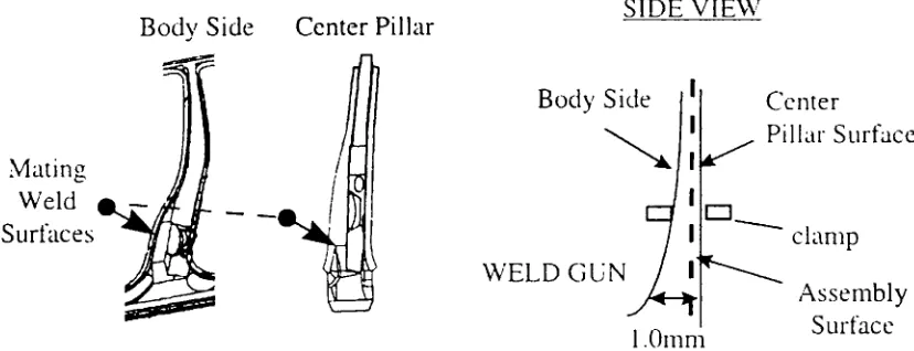
[image:6.559.80.494.67.226.2]To illustrate
why
the functional buildapproach
works,
Figure
4 considers themating
of the centerpillar
reinforce-ment and the
body
sidepanel.
The centerpillar
reinforce-ment is a thicker, structural component and thus will have
greater
influence on the finalassembly.
Eventhough
thisbody
sidepanel
dimension is I mm outboard from thedesign
target, the centerpillar
is at nominal, thus the overallassem-bly
shifts toward nominal. This shift occurs because themat-ing
surfaces are inparallel.
Thus, the lessrigid body
sidepanel
conforms to therigid
inner structure[ 17].
Under a traditional build-to-nominal
approach,
amanu-facturer would
likely
rework thebody
sidepanel
because the outboardstamping
condition would cause this part to fail itsC~A
requirements.
In contrast, a functional builddeter-mine rework decisions based on the resultant
assembly
andnot
necessarily
onCpk
compliance.
In some cases, a resultantassembly might
still deviate from nominal, but it may beeas-ier and less
costly
toadjust
anassembly
processtooling
loca-tor to shift the
assembly
mean rather thanphysically
alter thebody-side stamping
die.When
making
achange
under a functional buildapproach,
manufacturers search for the least
costly
alternative withoutsacrificing end-product quality. Forexample,
if thequality
of thebody
isunacceptable
because an overall dimension ofseveral
parts
in asubassembly
is toolong, only
one part mayneed rework. In many cases, manufacturers choose the least
expensive
process for rework even if itproduces
a part withdimensions inside
specification
limits. Forexample,
adi-mension with a measurement of 0.5 mm out-of-tolerance could mate with a dimension at its nominal. In some cases,
altering
the dimension at nominal is lessexpensive
thanre-working
theout-of-specification
condition. Theobjective
isto
produce
anacceptable
finalassembly.
This solutionmight
differ for a manufacturer
using
a traditional,sequential
vali-dation
approach
where each part is evaluatedindependently
against
itsdesign print specifications.
Here, a manufacturermight change
the moreexpensive
process orpossibly
bothprocesses.
The functional build
approach
resembles robustengineer-ing
methods[ 18]
as manufacturers seek to redefinecompo-nent tolerances in which the
assembly
is insensitive tocom-ponent
variations.However,
twoimportant
distinctions should be made between functional build and most robustde-sign
methodologies.
The first distinction relates to toleranceexpansion
versus nominaladjustments.
Functional buildtyp-ically
involvesredefining
nominalspecifications
whilemaintaining
design
tolerance widths or allowablecompo-nent variations. In other
words,
functional buildsuggests
thata mean deviation from the
original
nominalspecification
during manufacturing
validation may result in zero loss ifthis mean is maintained in
regular production.
However,once this new nominal is
established,
functional buildmanu-facturers
typically
try to maintain the allowable variationspecified
with theoriginal
tolerance widths. In contrast,ro-bust
design
methodsusually
involveexpanding
component tolerance widthsprovided
the additionalcomponent
varia-tion does notadversely
affect theassembly.
A seconddistinc-tion with funcdistinc-tional build is that it is
rarely
based onplanned
experimentation.
Theprincipal
reasons that manufacturersutilize functional build relate to their
inability
toproduce
component dimensions at nominal and the
complex
correla-tion structure that exists formultiple
dimensions on the samecomponent.
These two factorssignificantly
hinder theability
to construct
meaningful experiments
thatindependently
as-sess theimpact
of differentcomponent
dimensions on are-sultant
assembly.
Ifexperimentation
isused,
ittypically
in-volvesadjusting assembly
parameters
to determine ifcomponent
rework may be avoided.7. Functional Build Case Studies
To
highlight
thepotential
effects ofapplying
flexiblecom-ponent criteria in the back-end of
product development,
weexamine three automotive
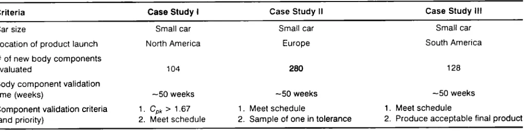
body
launches. Table I summa-rizeskey
differences and similarities between launches.Table 2 compares the validation
performance
for each launch. In the first casestudy,
the manufacturer has strictCm
requirements
for allpart
dimensions. Assuch,
they
submitmore components late to
assembly
validation and notsur-prisingly
havedifficulty getting
partsapproved
forproduc-tion. One reason is that many build
problems
are not identi-fied untilassembly
validation.By
over-focusing
onmeeting
component
requirements,
this manufacturer limits theirca-pability
forearly
detection of thoseassembly
build concernsthat affect external customer
perceptions.
Case
Study
II also involved strict criteria forcomponent
dimensions,
but this manufacturerplaces
agreater
emphasis
on schedule conformance.They
begin
assembly
validation on schedule evenif component
dimensions are not incompli-ance.
Unfortunately,
they
useassembly
validationprimarily
to
identify
new buildproblems
and notnecessarily
toevalu-ate if
non-conforming
component features affect the build.As a result,
they
continue to reworkcomponents
trying
tomeet
original
specification
requirements
in addition toincor-porating engineering changes
to correctassembly
build con-cerns. In efforts to minimize the risk ofassembly
problems,
this manufacturer also
assigns tighter
tolerances oncompo-nents than the other manufacturers. Their efforts to achieve
tighter
tolerances, however,
result inhigher
component
[image:7.559.15.525.624.753.2]Table 2.
Comparison
ofcomponent
criteria andapproval
rates.*Note: the tolerances used to approve these components are Ughter than at the other case studies.
work costs and
longer
lead-times toget components
ap-proved.
The most
interesting
results occur in CaseStudy
III. This manufacturer has the loosest componentrequirements
butactually
approves components at a faster rate.They
have nearsimultaneous
approval
of components
and assembles, ratherthan the traditional
sequential approach.
Theirgoal
is to firstproduce
parts with stable variation and mean dimensionswithin a
design
window(80%
of part dimensions withinspecitication).
They
then use downstreammanufacturing
validation processes to determine which component dimcn-sions
require
rework.The
ke:y
for this manufacturer is the closerelationship
be-tween evaluators of components and assemblies. Theiras-sembly
validation teamrecognize
thatmeeting
all compo-nentrequirements
is notnecessarily
critical to the build, andas a result, more
willingly
acceptsnon-conforming
compo-nent dimensions. Their functional build strategy does not
presume that all component deviations are
acceptable. They
rework some component mean deviations, but
they
alsocom-pensate for component mean deviations
by adjusting
assem-bly tooling
or othermating
components.Regardless
of thesolution, functional build manufacturers are focused on the
final
product objectives
rather thantrying
tooptimize
indi-vidual componentperformance.
A hidden
key
to the success in CaseStudy
III is that onemanager is
responsible
for bothstamped
component andfi-nal
assembly quality.
From his total systemperspective,
he looks for the leastexpensive,
rationalquality
decision toev-ery
problem.
He is not concerned whether this involvesre-working
the component process ormaking
anadjustment
indownstream
assembly
processes.8. Conclusions
One result of
rising expectations
forimproved
time-to-market and finalproduct
launchquality
has been torequire
that
suppliers
meet strict component criteria withever-tighter manufacturing
tolerances.Unfortunately,
several manufacturerstighten
component tolerances withoutrigor-ously validating
that the revised tolerances willactually
im-prove assembles. Or.
they
do not consider the additionalsupplier
burdensresulting
fromassigning
unrealistically
tight
tolerances. These manufacturerssimply
want to &dquo;draw aline in the sand&dquo; and tell
suppliers
thattheircomponents
mustconform to all
requirements.
For components within a
complex assembly,
this researchsuggests that
loosening
component criteria mayactually
lead to a more efficientmanufacturing
validation process.Using
afunctional build
approach,
manufacturers nolonger
treatoriginal
tolerances as sacred. thusallowing
them to eliminateunnecessary rework.
By
viewing
validation as a total system,functional build manufacturers search for the best business decision to
produce
anacceptable
endproduct.
This decisionmight
entailreworking
anon-conforming
component, amat-ing
component, ormaking
anadjustment
to a downstreamas-sembly
process. As with the front-end ofproduct
develop-ment.
improving
manufacturing
validationultimately
depends
on betterintegration
of componentsuppliers
andfi-nal manufacturers toward
solving
thoseproblems
thattruly
affect the final customer.References
1. Clark, K.B. and T.
Fujimoto
1991. ProductDevelopment
Performance—Strategy, Organization,
andManagement
in the World AutoIndustry,
Boston, MA: Harvard Business School Press.2. Kamath, R.R. and J.K. Liker 1994. "A Second Look at
Japa-nese Product
Development,"
Harvard Business Review, Nov.-Dec.3. Karlsson. C., R. Nellore and K.
Soderquist
1998. "Black BoxEngineering: Redefining
the Role of ProductSpecifications,"
Journal of Product InnovationManagement.
Vol. 15, No. 6, pp.534-549.
4.
Bhattacharya.
S., V. Krishnan, and V.Mahajan
1998."Man-aging
New Product Definition inHighly Dynamic
Environ-ments,"Management
Science, Vol. 44, No. 11, November, pp. S50-S64.5. Moffat, L.K. 1998. "Tools and Teams:
Competing
Models ofIntegrated
ProductDevelopment
Performance," Journal ofEn-gineering Technology Management,
Vol. 15, pp. 55-85. 6. Haddad, C. 1996."Operationalizing
theConcept
of [image:8.559.35.552.77.204.2]IEEE Transactions on
Engineering Management.
Vol. 43. No.2,
May,
pp. 124-1 ~2.7. Ettlie, J.E. 1997.
&dquo;Integrated
Design
and New Product Success,&dquo; Journal ofOperations Management.
Vol. I5, pp. 33-55.8. Bohn. R.E. 1994.
&dquo;Measuring
andManaging
TcchnicalKnowledge,&dquo;
SloanManagement
Review, Fall 1994. 9. Jaikumar. R. and R.E. Bohn 1992. &dquo;ADynamic Approach
toOperations Management:
An Alternative to StaticOptimiza-tion,&dquo; International Joumal of Production Economics. Vol. 27,
pip.265-282.
10.
Upton,
D.M. and B. Kim 1998. &dquo;Alternative Methods ofLearning
and ProcessImprovement
inManufacturing,&dquo;
Jour-nal ofOperations Management.
Vol. 16, pp. 1-20.l 1. Ward, A.. J.K. Liker, J.J. Cristiano, and D.K. Sobek 1995. &dquo;The Second
Toyota
Paradox: HowDelaying
Decisions Can Make Better Cars Faster.&dquo; SloanManagement
Review, Vol. 36. Neo. 3.Spring,
pp. 43-61.12.
Liggett.
J.V. 1993. Dimensional VariationManagement
Hand-hook-A Guide forQuality, Design,
andManufacturing
Engi-neers.
Englewood
Cliffs. NJ: Prentice Hall.13.
Rodriguez.
R.N. 1992. &dquo;RecentDevelopments
in ProcessCa-pability
Indices,&dquo; Journal ofQuality Technology.
Vol. 24, No. 4. October, pp. 176-187.14. Pearn, W.L., S. Kotz and N.L. Johnson 199?. &dquo;Distributional and Inferential
Properties
of ProcessCapability
Indices,&dquo; Jour-nal ofQuality Technology,
Vol. 24, No. 4, October, pp. 216-231.I5. Hammett, P.C.. W.M. Hancock and J.S. Baron 1995.
&dquo;Pro-ducing
a World Class AutomotiveBody,&dquo; Engineered
inJa-pan-Japanese Technology Management
Practices. Editedby
J.K. Liker. J.C.Campbcll, and
J.E. Ettlie. N.Y.: OxfordUniver-sity
Press.16. Rosink, K.E.. T.
Reynolds
and M. M~ulton 1997. &dquo;The Process AssuranceBody
BuildSystems Tooling
Build[Plate Build. What Are the Benetits’?&dquo;Society
of AutomotiveEngineers
Pa-per No. 982404.17. Liu, S.C., S.J. Hu and T.C. Woo 1996. &dquo;Tolerance
Analysis
for Sheet Metal Assemblies,&dquo; ASME Journal of MechanicalDe-sign,
Vol. 118. March, pp. 62-67.18. Prasad. B. 1997. Concurrent
Engineering
Fundamen-tals-Volume II, Prentice Hall, pp. 98-1 10.Patrick C. Hammett
Pat
Hammett, Ph.D.,
is anAssis-tant Research Scientist in the
Manu-facturing
Systems
Group
of the Of-fice for theStudy
of AutomotiveTransportation.
He is involved inre-search
developing
andimplement-ing
world-classmanufacturing,
quality,
and managementpractices
in theproduction
anddevelopment
of the automotivebody for Chrysler,
Ford and General Motors. Aspart
of theBody Systems
Analysis
Task Force of the Auto-SteelPartnership,
ajoint partnership
con-sisting
of General Motors,Ford,
Chrysler,
and twelve North American steel manufacturers, Pat conducts research toas-sist the North American
stamping industry
inachicving
world classperformance
levels in automotivebody
develop-ment lcad time and dimensional
quality.
Pat is aprincipal
re-searcher and
supervisor
for several researchprojects
toopti-mize the automotive
body development
process at General MotorsCorporation.
He is alsoAdjunct-Assistant
Professor of Industrial andOperations Engineering, teaching
a course on TotalQuality Management
for theCollege
ofEngi-neering
for seniorengineers
andgraduate
students.Pat has a Ph.D. in Industrial and
Operations Engineering
from the
University
ofMichigan,
a Master of Science inEn-gineering
from theUniversity of Michigan,
and a Bachelor ofScience in
Engineering
from PurdueUniversity.
Shannon Wahl
Shannon Wahl is a student research assistant in the
Manu-facturing Systems Group
at the Office for theStudy
ofAuto-motive
Transporation
at theUniversity
ofMichigan.
As are-search assistant, shc has been involved in a
variety
ofprojects
to
optimize
the automotivebody-in-white development
pro-cess, as well as
projects
dedicated tounderstanding
andim-plemcnting
world-classmanufacturing practices.
Shannon received her Bachelor of Sciencedegree
from theUniversity
ofMichigan
in Industrial andOperations Engineering
and iscurrently pursuing
her Master of Sciencedegree
in the same area ofstudy.
Jay
S. BaronJay
is theManager
ofManufac-turing Systems
for the Office for theStudy
of AutomotiveTransporta-tion. He holds a Ph.D. and Master’s
Degree
in Industrial andOperations
Engineering
from theUniversity
ofMichigan,
and an MBA from RensselaerPolytechnic
Institute.Dr. Baron has been
researching
techniques
forachieving
process and dimensional control in sheet metalstamping
and autobody
as-sembly.
As part of his doctoral research, he hasdeveloped
new
analytical
methods andprocedures
tosupport
the di-mensionalanalysis
and control ofstamped
metalassem-blies.
Dr. Baron has also been
researching evolving technologies
in the autoindustry.
His interests are to conductmanufactur-ing analysis
andplanning
for the automotiveindustry,
con-centrating
onproductivity, product quality,
and systemeco-nomics,
and to assist in thedevelopment
andapplication
ofnew
manufacturing technologies
such ascomputer-assisted
develop-ment and
manufacturing
processcapability through
effectivedesign, development
andimplementation.
Prior to
becoming
a researcher at theUniversity
of Michi-gan, Dr. Baron worked forVolkswagen
of America inQual-ity
Assurance. He has also been a StaffEngineer
andProject
Manager
at the IndustrialTechnology
Institute in Ann Arbor, and RensselaerPolytechnic
Institute’s Center forManufac-turing Productivity
inTroy,
New York. While at theseorgani-zations,
hemanaged
consulting projects
for overtwenty
dif-ferentcompanies
inapplying
newmanufacturing
technology.
Severalprojects
were concerned withmanufac-turing
systems
and economicmodeling
to evaluate the