© 2018, IRJET | Impact Factor value: 6.171 | ISO 9001:2008 Certified Journal
| Page 1325
Multi-Crop Harvesting Machine
Mr. Ravindra Lahane1, Ankush Fuse2,Shantanu Dahake3,Saurabh Wakchaware4, Parth
Ditanwala5
1
Professor in Dept. of Mechanical Engineering , Dr.D.Y.Patil College of Engineering, Akurdi, Pune
2,3,4,5Student of Mechanical Engineering, Dr.D.Y.Patil College of Engineering, Akurdi, Pune
---***---Abstract
-India’s economy finds its roots in agriculture. More than 50% of workforce in India is dependent on agriculture. India being the largest producer of many crops like rice, pulses, spices and spice products it export these crops too. Now, as agriculture is this much important to India, farmers of India don’t get enough wages out of it and find it difficult to produce required quality and quantity of crops. This is due to high labor cost and highly expensive cultivating machines and as time is moving population of India increases so do the food requirements so taking into consideration all of the above mentioned problems this machine aims to be affordable and efficient. This machine is economical and helps farmer to achieve higher productivity.Key Words
:
Bevel Gears, Pulley and Belt drive, chassis1.INTRODUCTION
Time never stops and it seems growth of India’s population too so we need to increase the production of food but there are many barriers come across farmers during food production, which are needed to resolved. There are many machines which can increase the productivity and saves time but those are too costly farmers can’t afford them, some of them can, but most part of Indian farmers belongs to middle class and they can’t afford it. We require a machine which is efficient as well as economical. This machine aims to be the economical and efficient. Farmers can afford this machine and use it for small scale production, we are aiming for small scale production because most of the farmers who faces problems of labor deficiency and labor costs are producing the crops at small scale.
2. LITERATURE REVIEW
There are two types of harvesting, one of them is manual harvesting and other one is mechanized types of harvesting. The time required in manual harvesting is more than harvesting using machines, it takes approximately 15 to 16 labours to harvest one acre of land in 3 days. The labours being paid 500 to 550 Rupees. Per ton of harvest so total cost of harvesting of one acre of land comes around 30,000 to 35,000Rupees. In mechanization now by using large scale harvesting machine takes 6 to 7 hours for harvesting of 60 to 70 tons while labour cost is around 4,000
Rupees. Hence total cost occurs is approximately 20,000 to 25,000Rupees.
Dr. Sharad S.Chaudhari – His aim is fabricate a small machine to harvest a sugarcane which takes power from petrol engine and different mechanisms. Using this machine sugarcane cut faster rate compare to manual harvesting.
Joby Bastian - The mechanical properties of the plant material significantly influence the performance of the different unit operation in combine harvester. While checkiong the mechanical properties it is found that the Young’s modulus of the sugarcane stalks as 86MPa, The specific cutting resistance varies between 1764.56 and 957.48kN/m^2, penetration resistance ranging from 29.74kN/m^2 to 56.33kN/m^2 and the crushing force varied from 0.75kN to 1.53kN.this study helped us very much while deciding the forces required to cut the cane in one knocking stroke.
R. R. Price - A fibre optic yield monitoring system was developed for a sugarcane chopper harvester that utilized a duty cycle type approach with three fibre optic sensors mounted in the elevator floor to estimate sugarcane yield. The average observed prediction error on 0.5 to 1.6 Mg estimates was 7.5%; though, the magnitude of the error decreased as the harvested area (tonnage) increased, with an estimated error of 0.03% for 57.8 Mg loads.
3. METHODOLOGY
© 2018, IRJET | Impact Factor value: 6.171 | ISO 9001:2008 Certified Journal
| Page 1326
cutting force so by using that force we can cut other crops too.
4. CALCULATIONS
4.1. Design of Shaft:
Design Torque, N-m Td = (60 P*Kt)/2πN And we also have Td = π/16*d^3*τmax
Where, d = diameter of shaft Maximum shear stress, τmax =< 0.18 Sut or < 0.3 Syt Selecting material EN8
Sut = ultimate stress = 750 Mpa Syt = yield strength = 465 Mpa From this we get
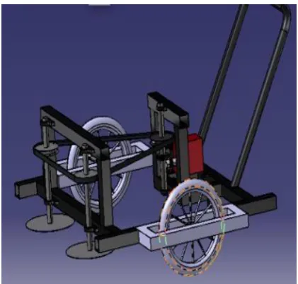
[image:2.595.56.267.280.481.2]τmax = 0.18 Sut =139.5 Mpa
Fig 1– 3D CAD Model Selecting lower value,
τmax=135 Mpa
If we used key then we can reduced the stress, τmax=0 .75*135 = 101.25 Mpa
Design Torque, N-m Td = (60 P*Kl)/2πN And we also have Td = π/16*d^3*τmax
Where, d = diameter of shaft
Td = 2.73632119 N-m = π/16*d^3*τmax
Therefore we get d =5.18mm.Increase the diameter by 50% to sustaining the various load
d = d+d*0.5 d= 7.77 mm
Selecting standard value ds = 20 mm
4.2. Design of bevel gears
:Design power, Pd = Pr*kl For steady and continuous work Kl = 1.25
Rated power, Pr= 1 kW Therefore, Pd = 1.25 kW
NP = 3500 rpm
Assume velocity ratio = 1
Minimum no, of teeth, Tp= 18 Therefore, Tg = Tp
Tg=18 teeth Ng = 3500 rpm Pitch angles, γ For acute angles gears
For pinion,
θ = angle between axes of shafts = 90 degree γ =45 degree α=20 degree
Torque produced,
Mt= ((60* 10^6*1.25)/2π*3500) DP=m*Zp DP=m*18,
Now, tooth load, Ft Ft= (2*Mt)/Dp,
Ft= (2*2763.211)/18*m, Ft = 307.023/m N
For generated tooth, Cv = velocity factor Cv = 5.6/ (5.6+√v) Effective Load,
Peff= (Cs*pt)/Cv = 322.5/m
Assume,
b/L=1/3 and b=10*m tan γ=Zg/Zp’=18/18 Therefore,
γ =45
Zp’= Zp/cos γ Zp’= 18/cos (45) Zp’=25.455 Lewis foam factor=0.308
Beam strength, Fb
Fb = Sb*Y*m*b*(1 – B/L) Where, Sb= bending stress
Sb=Sut/3=551/3 Sb =183.66 Mpa
FB = m*10*m*183.66*0.308[1-(1/3)], = 377.128*m^2
Comparing FB and FT,
Feff= 322.5/m * F.O.S = 377.128*m^2 322.5/m * 2 = 377.128*m^2m=1.061 Standard module, m=3 mm Therefore, Diameter of gear is Dg = 54 mm Diameter of pinion is Dp = 54 mm Pitch line Velocity,
Vp = πDN/ (60*1000), m/s = π*54*3500(60*1000) m/s Vp = 9.89 m/s
Fb= 377.128*m^2
Fb = 3394.152 N Ft = 307.023/m N Ft =102.341 N
L = 0.5√ (〖Dg〗^2+〖Dp〗^2) L=38.183 mm B=10*3
B =30 mm Here,
FB actual >FT, Hence design is safe and feasible. Dynamic load
Fd = FT+ (21Vp (Ceb+FT))/ (21Vp+√ ((Ceb+FT))) Where,
Error = 0.012 mm
=102.341+ (21*9.89(11400*0.012*30+102.341))/ (21*9.89+√ ((11400*0.012*30+102.341)))
© 2018, IRJET | Impact Factor value: 6.171 | ISO 9001:2008 Certified Journal
| Page 1327
For finding actual factor of safety. Beam strength,
Fb = m*10*m*233.33*0.308[1-(1/3)], = 377.128*m^2
Fb = 3394.1`52 F.O.S = Fb/Pe
= 3394.15/3307.72 F.O.S =2.66
Now for limiting wear strength, Fw Fw = (K.b.Dp.Q) Where,
Q = size factor = 2Tg/[Tg+Tp*tan γ] =1
K=0.75* [BHN/100] ^2 Now,
Fw = Pe * F.O.S Where, Pe = Cs * Ft+ Fd
= 3307.72 Therefore,
Fw = 3307.72 *1.026 Mpa
Fw = [0.75*30 *1 *18/cos 45] * [BHN/100] ^2
From above equations, BHN=140.53
The material chosen have BHN > 140.53, Hence our design is safe and feasible.
4.3. Design of v-belt:
Rated power of Engine, Pr = 4 kW
Speed of Engine, N1 = 5500 rpm Design Power, PD = PR*Kl
Loading factor Kl = 1.1PD = 4.4 kW
Now select designation from design power,
Designation is B, Therefore, Diameter of smaller pulley, d= 100 mm
Diameter of larger pulley D=1.8*d
D= 180mm
w = 13 mm, t = 8mm, Center distance, C = D+ 1.5 * d
C= 180+ 1.5 *100C=330 mm
Length of belt
180+100)/2 + 2* 330 +(180- 100)^2]/4* 330L
=1104 mm Therefore,
Preferred length from table 13.4 B section, L=1100 mm For Corrected center distance, L=
1100 *(100+180)/2 + 2* C+ (180-100) ^2]/4* C
C=327.64 mm Therefore,
Correction factor for Pitch length,
From table 13.34 design data book V.B.Bhandari for B section, Fc=0.85 Correction factor for arc of length,
From table 13.17,
α = 180 – 2*sin^-1[(D-d)/2] =165.98 =166 degree From table 13.35, Fd =0.97 Power Rating (Pr) –
From table 13.29, at 2750 rpm, 13mm thick
Pr = 2.52+0.34=2.86 kW Number of belts, P*Fa/Pr*Fc*Fd =4*1.1/2.86*0.87*0.97
=1.82 = 2 Appx.
4.4. Design of shafts:
A) Shaft carrying bevel gear and pulley
For Force on pulley, F1 Power = 2*π*N*T/60 1*10^3 =2*π*3500*T/60 T=2720 Nmm
Where r=pitch circle radius =24 mm F1=Total tension force on pulley 2720=F*0.24
Therefore, F1=113.682 N
For Force on bevel gear, F2
Ft= 102.341 N Fr= 26.339 N Fa = 26.339 N
For vertical plane following figure shows bending moment diagram
Fig 2 – Bending Moment Diagram
R1+R2 = 216.021 N R1*300 – 103.34*146 = 0 R1 = 124.75 N
R2 = 91.668 N
Moments,
Moment about c, Mc=
103.5*216.021=22358.173 Nmm About D, Md
= 216.021*154 – 113.68 *50.5 =27526.394 Nmm
© 2018, IRJET | Impact Factor value: 6.171 | ISO 9001:2008 Certified Journal
| Page 1328
Fig 3 – Bending Moment Diagram
R1+R2 = 26.339 N R1*300 – 26.339*146 = 0 R1 = 12.818 N& R2 = 13.52 N Moments, Moment about c, Mc
= 0 N mm About D, Md
= 12.818*154 =1973.973 N mm Therefore,
Resultant bending moment at D, Md = √ [(27526.39) ^2 + (1973.97) ^2] = 27597.077 N mm
Equivalent Torque by using ASME code, Teq=√ [(Kb*Mb) ^2 + (kt*T) ^2] Where, For material EN8
Kb = 1.1 & Kt = 1.5
Teq= √ [(1.1*27597.07) ^2 + (1.5*2763.2) ^2]
Teq = 30638.429 Nmm By using Torsional equation, 30638.429 = (π*D^3 * τ)/16
= (π*D^3 * 135)/16 Therefore,
D = 10.494 mm Selecting standard diameter, D= 20mm
B) Shaft carrying pulley and cutter
For Force on pulley, F1
Power = 2*π*N*T/60 1*10^3=2* π*3500*T/60 Therefore,
T=2720 N mm Torque, T=F1 *r
F1=total tention force on pulley, 29997=F * 24
Therefore, F1=113.628 N
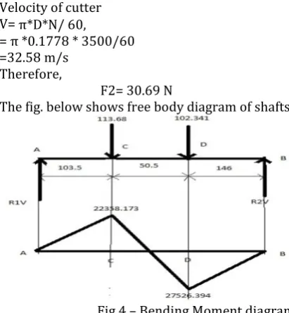
For Force on cutter,F2 Velocity of cutter V= π*D*N/ 60,
= π *0.1778 * 3500/60 =32.58 m/s
Therefore,
F2= 30.69 N
The fig. below shows free body diagram of shafts,
Fig 4 – Bending Moment diagram
For calculating reaction forces, R1+R2=113.682+ 30.69 R1*290-113.682*180+30.69*150 = 0
Solving above two equations, we get R1=54.687N
R2=89.685N BM at A= 0,
BM at B = -30.69*150=-4603.5 N mm BM at C =-54.687*110 =6014.8 N mm
Equivalent Torque by using ASME code, Teq=√ [(Kb*Mb) ^2 + (kt*T) ^2] Where,
Kb = shock and fatigue bending factor Kt = shock and fatigue torsion factor For material EN8
Kb = 1.1 Kt = 1.5
Teq= √ [(1.1*6014.8) ^2 + (1.5*2720) ^2] Teq = 7773.1307 N mm
By using Torsional equation, 93798.796 = (π*D^3 * τ)/16
= (π*D^3 * 135)/16 Hence
D=6.663mm
Selecting standard diameter=20mm.
4.5. Selection of Bearings:
Diameter of Shaft, d =20 mm, Speed of shaft, n = 1530 rpm,
Radial component of force, fr=106.75 N Axial component of force
Fa = 0 N
Bearing Life = L10ha = 12000 hours Therefore,
[image:4.595.82.265.129.283.2]© 2018, IRJET | Impact Factor value: 6.171 | ISO 9001:2008 Certified Journal
| Page 1329
Dynamic Load Capacity, C Equivalent dynamic loading, P P = Fr,
Because axial component is zero. C = P*(L10) ^1/3 = *(1101) ^1/3
= 1102.23 N
From table 15.5 From V. B. Bhandari, Following bearings are available for diameter is equal to 20 mm,
No. 61804 (C = 2700) No. 16404 (C = 7020) No. 6004 (C = 9360)
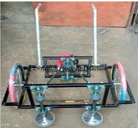
[image:5.595.37.277.227.449.2]Therefore, Bearing no. 61804 is selected for above application
Fig 5 – Actual Fabricated Machine
5. CONCLUSION
This machine is designed with considering all the parameters of actual agricultural field so it is practically applicable for small scale production. The cost of the machine is economical so Indian farmers can afford it. They can use this machine for higher productivity and it also saves time. The problems like labour deficiency and high labour cost can be partially eliminated by using this machine.
6. REFERENCES
[1] T. Moontree, S. Rittidech and B. Bubphachot “Development of the sugarcane harvester using a small engine in Northeast Thailand” International Journal of Physical Sciences Vol. 7(44), pp. 5910-5917, 23 November, 2012
[2] R. N. S. Yadav, D. Chaudhuri, M. P. Sharma P. R. Singh, S. D. Kamthe, A Tajuddin “Evaluation, refinement and development of tractor operated sugarcane cutter planters” Sugar Tech, Volume 6, pp June 2004
[3] Suleiman Samaila, Hamid Mohammed Al-Sharief and Salihu Ahmed Abdulkadir “Development of a Tool to Determine the Energy Required to Cut and Top Sugarcane.” (Jul. 2012)
[4] Rohit J.Masute, S. S. Chaudhari , S. S. Khedkar, B. D. Deshmukh “Review paper on different aspects of Sugarcane harvesting methods for Optimum performance” International Journal of Research in Engineering and Applied Sciences IJREAS, Vol. 02, Issue 01, Jan 2014
[5] H. Taghijarah, H. Ahmadi, M.Ghahderijani, M. Tavakoli “Shearing characteristics of sugar cane (Saccharum officinarum L.) Stalks as a function of the rate of the applied force” AJCS 5(6):630-634(2011) ISSN: 1835-2707