“Traffic analyzer” Congestion Control Algorithm for
Datacenters
Mehdi Mohtashamzadeh
Department of Computer
Engineering
Soosangerd Branch, Islamic
Azad University
Soosangerd, IRAN
Mehdi Harizi
Department of Computer
Engineering
Soosangerd Branch, Islamic
Azad University
Soosangerd, IRAN
Aref Saiahi
Department of Computer
Engineering
Soosangerd Branch, Islamic
Azad University
Soosangerd, IRAN
ABSTRACT
Ever increasing amount of data in networks may lead to congested networks, routers with full queues, increase of loss rate, and end-to-end latency. As a result effective throughput in networks would be plummeted. To deal with such challenges routers have to route packets faster and more precise. This concern seems to be more important in the backbones and regions near datacenters (which are crucial segments of nowadays networks), since they must tolerate with tremendous amount of traffic. Researchers have proposed different routing lookup algorithms, but since most of those need some memory accesses, routing process speed is limited to memory speed. In this paper, concentration is on flooding traffic beyond datacenters. Beyond doubt decreasing traffic volume in the regions close to datacenters, which absorb large proportion of traffic, can effectively improve congestion status and overall throughput of network. This research proposes that network can be segmented into regions according to distance of nodes from datacenters and backbones and different policies and routing algorithms would function in each segment. This method can effectively deduct the load on hardware and software in networks. Results show notable improvements in Round Trip Time (RTT), latency, and queue length parameters in routers.
General Terms
Congestion control, Datacenter performance.
Keywords
Datacenter; Congestion control; Cooperative caching
1.
INTRODUCTION
Datacenters have their roots in the huge computer rooms of the early ages of the computing industry. The boom of datacenters came during the dot-com bubble. Companies needed fast Internet connectivity and nonstop operation to deploy systems and establish a presence on the Internet. New technologies and practices were designed to handle the scale and the operational requirements of such large-scale operations. These practices eventually migrated toward the private datacenters, and were adopted largely because of their practical results. On the other hand high speed links (10Gbps and faster) are widely used in all networks. Furthermore, resent researches on Dense Wave Division Multiplexing (DWDM) show that hundreds of channels can be packed into a single fiber which means transmission speed of Terabits per second. Bad news is that hardware and software technology in routers has not experienced such significant changes during recent years. Researchers have proposed many solutions to compensate this backwarded state. A case in point is IP address caching [1]. Routers need to analyze each packet header to find out the destination address, then router should
spend some time on searching routing table which means few memory accesses and executing appropriate software. Since this procedure should be applied to each packet, it becomes a bottleneck in routing. To improve this situation, details of recent routings would be saved in a high speed memory named IP cache. This function is based on the fact of locality of destination IP addresses [2], [1]. Although locality of memory accesses in a stand-alone computer is considerable, destination IP addresses do not possess high degree of locality and as a result IP caching would not make the routing procedure faster. To overcome this challenge “routing prefix caching” [3] has been proposed. Howeversimulations show that locality of IP addresses in regions close to a datacenter is high enough so that using effective caching methods may significantly improve routing speed.
Cooperative caching [4], [5] is another approach to increase the routing procedure speed. This method is used due to memory limitations and delay in destination calculations which nodes in a network are faced with, especially in wireless networks. A central node can be considered to cache destinations‟ addresses or to compute the next hop address in case of a cache miss. Facing a packet which its destination IP address is not cached, router can send a request to the central node. This node returns routing details from its cache (cache hit) or compute it by running routing algorithm (cache miss). Finally the router uses the information and puts them in its cache for further accesses in future due to locality.
Current research considers network in segments, each segment has its own policies for accepting packets from other segments, caching and routing due to its distance from datacenter. We took advantage of cooperative caching with some modifications including decentralizing cooperative caches.
2.
PROPOSED METHOD (TRAFFIC
ANALYZER ALGORITHM)
of this type, it should decide to acknowledge only one of them according to its distance from center of regions. It is worth mentioning if two routers which their distance is less than 100 hops are selected to be leaders, one of them should turn over its leadership role. Routers would be informed of such conflict after broadcasting mentioned packets with specified TTL. Afterwards a comprehensive map of each region can be set in leaders‟ caches. From now on, leaders can function as cooperative caches and routing table computers in their corresponding regions. To decentralize this role, a leader may select few routers at other places of its region (north, south, east, and west) to do such duties in each sub-region. In simulations, each leader router was set to send out four “sub-region leader selection” packets from its ports.
Since place of leaders is known in a static network (even before running the network), they would be facilitated with large and advanced caches. However this research is based on dynamic networks in which nodes can be attached or detached at any time. In dynamic mode, a new node can get the information of the region it is located in by contacting its nearest neighbor.
In the final phase, leader sends messages to boundary nodes to remind their critical duty. Entering a new region, data packets must convince the boundary nodes to give them entrance permission. A boundary node in a region near to datacenter can analyze the destination address of the packet and understand whether the packet is going to reach the datacenter (by the use of IP prefixes [3]) or not. Based on this analysis it decides to give entrance permission or to reroute the packet to another region far from datacenter. If it is supposed to route packet into the region, each router should search its cache for routing information. In case of a cache miss, router should look up its memory. If memory does not contain routing details then the router can send a “cooperative cache use” request to the sub-leader of the region. However, router should put this packet into a buffer until receiving a response from sub-leader or leader and process next packet from queue. The algorithms used in boundary nodes and leader are presented in Table1 and Table2.
Table1. Applied algorithm for boundary nodes
Pick a packet from router queue;
If (a normal packet for routing is picked) then Pick a packet from router queue;
PART A
If (a normal packet for routing is picked) then Extract “IP Prefix”;
If (“IP Prefix” is not related to Datacenter close to this region) then
Reroute packet to a region far from current Datacenter; Else If (Leader has declared congestion and asked for
temporary rerouting) then
Set “rerouted packet” flag in the packet to 1;
Set “source region number” field in the packet with the number of current region;
Reroute packet to an adjacent region; Else
Search router cache for routing info; If (cache hit) then
Route the packet using obtained info from cache; Else if (cache miss) then
Search routing table in memory of router for routing info;
If (memory hit) then
[image:2.595.306.544.67.527.2]Route the packet using obtained info from routing
table;
Call cache replacement procedure if cache is full; Insert routing info into the cache;
Else if (memory miss) then
Send “cooperative cache use” request to sub-Region-leader;
Buffer packet till receiving response from leader or sub-leader;
Pick another packet router queue and restart the algorithm;
End if; End if; End if;
PART B
Else if (a “congestion status request” is picked) Then If (congestion controller detects congestion) then Set “congestion status Response” flag to „1‟; Else
Set “congestion status Response” flag to „0‟; End if;
Send “congestion status Response” packet to leader;
PART C Else if (a “Reroute request” is picked) then
Set “Rerouted packet” flag of packets in queue to 1; Set “Source Region Number” field of packets in queue with number of current region;
Reroute packets in queue to adjacent regions;
PART D
Else If (a “cooperative cache Response” is picked) Then Pick corresponding packet from buffer;
Extract routing details in “cooperative cache Response” message;
Route packet;
Call cache replacement procedure if cache is full; Insert routing info into the cache;
End if;
Restart the algorithm;
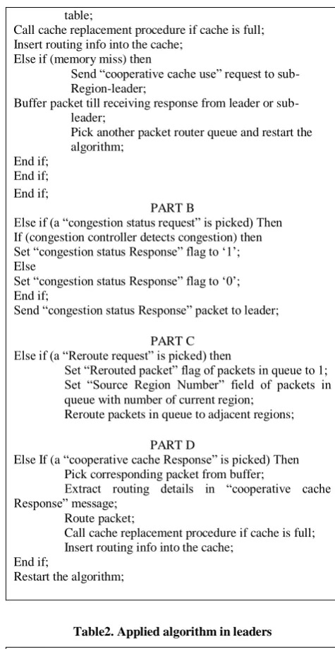
Table2. Applied algorithm in leaders
Pick a packet from router queue;
If (“cooperative cache use” request packet is picked) then Search router cache for routing info;
If (cache hit) then
Return routing detail to requester; Else if (cache miss) then
Search routing table in memory for routing info; If (memory hit) then
Put routing detail in a “cooperative cache response” packet;
Return “cooperative cache response” packet to requester; Call cache replacement procedure if cache is full; Insert routing detail into the cache;
Else if (memory miss) then
Run lookup algorithm to find routing info;
Put routing detail in a “cooperative cache response” packet;
Return “cooperative cache response” packet to requester;
Call cache replacement procedure if cache is full; Insert routing detail into the cache;
End if; End if;
Else if (a normal packet for routing is picked) then
Obtain Routing info from cache, memory, or by running lookup algorithm;
Route the packet using obtained info; End if;
Repeat the algorithm;
Experiencing high level of congestion by a region, central leader would temporarily ask the boundary nodes (nodes in specific parts or all of the nodes) to reroute hefty part of traffic to adjacent regions. In this case packets should be marked in a defined way before rerouting so that the boundary nodes of the adjacent regions permit them to enter their regions. We considered a flag (“rerouted packet”) and a field (“source region number”) in each packet to achieve this goal. To deploy this mechanism, each router should send its information about network congestion to the leader. Analyzing received information from routers, leader can understand the congestion level in different parts of its region and make regional decisions for various parts of the region. This process could be done using algorithm in Table3 (for leader) and “PART B” and “PART C” of the algorithm in Table1 (for boundary nodes).
Table3. The algorithm used by leaders for controlling congestion level.
„**This algorithm has been executed periodically during simulations**‟
Broadcast “Congestion status request” packet to all nodes; Wait until receiving “congestion status response” packets from all nodes;
If (some responses state existence of congestion) then Send “Reroute Request” packet to boundary nodes in appropriate sub-region;
End if;
3.
SIMULATION AND RESULTS
Simulations have been done using NS simulator [6]. Links are of 10Gbps types. Each router has 1MB tail-drop buffer. To show effect of Traffic Analyzer algorithm on network parameters we focused on three adjacent regions (“zone A”,
“zone B”, and “zone C”). Nodes which are located in “zone A” generate traffic towards “zone B”. In the following, two scenarios are described.
Unquestionably the proposed mechanism in this research bothers from processor overhead to raise robustness and availability of the network. However it is not the concern, since delay based congestion control is much preferred in a datacenter rather than a loss based [7]. This work takes advantage of deploying SCTP congestion control mechanism [8] (a delay based algorithm) instead of the aged TCP which is a loss based approach.
3.1
Simulation results with long-lived flows
To keep the network busy during simulations, several flows were injected in various times. 1st flow starts at 0 ms, two flows at 10 ms, 8 flows commence at 20 ms, 4 flows at 30 ms, 16 flows at 40 ms, and 8 flows at 50 ms. At 60 ms all the flows apart from the first and the fifth groups are terminated.Scenario 1
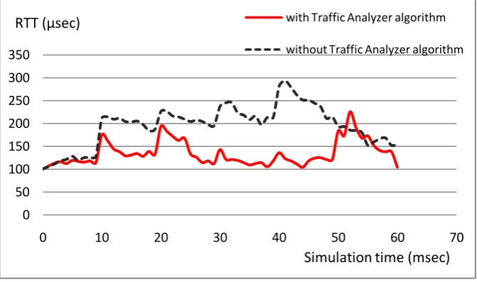
Hefty portion of the flows (4th and 5th groups of flows at 30 ms and 40 ms respectively) which are going from “zone A” toward “zone B” are not actually related to “zone B” according to IP prefixes of packets in the mentioned flows. Hence Traffic Analyzer algorithm in boundary nodes of the “zone B” reroute packets to adjacent region (“zone C”), whereas the network without proposed algorithm (and without region considerations) deal with these flows like others and conduct them inside the area which we named it “zone B” in simulations. As a result occurrence of congestion would be probable. Figure 1 shows the RTT results with and without Traffic Analyzer algorithm.
It is evident that shortly after injecting each bracket of flows RTT shows an upward trend. However, proper performance of the Traffic Analyzer algorithm can be deduced at 30 ms and 40 ms in Figure 1 in which variation of the RTT parameter is dispensable. This is due to packet reroute decisions which are taken by boundary nodes of the “zone B” in accordance with their capability to differentiate valid and invalid packets on their entrance to the “zone B”. On the other hand, existence of peaks at 30 ms and 40 ms are remarkable in the network without Traffic Analyzer algorithm. Almost after 55 ms most flows are terminated. This issue is reflected as a decremental
[image:3.595.130.466.547.745.2]trend after 55 ms.
Fig 1: RTT results in “zone B” with and without Traffic analyzer algorithm (Scenario 1).
0
50
100
150
200
250
300
350
0
10
20
30
40
50
60
70
with Traffic Analyzer algorithm
without Traffic Analyzer algorithm
RTT (µsec)
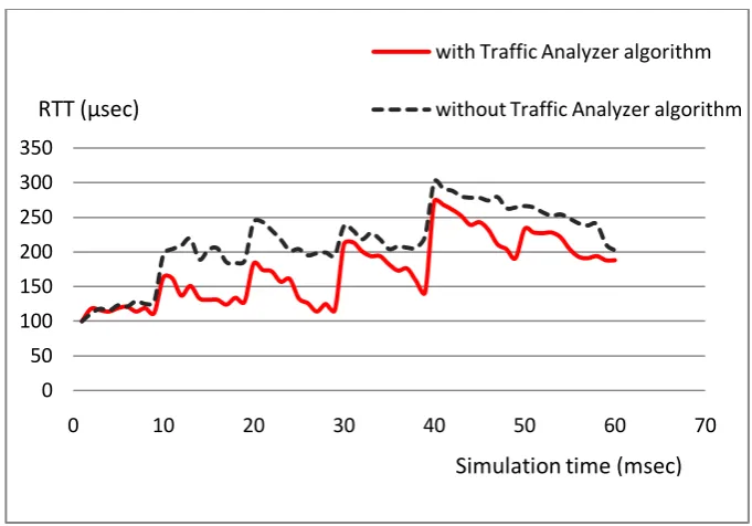
Fig 2: RTT results in “zone B” with and without Traffic analyzer algorithm (Scenario 2).
Overall, Traffic Analyzer algorithm has limited the RTT changes, while RTT largely revolves around 120 us during simulations.
Scenario 2
All traffic flows are related to “zone B”. in this case “zone B” may experience congestion. Hence region leader can send “Reroute request” to boundary nodes to reduce congestion level. Such requests have been sent from “zone B” leader to the boundary cells at (30+δ) ms and (50+δ) ms during simulations (Figure 2). One can extract from Figure 2 that conciselyafter 30 ms, and 50 ms RTT has significantly plummeted due to preventing packets to enter “zone B”. However, congestion level in the network without proposed algorithm is higher and steadier and it takes SCTP algorithm some times to effectively improve this situation.
In comparison with the first scenario, RTT values are considerably
larger
in this case because all the flows are related to the “Zone B”.Similar rises and falls in Figure 2 for two cases (with and without Traffic Analyzer algorithm) are results of traverse of nearly same route paths by overwhelming proportion of packets in both cases. However, notable RTT improvements by Traffic Analyzer algorithm are due to special properties of Traffic Analyzer algorithm, namely cooperative caching and reroute actions by boundary nodes. As mentioned above, reroute requests were reported by simulator at (30+δ) ms and (50+δ) ms. Furthermore, several cooperative cache requests have been detected by simulator (e.g. at 9, 13, 22, 28, 36, and 41 milliseconds), while the applied SCTP algorithm in our implementation suffered from lack of cooperative caching. Unquestionably, rerouting packets from “zone B” to “zone C” may put some stress on the “zone C”. This fact can be seen in Figure 3. “zone C” receives its own related traffic at 0 ms, 25 ms, and 45 ms. In addition, rerouted packets from “zone B” are captured after (30+δ) ms and (50+δ) ms. At these times RTT is increased. This increase is relatively high at (30+δ) ms and simulator reported transfer of “Reroute request” packets from the leader of “zone C” to its boundary cells. Improvement of RTT parameter as the consequence of reroute
[image:4.595.317.543.365.530.2]action by boundary nodes of “zone C” is evident shortly after 30 ms.
Fig 3: RTT results in “zone C” with Traffic Analyzer algorithm.
4.
CONCLUSIONS
With an increase in the uptake of cloud computing, business and government organizations are scrutinizing datacenters to a higher degree in areas such as availability, performance, security, environmental impact, and adherence to standards. Since datacenters absorb tremendous amount of data traffic, existence of appropriate congestion avoidance algorithms seems to be a vital aspect.
In this research, network is considered in regions. Each region has its own leader and policies. Traffic analyzer algorithm running on boundary nodes of a region checks all packets on their arrival. Boundary nodes are capable to determine whether the packet is supposed to reach the datacenter (permitted) in accordance with its IP prefix or not. Furthermore, the leader which is located at the center of region, can track congestion status in its corresponding region and make proper decisions to decrease congestion level. Although proposed algorithm may lead to force overheads in
0
50
100
150
200
250
300
350
0
10
20
30
40
50
60
70
with Traffic Analyzer algorithm
without Traffic Analyzer algorithm
Simulation time (msec)
RTT (µsec)
0
50
100
150
200
0
20
40
60
80
Effect of Traffic Analyzer
algorithm on RTT in "zone C"
RTT (µsec)
communications and processing times, improvements in RTT and loss rate are noticeable.
5.
REFERENCES
[1] Talbot, B., Sherwood, T., and Lin, B. 1999. IP caching for terabit speed routers. In proceedings of the Globecom conference.
[2] Chiueh, T.C. and Pradhan, P. 1999. Cache Memory Design for Network Processors. In proceedings of the HPCA Symposium on High-Performance Computer Architecture.
[3] Liu, H. 2001. Routing Prefix Caching in Network Processor Design. In proceedings of the ICCCN conference on Computer Communications and Networks.
[4] Saihan, F. and Issarny, V. 2003. Cooperative Caching in Ad Hoc Networks. In proceedings of the MDM conference on Mobile Data Management.
[5] Johnson, D. and Maltz, D. 1996. Dynamic Source Routing in mobile ad-hoc networks. In Mobile Computing, Kluwer Academic Publishers.
[6] http://www.nsnam.org
[7] Martin, J., Nilsson, A., and Rhee, I. 2003. Delay based congestion avoidance in TCP. IEEE/ACM transactions on networking, vol 11, no 3, pp. 53-61.
[8] Brennan, R. and Curran, T. 2001. SCTP Congestion Control: Initial Simulation Studies. In proceedings of the Tele-traffic Congress (ITC 17) conference.
[9] Crovella, M. and Bestavors, A. 1996. Self-similarity in World Wide Web traffic: Evidence and possible causes. In proceedings of the ACM SIGMETRICS conference on measurement and modeling of computer systems.