A Comparative Performance Analysis of ARM based
Web Servers with Integrated and External Ethernet
Interfaces for Industrial Applications
Alen Rajan
PG Scholar Hindustan University
Chennai
Aby K. Thomas
Professor Hindustan University
Chennai
Rejin Mathew
PG Scholar Hindustan University
Chennai
ABSTRACT
Embedded technology is one of the emerging technologies in this most modern era. When networking technology is incorporated with the former, there is no doubt that the scope of embedded systems would be further more. Here we design an embedded web server by interfacing ENC28J60 with LPC2148 ARM controller. Also a second web server is made with LPC1768 controller with an integrated Ethernet Interface. Industrial appliances that require continuous monitoring are interfaced to both the web servers. Also sensors are interfaced to monitor various parameters in the Industrial area. Analysis of the performance of both the web servers is done. Both the systems are suitable for a wide variety of Industrial Applications.
General Terms
Ethernet, Internet, Networking, Protocol, Client, Server.
Keywords
Arm Controller, Embedded Web Server, Ethernet Controller, Network Communication, SPI Protocol, TCP/IP.
1.
INTRODUCTION
By the advancement of electronics, embedded technology has become a challenging field in this modern age. The single functioned, tightly constrained, reactive and real-time feature of these devices enhanced its importance in industrial, consumer and even in medical applications. Even to make our life easier, we depend on various embedded devices such as mobile phones etc. The arrival of Internet reduced the whole world communication boundary to that of a single village. When we are able to control embedded devices remotely via internet there is no doubt that the demand of these electronic stuffs will be more than before.
The implementation of embedded system networking is none other than the embedded web server [6]. A web server is a device that helps the client or the user to access the end devices or monitor various parameters using sensors remotely [2]. It is the central functional unit that hosts web pages when the client enters the IP address of the server in the web browser. It contains application to run the web pages and large memory space for the server functionality. Web pages are made using HTML and heart of the communication is TCP/IP protocol.
Network communication is implemented here by means of IEEE 802.3 standard that is Type1 Ethernet protocol. Ethernet technology is the most widely used LAN technology and we can bring this technology to device level by using the most modern technology of embedded systems. Ethernet Interface could be done by two ways [7]. One is the chip level
integration of the Ethernet with the processor. Here communication is done by means of an internal bus and inbuilt curing network protocol is available. The drawback of this system is the wastage of network resource. Second is by interfacing an external Ethernet controller to the processor. Here external bus is used. If parallel bus is used, then network traffic is slow. So in our system we use SPI protocol for the communication between processor and Ethernet controller, which is a serial communication protocol. Moreover, drop in communication in accordance with the length of the cable is the major drawback of serial communication [4].
Here we use ARM controller as the heart of the system. ARM has high speed of execution and powerful information processing capability [1]. The capacity of multi-parameter execution, multi-level monitoring and networking of ARM processor makes it suitable for a wide variety of networking applications. It can also overcome the operation pressure on data reduction and is capable real-time applications. The RISC architectural feature and large memory space made us to choose this processor as the heart of the web server. Conventional PC web servers require uninterrupted 230V a.c power supply round the clock and the implementation and maintenance of these bulky systems are very high [8]. When this is replaced by the low power embedded web server, the power consumption could be highly reduced since it requires only a low d.c power supply of 3.3V. When RTOS is incorporated into this system, more devices and sensors could be controlled and monitored at the same time. The multi tasking capability and fast response time along with capability of easy deployment increase the demand of this system than conventional PC web servers.
The system designed here is an example of embedded technology integrated with networking technology where communication and processing technology meets. Firmware development is done in embedded C language which is user friendly and also enhances the future development of the system. Front end of the EWS with external Ethernet Controller for user access is designed using Visual Basic and for EWS with integrated Ethernet is designed using HTML.
2.
SYSTEM HARDWARE DESIGN
The hardware design of the Embedded Web Server, features of the processors and the Ethernet controller is discussed in this section.
2.1
Embedded Web Server
units such as web server, industrial unit that needs to be monitored and finally the client unit for user access. In the first system, shown in Figure 1, the ARM controller used is LPC2148 and Ethernet Controller is ENC28J60 whose features are discussed later.
Figure 1: EWS with external Ethernet Controller
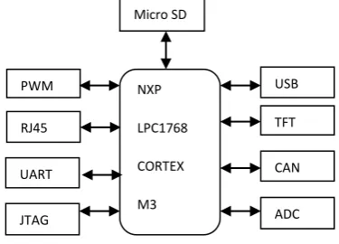
The EWS shown in Figure 2 is LPC1768 which has an integrated Ethernet Interface. Client can access monitor the device status by entering the corresponding IP address.
[image:2.595.62.241.150.289.2]Figure 2: EWS with Integrated Ethernet
2.2
LPC2148 Processor
[image:2.595.67.256.376.482.2]This is a 32-bit ARM7-TDMI-S microcontroller with 40kB of on-chip static RAM and 512 kB of on-chip flash memory. It has 128-bit wide interface/accelerator that enables 60MHz of operation. Also has In-System Programming using on-chip boot loader software, 400ms of full chip erase and 256 B of programming in 1ms. For interfacing of sensors, it has 10-bit ADC with 14 analog inputs and a conversion time as low as 2.44µs per channel. CPU operating voltage is 3V to 3.6V so that the proposed system requires only lower power consumption as the same mentioned before. The hardware schematic is shown in Figure 3. Architecture is based on RISC principles and this simplicity results in a high instruction throughput and real-time interrupt response form a small and cost effective processor core. It also have another architectural strategy such as 16-bit Thumb instruction along with 32-bit ARM instruction set which will enhance the code density in restricted memory conditions.
Figure 3: Hardware architecture of LPC2148
2.3
ENC28J60 Controller
This Ethernet Controller is designed to serve as an Ethernet network interface for any controller equipped with SPI. It has an internal DMA module for fast data throughput and hardware assisted IP checksum calculations. It incorporates a number of packet filtering schemes to limit the number of incoming packets and provides a data rate of 10Mb/s. the PHY module encodes and decodes data obtained from the twisted pair interface. The MAC module implements IEEE 802.3 compliant MAC logic. This is designed to operate at a crystal oscillator frequency of 25 MHz.
2.4
LPC1768 Processor
This is an ARM Cortex M3 based microcontroller for embedded applications with a high level of integration and low power consumption. CPU operating frequency is 100MHz with 3-stage pipeline and internal prefetch unit. It follows Harvard architecture. It has a 512kB of flash memory, 64kB of data memory, Ethernet MAC, USB data interface, 8 channel general purpose DMA controller, 4 UART‟s, 2 CAN channels, 2 SSP controllers, SPI interface, 3 I2C bus interfaces, 8 channel 12-bit ADC, 10-bit DAC, Ultra low power Real Time Clock, 6-output general purpose PWM, four general purpose timers and up to 70 general purpose I/O pins. Moreover this controller has System Programming and In-Application Programming functionality through in-chip boot loader software. RMII interface is provided to Ethernet MAC. Figure 4 shows the system structure of the microcontroller.
Figure 4: System structure of LPC1768
The ADC is of successive approximation type with a 12-bit conversion rate of 200kHz. Individual result registers is there for each ADC channel to avoid interrupt overhead. Moreover burst conversion mode is adopted for single or multilevel inputs. Devices are connected through fast general purpose parallel I/O pins. GPIO registers are accessed through AHB multilayer bus so that the fastest possible I/O timing can be achieved.
ARM Controller
Ethernet Controller
Sensors
Appliances Internet
Client
User 1
User 2
EWS Internet
Sensors & Appliances
NXP
LPC1768
CORTEX
M3
TFT
CAN
ADC JTAG
UART RJ45
USB Micro SD
PWM
LPC214
8
AD C
JTA
G
ENC28J60
TFT
[image:2.595.338.526.504.639.2]3.
COMMUNICATION MODULE
DESIGN
The MAC is connected to PHY by means of media independent interface (MII) and reduced media independent interface (RMII). The MAC layer is responsible for data packaging, closing, sending and receiving. As shown in Fig 3, MII is the interface between MAC layer and PHY layer. It‟s functions are providing clock synchronization for both reading and writing of data frame delimiter and also supports full duplex mode between MAC and PHY layer interfaces.
RX
TX
[image:3.595.314.545.98.206.2]
Figure 5: Internal structure of ENC28J60
[image:3.595.68.282.187.340.2]The Ethernet transformer connected between PHY interface and RJ45 connector as shown in Fig 4 is used to improve the signal anti-interference capability. This is a 1:1 transformer that supports 10Mbps Ethernet.
Figure 6: Network Communication Unit
3.1
SPI Protocol
The serial communication is performed by means of two pins that are SI and SO as shown in Figure 7. SCLK provides clock synchronization and CS is the chip select. This communication technique can be implemented between processor and peripherals that have SPI interface. Serial Peripheral Interface Bus is a synchronous serial date link standard where communication is performed in master/slave mode and master device initiates the data frame. This is a full duplex mode of point to point communication. The serial clock, SCLK generated by the master device is used by the slave also. The SS which is the Slave Select signal should in active low state for the slave to have communication with master. This is a four wire communication as shown in Figure 7. The SDO or Serial Data Output signal send by the master and after receiving the clock pulse, the slave device responds back with SDI or Serial Data Input signal.
Figure 7: SPI Interface
When SPI protocol is used between the two controllers, the Ethernet Controller generates the data frame and acts as the master while the Arm processor acts as the slave device. This communication mode is apt if there is only a single master and slave device and suitable for high data rate and achieves a data speed of up to 10 Mbps. Simple hardware interfacing and low power requirements are some of the features of this communication protocol.
3.2
Ethernet Standard
Ethernet is the family of wired network technology and is standardized as IEEE 802.3. The data of Ethernet is grouped into bytes often called frames. A typical Ethernet frame format is shown in Table 1. The start of the frame is preamble which is of 7 bytes length. It contains sets of 0‟s and 1‟s arranged alternately. The SFD or start frame delimiter is a 1 byte binary value. Its left most end contains a „11‟ by identifying it, the receiver gets information about arrival of the new frame. Then comes the 48-bit MAC address that contains both source and destination address. The type of length which is of 2 bytes gives information about the protocol bound in the succeeding data payload. The frame terminates with a 32-bit checksum that performs CRC checking to identify if any error is present.
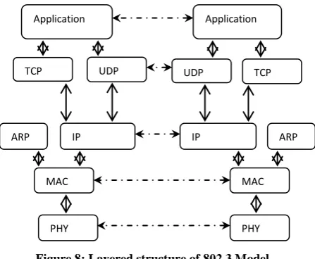
[image:3.595.51.279.428.544.2]The IEEE 802.3 model layered structure is shown in Figure 8.
Figure 8: Layered structure of 802.3 Model
LPC2148 is embedded with internal MAC but it does not support PHY layer. The Ethernet controller, ENC28J60 constitute for the MAC and PHY layer. So by interfacing with ENC28J60, the required PHY interfaced is achieved.
Table 1: Type 1 Ethernet frame E I/O
N C SCK 2
8 SI J SO
60
CS
SCLK
SDO M C SDI U
RJ45
Application Application
TCP UDP UDP TCP
IP ARP
MAC
PHY
IP ARP
MAC PHY Control Register s Flow Control Host Interface RMII Interf ace MIIM Interf ace P H Y T X R RXBM RXF (Filter)
DMA & IP CheckSum TXBM Ch0 Arbiter Ch1 8 Kbytes Dual Port RAM
Bus Interface
SPI System
Control Power on Reset Voltage regulator 25 MHz I/O SCK SDO SDI MCU INT0 INT1 TPOUT+ CS SCK SI TPOUT-
SO ENC28J60 TPIN+
TPIN- INT RBIAS WOL
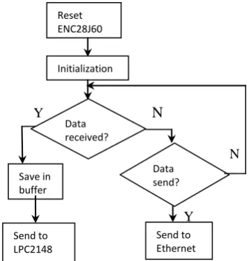
[image:3.595.320.544.502.686.2]LPC2148 when send data to ENC28J60 chip, it first get bound into UDP or IP packets and then passed to the data send buffer. On receiving data, by the Ethernet chip, firstly, CRC error checking is performed. If error is detected, the receive frame is deserted. If the data is error free, it is buffered to internal RAM and LPC2148 will process the received data as shown in Figure 9.
Y
N
N
[image:4.595.290.536.96.660.2]
Y
Figure 9: Data transmission and reception of ENC2860
4.
SYSTEM SOFTWARE DESIGN
The firmware development for the system operation is written in Embedded C language on Keil software. The program flow is shown in Figure 10. Here the user can either monitor the sensor data or control the device status by clicking the links given on the web page. The web page gets displayed for the client to access the equipments remotely once the IP address of the web server is entered in the web browser.
The Ethernet block of the system 10Mb/s or 100Mb/s Ethernet MAC that provides optimal performance through the use of DMA hardware acceleration. It has automatic frame transmission or reception with half or full duplex operation. The Ethernet block interfaces between the off-chip Ethernet PHY using Reduced MII protocol and the on-chip Media Independent Interface Management serial bus.
The Ethernet frame transmission flow chart is shown in Figure 11. Frame transmission and reception performed with Interrupt Service Queue operation.
Filtering of received frame, multicast and broadcast support for both frame transmit and receive, power management by clock switching, automatic collision back-off and frame retransmission are some of the features of the Ethernet controller used for network communication in this system.
N
Y
N
Y
Figure 10: Program Flow Chart
Pre- amble Start frame delimiter Dest address Source address Type of length Data Pad
Check
sum
7 bytes 1 byte 2-6 bytes 2-6 bytes 2 bytes 0-1500 bytes 0-46 bytes 4 bytes
Initialization
Send to Ethernet Send to
LPC2148 Save in buffer
Reset ENC28J60
Data received?
Data send?
Start
Initialize
LPC2148 ENC28J60
User in?
Requesting for application
Sensor 1 data
Sensor 2 data
Device1 status
Device2 status
User logout? ? Receiving
Information
Changing device status
[image:4.595.84.263.252.440.2]N
N
Y
Y
N
Y
N
[image:5.595.73.251.75.520.2]Y
Figure 11: Data frame send flow chart
4.1
TCP/IP Stack of EWS
This is one of the most widely used successful network protocol by which the control information can be passed. This protocol stack needs to be simplified to increase the speed of communication. Ethernet communication is achieved through the MAC address. With ARP, the physical address is obtained. Communication of the EWS the other equipments in the network could be achieved by the ICMP and IP especially for data routing. In the application the control of the remote host is to be undertaken and here comes the importance of HTTP protocol. In the transport layer, the TCP maintains the reliability of the communication.
4.2
Client Server Communication
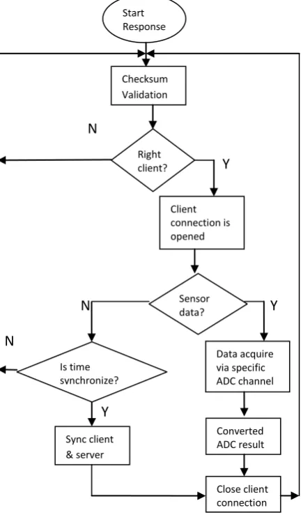
As we have seen before, when the client wants to access the equipments connected with the server remotely, it enters the configured IP address and it can monitor the equipment through the displayed HTML web page. For the communication to take place, before reception of data, initially CRC is performed with the checksum bytes. Once it
is identified that the checksum is valid, now it checks whether the user is the authorized one or not by comparing the logged in password with the stored password in the program. If the client is authorized one, now the system allows collecting data say sensor data through the specified ADC channel. Client server synchronization is performed at specific time intervals to get the most recent information. The program flow chart is shown in Figure 12.
N
Y
N Y
N
Y
Figure 12: Client Server Communication flow chart
4.3
HTTP Protocol
The protocol used for the communication between web server and web browser is Hyper Text Transfer Protocol or HTTP protocol. This protocol defines all the basic frame work of web communications by handling requests and also by providing control information to be transferred between browser and server. To obtain a web document, the browser and server should establish a connection at Port 80.
The transmission of HTTP is such as:
Establish a connection. To open a web document, client and server should establish their connection to port 80. This is done by means of sockets. Client will open a socket and bound it on a port. If successful, a virtual document is created where we can read and write.
Interrupt Invoked
Queue empty?
Return Interrupt
Read data frame
Send to upper software
Determine Physical Address
Data is send Get new data frame
Is data send?
If syn=1 & no overtime
Start Response
Checksum Validation
Client connection is opened
Converted ADC result Data acquire via specific ADC channel
Close client connection Sync client
& server
Right client?
Is time synchronize?
[image:5.595.320.538.166.539.2] Send the request. When connection is open, client can send request to the connected port of the server. Send response: Server can send response messages
after dealing with the client request.
Close connection: After the requested document is obtained, client and server can close the socket by closing the connection. Mostly server takes the initiative in closing the socket.
4.4
Socket
The work modes of web servers are based on socket mechanism. The combination of the network address and port defines a socket. Socket shields the underlying communication software with that of the operating system so that any two computers can communicate as long that they have installed the protocol and has realized the norms of the socket.
[image:6.595.319.500.126.299.2]In the server side, firstly the socket is created and it is bound to the server address. Now the socket is converted to listening socket to hear the client request. After this the connection to the client is established. To handle multiple requests, server carries out several processes that prevents the communication interference.
Figure 13: User access of EWS with external Ethernet
The front end of the EWS with external Ethernet controller is designed in Visual Basic and the IP the web page is opened by entering the pre-conf
ured IP address in the Hyper terminal with port no: 80. A snap shot is shown in Figure
[image:6.595.55.255.300.431.2]13.
Figure 14: Hardware of LPC1768 with integrated Ethernet.
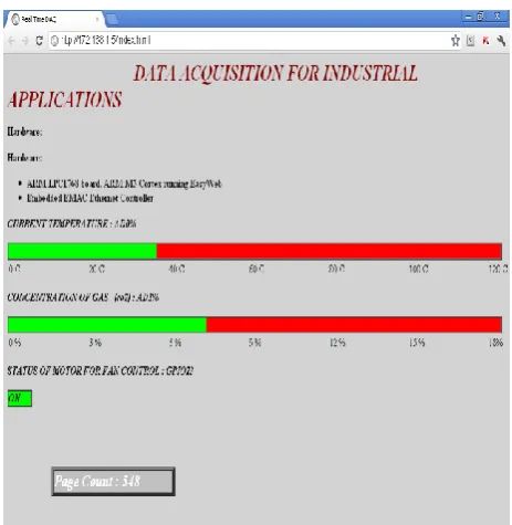
The HTML web page shown in Figure 15 shows the status of the temperature of the location to be monitored and also the CO2 gas concentration. The motor can be turned on or off by clicking the link provided in the web page. It shows the presence of an intruder in the remote area.
Figure 15: Web page of EWS with integrated Ethernet
5.
RESULT
[image:6.595.314.546.378.616.2]Figure 16: Hardware LPC2148 and Ethernet ENC28J60
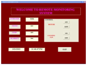
Also the front end designed in Visual Basic 6.0 for the remote access of the devices connected to the embedded web server with external Ethernet controller is shown in Figure 17.
Figure 17: Front end of the EWS with external Etherne
6.
CONCLUSION
The conclusion arrived after the performance analysis of the two systems is as follows.
Both the systems with integrated and external Ethernet interfaces are showing good performance. The system with integrated Ethernet is showing a bit more performance due to the chip level integration of Ethernet.
In the case of Ethernet controller, communication loss is there or delay in communication compared to the former mostly affected by the draw backs of serial communication.
When the case of monitoring multiple parameters comes, the EWS with integrated Ethernet is showing better performance when speed and reliability comes into picture.
Thus EWS with integrated Ethernet is suitable for real-time monitoring of Industrial appliances.
Moreover this systems has a wide variety of Industrial applications such as supervisory data control, Fault diagnosis, remote monitoring and controlling etc..
7.
ACKNOWLEDGMENTS
We express our sincere thanks to the faculties of Hindustan University, Chennai and the experts of ABE Technologies, Chennai for their support and guidance in the successful completion of the implementation of this system.
8.
REFERENCES
[1] Junhua Yang; Zhien Shang and Tao XinG, “Intelligence
Monitoring System Based on ARM and Information Fusion,” International Conference on Electric Information and Control Engineering, pp.487-490, April 2011.
[2] Karia, D.C., Adajania, V., Agarwal, M and Dandekar, S.; “Embedded Web Server Application Based Automation and Monitoring System,” International Conference on Signal Processing, Communixation, Computing and Networking Technologies, pp.634-637, July 2011.
[3] Manivannan, M and Kumaresan, N; “Design of On-line
Interactive Data Acquisition and Control System for Embedded Real Time Applications,” International Conference on Emerging trends in Computer and Information Technology, pp.551-556, March 2011.
[4] Zhao Ruimei and Wang Mei; “Design of ARM-based
Embedded Ethernet Interface,” 2nd
International Conference on Computer Engineering and technology, pp.V4-268-V4-270, April 2010.
[5] Zhai Wen-zheng and Hu Yue-li; “International Conference on Intelligent System Design and Engineering Application,” pp.506-509, Oct 2010.
[6] Zhan mei-qiong and Ji chang-peng; “Research and Implementation of Embedded Web Server,” Inetrnational Conference on Multimedia and Information Technology, pp.123-125, Dec 2008.
[7] Rui Yang, Hong Cai and Ming zhang; “Research and Implement of Ethernet Interface Based on Embedded System,” Second International Symposium on Computational Intelligence and Design, pp.288-291, Dec 2009.
[8] Wu Min-hua; “Research for the Embedded Web Server,” Microwave Conference, pp.776-779, Sept 2008.
[9] Masato Shimano, Futoshi Okazaki, Yoshihiro Saito, Akiya Fukui, Takako Nonaka and Tomohiro Hase; “Small, Embedded Web Server for Home Appliances with Embedded MPU and Real-time Operating Syatem,” pp.1-3, June 2007.
[10] Wu Xiguang, Li Bonian, Zhao Likai and Zhang Minghu; “An embedded real-time remote monitoring system based on B/S mode,” International Conference on Mechatronic Science, Electrical Engineering and Computer, pp.2135-2138, Aug 2011.
e-Learning Strategy,” 3rd
International Conference on Electronics Computer Technology, pp. 59-63, April 2011.
[12] Mo Guan and Minghai Gu; “Design and Implementation
of an Embedded Web Server Based on ARM,” IEEE International Conference on Software Engineering and Service Sciences,” pp.612-615, July 2010.
[13] Datasheet Reference Manual of LPC2148 processor.
[14] Datasheet Reference Manual of ENC28J60.