International Journal of Emerging Technology and Advanced Engineering
Website: www.ijetae.com (ISSN 2250-2459, Volume 2, Issue 7, July 2012)483
Experimental and Computational Analysis and
Optimization for Heat Transfer through Fins with
Triangular Notch
S. H. Barhatte
1, M. R. Chopade
21MIT College of Engineering, University of Pune, Pune 2 MIT College of Engineering, University of Pune, Pune
Abstract— Extended surfaces, commonly known as fins, often offer an economical and trouble free solution in many situations demanding natural convection heat transfer. Heat sinks in the form of fin arrays on horizontal and vertical surfaces used in variety of engineering applications, studies of heat transfer and fluid flow associated with such arrays are of considerable engineering significance. The main controlling variable generally available to designer is geometry of fin arrays. Considering the above fact, natural convection heat transfer from vertical rectangular fin arrays with triangular notch at the center have been investigated experimentally and theoretically. Moreover notches of different aspect ratio have also been analyzed for the purpose of comparison and optimization. In a lengthwise short array where the single chimney flow pattern is present, the central portion of fin flat becomes ineffective due to the fact that, already heated air comes in its contact. In the present study, the fin flats are modified by removing the central fin portion by cutting a triangular notch. This dissertation report presents an experimental analysis of the results obtained over a range of fin heights and heat dissipation rate. Attempts are made to establish a comparison between the experimental results and results obtained by using CFD software.
Keywords— Natural Convection, fin arrays, notches,
extended surfaces,ICEM-CFD, Fluent 6.3.
I. INTRODUCTION
Augmentation techniques are broadly classified as passive methods, which require no direct application of power or as active schemes, which require external power. Practically useful, augmentation techniques are, however, mostly passive ones.
Passive techniques are treated and structured surfaces, rough surfaces, extended surfaces, displaced enhancement devices, swirl flow devices, additives for liquids and gases, etc. Extended surfaces are widely used passive techniques to enhance heat transfer. Further enhancement in heat transfer can be obtained by proper selection of form of extended surface or by making some modifications in the geometry of surfaces like dent marks, grooved, or different types of notches etc.
II. NEED OF INVESTIGATION
Specially designed finned surfaces called heat sink, which are commonly used in the cooling of electronic equipment and stationary engines needs optimized design with minimum material and maximum heat transfer from them. In the natural cooling of fins, the temperature drops along the fins exponentially and reaches the environment temperature at some length. But heat transfer from the area near the tip is low. It results in wastage of material for small heat transfer rate. Cutting this portion of fins, results in the complete elimination of heat transfer from that region. Also the central portion of the fin flat becomes ineffective due to the fact that, already heated air comes in its contact.
In this investigation, the fin flats were modified by removing the central fin portion by cutting a notch of different geometrical shapes and adding it at the arrays entrance on the two sides, where it is more effective and thereby keeping fin surface area same.
The objectives of investigation are as listed below
1. To carry out study on fins with horizontal array and its analysis for natural convection.
2. To study influence of height to base ratio (aspect ratio) of triangular notch on heat transfer.
3. To determine dimensions of the notch for optimum heat transfer rate.
III. EXTENDED SURFACES
International Journal of Emerging Technology and Advanced Engineering
Website: www.ijetae.com (ISSN 2250-2459, Volume 2, Issue 7, July 2012)484
The rate of heat transfer from a surface at a temperature Ts to the surrounding medium at T0 is given by Newton’slaw of cooling as
)
(
Ts
To
hAs
Q
Where AS is heat transfer surface area, and h is the
convection heat transfer coefficient. When the temperatures TS and T0 are fixed by design considerations, as is often the
case, there are two ways to increase heat transfer rates 1. To increase convective heat transfer
coefficient h.
2. To increase the surface area AS.
Increasing h may require the installation of a pump or fan, or replacing the existing pumps or fans with a larger ones. This approach in some cases may or may not be practical. Besides in some cases, it may not be adequate. The alternative is to increase the surface area by attaching to the extended surfaces called fins made of highly conductive materials such as aluminum, copper etc.
IV. COMPUTATIONAL ANALYSIS
Temperature distribution and heat flux along the fin surface can be predicted by computational analysis. Apart from temperature distribution and heat flux various other parameters like Nusselt Number, heat transfer coefficient, and changes in other parameters can also be predicted by computational analysis.
Geometry is collected into a common geometry database (tetin file) which can be used by any of ANSYS ICEMCFD’s meshing modules. The mesh file is then imported into Fluent 6.3 solver for post processing. Computational analysis involves the application of heat transfer and fluid dynamics principles. Computational analysis involves three steps mainly modeling, preprocessing and post processing.
Fig. 1 Meshed model created in ICEM CFD
The discretization schemes used for this purpose are structured hexahedral grid mesh. With the hexahedral grid mesh the solution becomes more accurate. Scheme of tetrahedral grid mesh can also be used but it is less accurate. Moreover for regular geometry it is possible to use hexahedral grid mesh more efficiently and get more accurate results.
[image:2.612.337.547.284.431.2]Computational models for different aspect ratios were created and solved using the Fluent 6.3 solver. Solution for sets of fins of different aspect ratio was obtained. Fig 2 shows the plot of static temperature for the aspect ratio of 1.2667, similarly plots for other sets were also obtained. All the results are tabulated as given in the Table 1.
[image:2.612.50.275.556.689.2]Fig 2: Plot of the static temperature (aspect ratio 1.2667)
Fig. 3 Variation of Heat Flux Along Fin Length
Table I
Results of CFD analysis
SET Heat Transfer Co-efficient
Trial 1 Trial 2 Trial 3 Average
SET 0 5.696 5.657 5.721 5.6913
SET 1 6.102 6.062 6.07 6.078
SET 2 6.111 6.072 6.11 6.0976
SET 3 6.130 6.116 6.072 6.106
SET 4 6.38 6.46 6.43 6.4233
International Journal of Emerging Technology and Advanced Engineering
Website: www.ijetae.com (ISSN 2250-2459, Volume 2, Issue 7, July 2012)485
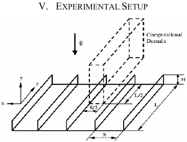
The variation of heat flux along the length of fins is obtained as expected and also as can be seen from computational analysis, the value of h is maximum for set 4, i.e. set with aspect ratio of 1.266. [image:3.612.305.558.149.731.2]V. EXPERIMENTAL SETUP
Fig. 4 Schematic of the experimental setup
Fig. 5 Experimental setup
As shown in Fig 3, the experimentation shows a Chimney-Like Flow Pattern, the fact is also supported by the computational analysis as can be seen in the Fig 2.
VI. PROCEDURE FOR CALCULATION A. To find average temperature of base plate (Tb)
2
2
1 b
b b
T
T
T
---1where, Tb1 & Tb2 are the temperatures of base plate at two points in ° C.
B. To find average temperature of fins(Tf )
5
5 4 3 2
1 f f f f
f f
T
T
T
T
T
T
---2where,
Tf1, Tf2,Tf3, Tf4 & Tf5 are the temperatures of fins in ° C.
C. To find temperature of whole body (Tbody)
2
f b body
T
T
T
---3D. To find temperature difference between body & surrounding temperature (δT)
surr body
T
T
T
---4E. To find mean film temperature (TLm)
273
2
body surr lmT
T
T
---5F. To find coefficient of volume expansion (β) 1
1
k
T
lm
---6To find Grashof number (Gr)
2 3
g
TL
c ---7Where,
Lc= characteristic length of the geometry, m
υ = kinematic viscosity of the fluid , m2/s
Pr = Prandtl number
k = thermal conductivity of fluid , W/mk
G. To find Rayleigh number (Ra)
Ra = Gr . Pr ---8
If 104 < Gr.Pr < 109 then , Nu = 0.59 (Gr.Pr)1/4
If 109 < Gr.Pr < 1012 then, Nu = 0.59 (Gr.Pr)1/3
H. To find Nusselt number (Nu)
---9
I. To find heat transfer coefficient (h)
K
hL
Nu
c ---10 [image:3.612.77.260.193.332.2]International Journal of Emerging Technology and Advanced Engineering
Website: www.ijetae.com (ISSN 2250-2459, Volume 2, Issue 7, July 2012)486
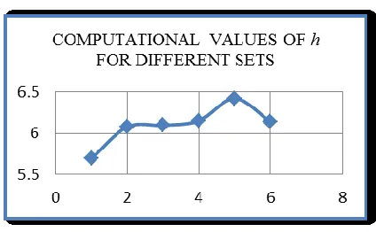
After performing rigorous experiments, results were tabulated and a comparison was made and a graph was obtained as shown in Fig 5, which clearly shows effect of aspect ratio on h and also the fact that h is maximum for the set4 of aspect ratio 1.2667. [image:4.612.326.562.217.338.2]VII. RESULTS
[image:4.612.70.284.229.349.2]Fig. 6 Average Experimental Value of h versus Aspect Ratio
Fig. 7 Average Computed Value of h versus Aspect Ratio
Fig. 8 Comparison of Experimental and Computational Values of h
It is a proven fact [2] that heat transfer coefficient and in turn the heat transfer rate is maximum for the fins with triangular notch. For fins with triangular notch, it is observed that the value of heat transfer coefficient h goes
on increasing with increasing aspect ratio and after a particular threshold value of aspect ratio, it then goes on decreasing as can be seen from the Table2.
Table II
Experimental and Computational Values of h
SET Aspect Ratio Experimental Value of h Computational Value of h
SET 0 Unnotched 6.495 5.691
SET 1 0.866 6.505 6.078
SET 2 1.000 6.517 6.097
SET 3 1.333 6.532 6.152
SET 4 1.266 6.545 6.423
SET 5 1.400 6.494 6.137
VIII. CONCLUSION
Following points are worth noting from the present investigation work.
1. Computational analysis and subsequent experimental investigations have revealed fins can be used effectively to enhance the rate of heat transfer.
2. It is also revealed that heat transfer coefficient and in turn the rate of heat transfer can further be increased by increasing the surrounding fluid velocity i.e. by forced convection.
3. The performance of heat transfer fins can be analyzed effectively by commercially available CFD software, Fluent 6.3 in specific.
4. It is proved beyond doubt that the heat transfer coefficient is highest for the set of fins with triangular notch.[2] Further, h increases with increasing aspect ratio and then decreases after a threshold value of 1.266. This has been shown by the CFD analysis as well as by the experimental analysis.
The same methodology of experimental investigation and computational analysis can be used further for different types of notches and fins.
IX. SUGGESTIONS FOR THE FUTURE WORK
[image:4.612.70.282.373.504.2]International Journal of Emerging Technology and Advanced Engineering
Website: www.ijetae.com (ISSN 2250-2459, Volume 2, Issue 7, July 2012)487
understood that the rate of heat transfer is increased by having a notch at the centre of fin. The computational analysis did not indicate of any particular shape of notch which would give maximum heat transfer.It was only our presumption of considering only the commonly available shapes like circular, rectangular, triangular, and trapezoidal. Although the current investigative study reveals that there is maximum heat transfer for triangular notches, probably there would be other shapes for which the rate of heat transfer would be maximum. Current study also helped in finding the size of notch for maximum heat transfer. In future study a similar exhaustive experiments may be performed for finding a correlation between heat transfer rate and the aspect ratio. The results so obtained may also be validated by computational analysis.
REFERENCES
[1] Bejan A. and Morega A. M., “Optimal Arrays of Pin Fins and Plate Fins in Laminar Forced Convection”, J. Heat Transfer, Vol 115, pp. 75-81.
[2] Barhatte. S. H, Chopade. M. R, Kapatkar V. N, “Experimental and Computational Analysis and Optimization for Heat Transfer through Fins with different types of Notches”, Journal of Engineering Research and Studies, Volume II, Issue I, January-March 2011.
[3] Poulikakos, A. and Bejan, A., “FinGeometryforMinimumEntropy Generation in ForcedConvection” ASME Journal of Heat Transfer, Vol 104, pp. 616-623.
[4] W. W. Lin and D. J. Lee, “Second-law analysis on a flat plate-fin array under crossflow” International Communications in Heat and Mass Transfer, Volume 27, Issue 2, February 2000.
[5] Islam Md. Didarul, Oyakawa Kenyu, Yaga Minoru and Senaha Izuru, “Study on heat transfer and fluid flow characteristics with short rectangular plate fin of different pattern” Experimental Thermal and Fluid Science, Volume 31, Issue 4, February 2007.
[6] P. R. Kulkarni, “Natural Convection heat transfer from horizontal rectangular fin arrays with triangular notch at the center.” Paper presented at NCSRT-2005. (Nov 18-19, 2005), Pg. No.: 241-244.
[7] Yunus A. Çengel, 2004, “Heat Transfer- A Practical Approach”, SI units 2nd Edition, Tata McGraw Hill Co., Pg. No. : 156-168, 333-352 & 459-500