Construction Application Protocol for Data Transfer:
A Building Data Model
Che Wan Fadhil Che Wan Putra
T.I.M.E. Research Institute
Department of Surveying
University of Salford, Salford, UK
Table of Contents
List of Tables
List of Figures
Acknowledgements
Abbreviations
Abstract
Chapter 1: Introduction
1.1 Introduction 1
1.2 The research background 5
1.3 Research hypothesis 9
1.4 Aims of the research 9
1.5 The objectives of the research 10
1.6 Methodology of the research 12
1.7 Scope of the research 14
1.8 Guide to the thesis 15
Chapter 2: Information Management and the Project Life Cycle
2.1 Introduction 18
2.2 Project life cycles stages 19
2.2.1 Conceptual stage 21
2.2.4 Construction stage 23
2.2.5 Occupation/Maintenance stage 24
2.3 Procurement methods and the role of professionals 24
2.4 Integration problems 25
2.5 Project co-ordination, the needs and benefits 27
2.6 Project information and information technology (IT) 29
2.7 Managing the flow of information 31
2.8 Summary 33
Chapter 3: Information Sharing and Integrated Environment
3.1 Introduction 34
3.2 Information sharing and the implementation 35
3.2.1 Islands of automation and the need for information sharing 38
3.3 Approaches to integration 39
3.3.1 Definition of integration 40
3.3.2 Approaches to data exchange 42
.3.4 Current approaches to integrated environments 46
3.5.1 Computer Integrated Manufacturing (CIM) 47
3.5.2 Computer Integrated Construction (CIC) 49
3.5.3 Concurrent Engineering (CE) 51
3.5 The needs for standards 54
3.6 Summary 55
Chapter 4: Data Exchange and Standards
4.1 Introduction 57
4.2 Data exchange: Definition and classification 58
4.3 Data exchange: Problems and formats 60
4.3.1 EDI formats (Non-Geometric data) 61
4.3.2 IGES formats (Geometric data) 64
4.3.3 DXF format (Geometric data) 65
4.3.4 STEP format (Geometric data) 66
4.4 Data protocols 67
4.4.1 STEP protocols (APs) 68
4.4.1.1 STEP architecture 68
4.4.1.2 STEP integrated resources 70
4.4.2 Application Protocols (APs) 72
4.5 An international dimension to data exchange standards:
The International Alliance for Interoperability (IAI) 75
4.5.1 Industry Foundation Classes (IFCs) 76
4.5.1.1 Benefits of IFCs 77
4.5.1.2 Structure/Model of IFCs 77
4.5.1.3 IFCs object model 78
4.6 Summary 79
Chapter 5: Product Modelling and the Integrated Environment
5.1 Introduction 82
5.2 Information modelling approach 83
5.2.1 Activity model 84
5.2.2 Data model 86
5.3 Definition and importance of Product Modelling 88
5.4 Information modelling techniques 90
5.4.1 The SADT method 90
5.4.2 The EXPRESS and EXPRESS-G method 94
5.4.2.1 EXPRESS 94
5.4.2.2 EXPRESS-G 95
5.5 Product Models in an integrated environments 97
5.5.1 RATAS 98
5.5.2 ICON 100
5.5.3 ATLAS 102
5.5.4 GenCOM 105
5.5.5 COMBINE 106
5.5.6 OSCON 108
5.5.7 WISPER 108
5.6 Summary 109
Chapter 6: The Proposed Integrated Construction Environment
6.1 Introduction 111
6.2 A generic framework for integrated environment 113
6.2.1 The Context Diagram (A-0) 114
6.2.2 The decomposition of the Context Diagram (AO) 116
6.2.3 Define Product and Other Data Models (Al) 118
6.2.4 Build and Integrate Applications (A2) 121
6.2.5 Apply Project Specific Information (A3) 122
6.3 Data structure 123
6.4 The implementation of the proposed framework 125
6.4.1 The Project Model 126
6.4.2 Software Packages and External Databases 128
6.5 SPACE 129
6.5.1 CAPE 131
6.5.2 SPECIFICATION 131
6.5.3 CONPLAN 132
6.5.4 EVALUATOR 133
6.5.5 INTESITE 133
6.5.6 CONVERT 134
6.6 The working environment 134
6.7 Benefits of SPACE 135
6.8 Summary 136
Chapter 7: Object Definition in an Integrated Construction
Environment
.7.1 Introduction 138
7.2 Problems with the implementation of data models 139
7.3 Objects and dependent-objects 141
7.4 Object's definition 142
7.4.1 Global data 144
7.4.2 Specific data 147
7.5 The proposed framework for object's life cycle 148
7.5.1 Create and amend object 149
7.5.3 Use object 152
7.5.4 Decommission object 153
7.6 Data required by an object over its life cycle 154
7.7 Multiple view provider 158
7.8 Definition of a wall object 160
7.9 Summary 166
Chapter 8: CAPE: The Building Elements Data Module
8.1 Introduction 168
8.2 EXPRESS-G models and notations 170
8.2.1 Graphical symbols 170
8.3 Developing the EXPRESS-G model 174
8.3.1 Phase 1: Basic objects 176
8.3.2 Phase 2: Relationships and attributes 177
8.3.3 Phase 3: Completion and constraints 179
8.3.4 Phase 4: Model integration 180
.8.4 The context diagram — High level view of a project presentation 181
8.5 The Level 1 diagrams 182
8.5.1 The "Project Type" entity 183
8.5.2 The "Building" entity 184
8.6 The Level 2 diagrams 187
8.6.1 The "Building Space" entity 187
8.6.2 The "Building Other Specifications" entity 190
8.6.3 The "Building Elements" entity 192
8.6.4 The "Building Design" entity 196
8.7 Relationship between the "Building Elements" data module and
other modules in the ICE 199
8.8 Summary 207
Chapter 9: CAPE: System's Development
9.1 Introduction 209
9.2 System's architecture 210
9.2.1 The system input 212
9.2.2 The knowledge-based of CAPE 212
9.2.3 The graphical interpretation of the system's information 216
9.3 The system's implementation 218
9.3.1 The CAD system 219
9.3.1.1 Object Interpreter Engine (OIE) 219
9.3.1.2 Graphical File Generator 233
9.3.1.3 Space Analyser 235
9.3.2 The object-oriented environment 241
9.3.2.1 Object analysis 242
9.3.2.2 Space analysis 252
9.4 System's application 258
9.4.1 Application of an object through their life cycle 258
9.5 Summary 262
Chapter 10: Demonstrating and Experimenting with the Prototype
10.1 Introduction 263
10.2 Demonstrating the prototype 264
10.2.2 Topological relationships 269
10.2.3 Space definition 270
10.3 Experimenting with the prototype 275
10.3.1 The experimental approach 275
10.3.2 Validation of the prototype systems 280
10.4 Summary 281
Chapter 11: Summary and Conclusions
11.1 Introduction 283
11.2 Summary of the research work 284
11.3 Main conclusion 292
11.4 Recommendations for future work 295
11.5 Recommendations for the industry 297
References 299
List of Tables
Table 3.1 Types of project information: the implications of sharing
[Amended from DETR, 1996] 37
Table 4.1 Examples of STEP Application Protocols for construction 74
Table 4.2 IFCs model overview [TAT, 1996] 79
Table 7.1 Global and Specific Data of object definition 145
Table 9.1 AutoCADAECTM layer naming convention [AutoDesk, 1993] 221
Table 9.2 The cavity wall entity cross-reference scheme [Amended from
Figure 1.1 Research methodology 13
Figure 2.1 Traditional project life cycle 20
Figure 2.2 Traditional fragmented and sequential project delivery process 28
[Amended from Teicholz and Fischer, 1993]
Figure 3.1 Direct translator approach 42
Figure 3.2 Standard exchange approach (neutral file) 43
Figure 3.3 Blackboard architecture [Amended from Westinghouse, 1997] 44
Figure 3.4 Product model approach 45
Figure 3.5 Computer integrated construction [Amended from Goldscmidt &
Navon, 1996] 49
Figure 3.6 Concurrent Engineering approach to the project life cycle
[Amended from Alshawi, 1996] 53
Figure 3.7 The traditional approach [Amended from Alshawi, 1996] 54
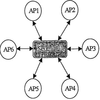
Figure 4.1 Neutral file format data transfer 61
Figure 4.2 The evolution of data exchange format [Bloor & Owen, 1994] 65
Figure 4.3 STEP schema architecture [Yang, 1991] 69
Figure 4.4 STEP Integrated Resources [Yang, 1991] 71
Figure 4.5 A portion of the STEP Building Construction Core Model
[Froese, 1995] 73
Figure 5.1 The Context Diagram and its decomposition
[Grabowski, 1991; Marca, 1988] 92
Figure 5.2 The hierarchical structure of SADT diagram
[Grabowski, 1991; Marca, 1988] 93
Figure 5.3 A small example schema illustrating the symbols used in
EXPRESS-G [BjOrk, 1992c] 96
Figure 5.4 An illustration of the levels used in the RATAS system
Figure 5.5 Figure 5.6 Figure 5.7 Figure 5.8 Figure 6.1 Figure 6.2 Figure 6.3 Figure 6.4 Figure 6.5 Figure 6.6 Figure 6.7 Figure 7.1 Figure 7.2 Figure 7.3 Figure 7.4 Figure 7.5 Figure 7.6 Figure 8.1 Figure 8.2(a) Figure 8.2(b) Figure 8.3(a) Figure 8.3(b) Figure 8.4 Figure 8.5 Figure 8.6 Figure 8.7
A portion of the ICON Construction Planning Object Model [Aouad et al, 1994]
Relation between the different ATLAS models
[Tolman & Poyet, 1995]
A portion of the ATLAS LSE project type model [Tolman et al, 1994]
A portion of the high-level object types from the GenCOM
conceptual model of construction [Froese, 1992]
The Context Diagram of A-0
The decomposition of the Context Diagram (A-0) — AO
Define Product and Other Data Models — Al
Build and Integrate Applications — A2
Apply Project Specific Information — A3
Typical models of the ICE
Conceptual representation of the ICE
3D geometric information of typical building elements
Process modelling of object's life cycle
Data required by the object's over their life cycle
The concept of providing multiple views
The algorithms of the first three stages of the proposed object
Definition over the life cycle
Defining a wall object over its life cycle
Symbols for an entity and a schema
Simple type symbols
Type definition symbols
Relationship line styles
Open circle showing the to end relationship
Composition symbols
Context Diagram — High level view of the project information
(page 1 of 10)
Level 1 diagram — Project Type (Page 2 of 10)
Level 1 diagram — Buildings (Page 3 of 10)
101 103 104 106 114 115 118 120 122 124 127 147 151 155 162 164 165 171 172 172 172 173 174 182 183 185
Figure 8.9 Figure 8.10 Figure 8.11 Figure 8.12 Figure 8.13 Figure 8.14 Figure 8.15 Figure 8.16 Figure 8.17 Figure 8.18 Figure 8.19 Figure 9.1 Figure 9.2 Figure 9.3 , Figure 9.4 Figure 9.5 Figure 9.6 Figure 9.7 Figure 9.8 Figure 9.9 Figure 9.10 Figure 9.11 Figure 9.12
Level 2 diagram — Building Space (Page 5 of 10)
Level 2 diagram — Building Other Specifications (Page 6 of 10)
Level 2 diagram — Building Elements (Page 7 of 10)
Level 2 diagram — Part entity-model of Building Elements —
Topological Relationships (Page 8 of 10) 194
Level 2 diagram — Part entity-model of Building Elements —
Wall (Page 9 of 10) 196
Level 2 diagram — Building Design (Page 10 of 10) 197
Part of EVALUATOR data model [Underwood & Alshawi, 1997] 200
Part of SPECIFICATION data model [Underwood & Alshawi,
1997] 202
Part of CONPLAN data model [Hassan, 1997] 203
Part of INTESITE data model [Sulaiman, 1997] 206
An overview of CONVERT prototype environment
[Alshawi & Faraj, 1995] 207
CAPE system architecture 210
General overview of the processes in the CAD system 213
General overview of the processes in the object-oriented
environment 215
Building elements shown in VR 217
Topological relationships between pad foundation and other
structural elements 217
Space boundaries and floor surface finishes 218
Steps for the implementation of OIE 220
The representative object for a cavity wall [Amended from
Ewen & Alshawi, 1993] 227
Topological relationships between elements and their
intersection 230
The topological relationship snap-shot 232
Updates DXF file for complex elements 234
Analysing a space 236
186
188
190
191
Figure 9.13 An example of identifying a complex space 237
Figure 9.14 An example for analysing the space boundaries 239
Figure 9.15 The relationship between space 241
Figure 9.16 Object hierarchy in KAPPAPCTM 243
Figure 9.17 An example of cavity wall instance with their slots and values 244
Figure 9.18 Cavity wall instance, which cross-referenced with the
Specification module 245
Figure 9.19 Detail of specification instance and specification database 246
Figure 9.20 A cavity wall instance with "attached to" slot and their content 248
Figure 9.21 A square column instance which is supported by other square
column 249
Figure 9.22 Relationship between a simply supported beam instance with
actual instance in the building elements data module 250
Figure 9.23 Relationship between a continuous beam instance with actual
instance in the building elements data module 251
Figure 9.24 Space boundary with wall surface finishes specification 252
Figure 9.25 Space object with floor finishes specification 253
Figure 9.26 Space object with space separator and space opening 255
Figure 9.27 Space separator including cavity wall and flat slab 256
Figure 9.28 Space object which associated with space boundaries objects 257
Figure 9.29 Space boundary which associated with space separator
(cavity wall) 257
Figure 9.30 Application of an object through their life cycle 259
Figure 10.1 Main screens of SPACE with CAPE demonstration menu 264
Figure 10.2 Elements display by material specification 266
Figure 10.3 Selection of beams in all storey/level 267
Figure 10.4 Total cost of selected storey 268
Figure 10.5 Structural elements of a building 269
Figure 10.6 Effected structural elements when a pad foundation is deleted 270
Figure 10.7 The associated structural elements with a selected column 271
Figure 10.8 Main menu screen for defining a space in CAPE 272
Figure 10.9 CAPE queries window for space demonstration 272
Figure 10.10 Highlighting the space boundaries of a living room 273
First of all, I would like to thank all those who helped with the work undertaken in this
study especially
to:-> The Government of Malaysia and my employer, Universiti Teknologi Malaysia for
providing me the financial support and the opportunity to further my study.
> My superior supervisor, Prof. Dr. Mustafa Alshawi, for his valuable guidance,
unfailing support, encouragement, readiness to help and many things, in which
without them this study can never succeed.
> Thanks to all members of the AIC Group for their helpful instructions, discussion,
and comments in the development of this study especially to Dr. Ihsan Faraj, Dr.
Jason Underwood, Dr. Mohamad Jamil Sulaiman, Dr. Zainudin Hassan and last but
not feast to Dr. Ghassan Aouad for his comments during weekly workshop.
> Dr. Syed Alwee Syed Alsagof for his comments while preparing this thesis and also
to Dr. Mushairy and his wife for their proof reading of the thesis.
Finally, I would like to dedicate my thanks to my lovely parents especially my wife,
Rosmina, for her patience and continuous support over the years, my sons, Fareez and
AEC Architectural Engineering and Construction
AIC Automation and Integrated Construction
ANSI American National Standard
APs Application Protocols
BCCM Building Construction Core Model
BQ Bill of Quantity
B-Rep Boundary Representation
CAD Computer Aided Design
CAPE Construction Application Protocols for Comprehensive Data Transfer
CE Concurrent Engineering
CIC Computer Integrated Construction
CIM Computer Integrated Manufacturing
COMBINE Computer Models for the Building Industry in Europe
CONPLAN Intelligent Construction Planning Generator for Design Rationalisation
CONVERT Construction Virtual Environment
CSG Constructive Solid Geometry
DBMS Database Management Systems
DDE Dynamic Data Exchange
DETR Department of Environment, Transport and the Regions
DFD Data Flow Diagram
DXF Data Exchange File
EDT Electronic Data Exchange
ERD Entity Relationship Diagram
EVALUATOR Project Estimate and Interim Valuations (Monthly) Generation in an
Integrated Environment
TAT International Alliance for Interoperability
ICE Integrated Construction Environment
ICON Integration of Construction Information
IDEF0 ICAM Definition Method Zero
IFCs Industry Foundation Classes
IGES Initial Graphics Exchange Specifications
INTESITE Intelligent Site Layout Planning
ISO International Standard Organisation
IT Information Technology
NBA The National Building Agency
OFD Object Flow Diagram
PM Product Model
PMI Project Management Institute
MBA Royal Institute of British Architects
SADT Structured Analysis and Design Technique
SPACE Simultaneous Prototype for an Integrated Construction Environment
STEP Standard for Transfer and Exchange of Product Data Model
VR Virtual Reality
,
Construction is a process, which involves diverse parties having different
professional skills and interest. At present, the co-operation and information exchange
between parties involved in any construction has not yet been attained. During a project
life cycle, the amount of information generated and exchanged is enormous even for a
small-size construction project. Current process of managing information flow in
construction still lags behind other industries such as manufacturing.
In the era of information age, information technology (IT) becomes a vital tool for
managing information. It allows a user/manager to store and retrieve information
easily, quickly, produce complete and accurate response, and be better informed of the
relevant issues. However, the progress of IT in the construction industry relies on the
ability of the project participants to exchange and share information among themselves.
Inevitably, there is a need for common standards and approaches due to the lack of
compatibility of the information exchange.
The complexity and vast amount of information involved in any construction
project and the lack of standards have made the process of producing an integrated
environment very difficult. A framework for establishing an Integrated Construction
Environment (ICE) has been proposed with the aim of co-ordinating the integration
process between the various construction applications. SPACE (Simultaneous
Prototyping in An integrated Construction Environment) has been developed which
aims to integrate design and construction throughout the project's life cycle via a single
The implementation of this framework has led to the development of a modularised
central core whereby each application has its own data module. CAPE (Construction
Application Protocol for data transfEr) is a design application, which has been
developed as part of data module in SPACE. It represents a building elements data
module and the object interpreter engine. It aims is to improve the flow of information
between project's participants, particularly those related to the design stage.
The development of CAPE data module has resulted in the implementation of a
system, which capture most of the design elements in CAD (AutoCAD/AEC Tm), the
study of their properties such as co-ordination and dimension and populates it into the
object-oriented database systems to serve other application modules in the project
model, i.e. SPACE. CAPE data module also provides several benefits. It provides
essential support for the integration of design and construction, a generic set of building
element classes, defines building elements with the necessary information at run-time,
and a dynamic and an independent environment for all graphical packages such as
CAD and YR.
Chapter 1
Introduction
1.1 Introduction
Construction projects proceed through a series of phases during their life [Sanvido,
1992a]. These project life cycle phases have been classified as manage, plan, design,
construct, and operate functions [Sanvido et al., 1990]. Information is one of the key
elements that drive these processes. During a project life cycle, the information is
passed from one phase to another. In a large project, there are substantial volumes of
information flow between the various players during the design and construction of a
particular project [Watson, 1995]. As a result of this, there is an increase of information
processing. Sanvido [1992a] has highlighted some of the major factors, which led to the
increase of information processing requirements for the project team as follow;
The market place often dictates that projects are required in increasingly shorter
time periods. This typically requires concurrent design and higher staffing levels.
Chapter 1
The product requirements may be changed several times during a project's life
cycle in order to serve the client's need. As a result, there is an increase in the
information processing requirements whereby all these changes need to be
communicated to the specialists at various stages of the process.
The information processing in the construction industry, which involves diverse
parties having different professional skills and interest [Munns, et al., 1995], requires
the parties to co-operate and exchange information in order to complete the building
project. However, this is not yet successfully implemented. Many participants are
involved in the construction project such as contractors, sub-contractors, suppliers, etc.
rarely undertake their responsibility on site [Keijer, 1992]. These participants tend to
operate from their perspectives and not from the whole project perspective, thus
resulting in local optimal solutions. Furthermore, many participants who specialised in
construction and have different views of the process have drifted apart and are often
geographically isolated from each other [Aouad, et al., 1994]. These have resulted in
the fraginentation of the construction industry itself [Howard et al., 1989]. The
fragmentation exists both within individual phases of the construction process (e.g. the
design phase), as well as across project phases from planning through design and
construction and into facility maintenance and operation. Brandon and Betts [1995]
stressed
that:-"fragmentation refers to the fact that the different participants in the design and construction of buildings have been trained, and gained experience, through different educational and professional paths, are employed in distinct organisations, have distinct value systems and methods of working, and have derived separate information management systems. Information management, because of this, is highly fragmented"
As a result of the fragmentation of the AEC industry, generating, sharing, and
maintaining project information throughout a project life cycle constitute a complex
assignment [Howard et al., 1989]. Several professionals from various organisations
receive and utilise project information, producing additional information and
contributing to the evolution of AEC projects [Kartam, 1994]. These numerous
numbers of professionals involved in several stages of an AEC project have led to
decreased integration, co-ordination and collaboration among the participants. As a
consequence of the lack of industry integration, professionals responsible for one
specific AEC project phase depend on information relative to other phase to be able to
perform their functions. These lead to problems, for instance, incomplete specifications
and design, changes in site conditions, misinterpretation of contract documents,
unconstructable designs, etc.
Both horizontal and vertical flows of information are essential for lessening
prejudicial effects of industry fragmentation [Kartam, 1994]. Horizontal flow of
information is the communication among professionals of different disciplines involved
in one specific project phase. For instance, during the design phase, structural and
electrical engineers, along with several other professionals, are working simultaneously
on different plans of the same project and the communication between them are
indispensable. Vertical flow of information, on the other hand, means the exchange of
information between professionals of different disciplines involved in different project
phases. For instance, communication between construction managers and architects is
fundamental for project accomplishment. Therefore, extensive flow of information, i.e.
both horizontal and vertical is vital aspect when trying to increase industry efficiency.
Chapter I
Construction is an information intensive industry that will gain large benefits from
the automation of its information flow and the creation of shared knowledge [DETR,
1996a]. By sharing the information, the construction industry will gain many benefits
such as increasing productivity, improving quality, etc. [Tah et al, 1994]. However,
current approaches of information sharing in the construction industry suffer many
problems. These problems arise due to the bulk of these information flows which are
still in the form of traditional paper drawings [Watson, 1995]. This often leads to the
difficult flow of information, substantial loss in efficiency of design, planning, and
construction phases of a project, as well as increased potential for errors [Kartam,
1994]. A recent study by DETR [1996a] also highlighted some of these problems such
as:-o Difficulty in cas:-odifying infas:-ormatias:-on;
o Loss of information at the end of projects;
o Lack of facilities to store information;
Today, in the emergence of information technology (IT), most project information
is stored and processed on computers. These may include CAD systems, structural
analysis/design packages, project management packages, etc. However, the presence of
these software packages tend to solve specific problems and business needs only. Most
of the packages are stand-alone which results in 'island of automation' within the
industry. Therefore, by integrating project participant's computer systems, the
effectiveness of a project team will be greatly enhanced, i.e. by increasing data sharing,
reducing time requirements and errors for data input and output, accelerating
communication among participants, and improving the completeness of information
received by each team member [Fischer & Froese, 1992].
The word 'integration' has become very widely used to describe the desirable
concept of freely exchanging information between different participants in the
construction process, yet actual examples of integration are relatively limited and
localised [Vincent, 1995]. Today, effective integration requires the continuous and
interdisciplinary sharing of project goals, data, and knowledge among all project
participants [Fischer & Froese, 1992]. Such integration requires an agreed framework
whereby the information can be integrated. Many researchers believe that such
framework can be achieved through an integrated environment [Yamazaki, 1992; Faraj
& Alshawi, 1996; BjOrk, 1992; Teicholz & Fischer, 1993; Iosifidis et al., 1995]
whereby all possible construction applications can be integrated under one
environment. However, the complexity and the vast amounts of information involved in
any construction project and the lack of standards, have made the processes of
producing an integrated environment very difficult [Sanvido, 1992b; Faraj & Alshawi,
1996; Aouad & Price, 1993]. Until now, the question of how such framework of an
integrated environment should be structured and implemented effectively still remains
to be further investigated.
1.2 The research background
The construction industry by nature is a transient and highly fragmented industry
and because of these two characteristics, co-ordination and proper communication have
significant effect on productivity and quality of construction project [Sadri & Kangari,
1993]. In the construction industry, the planning, design and construction activities are
typically carried out by participants in different organisations. These various stages are
Chapter I
described in R.I.B.A Plan of Work [RIBA, 1980], whereby each stage of the project life
cycle contain processes which are executed by a specific profession, i.e. designers,
contractors, etc. Due to the large number participants involved in the project life cycle,
the lack of proper communication, information sharing and exchange exist. During the
last three decades, there have been several attempts to find the solution for the above
mentioned problems. A large number of researchers looked for ways of improving the
communication between the different parties involved and in particular, to enhance the
flow of a project's information. In recent years, integrated systems and information
integration have shown to have many promises towards solving complex problems such
as those in the construction industry [Howard et al., 1989; Aouad et al., 1994; Fischer
& Froese, 1992].
'Integration' is sometimes quoted as having happened when any substantial
amount of information has been exchanged in digital form [Vincent, 1995]. Exchanging
electronic drawings, for example, may actually offer little improvement over
exchanging paper drawings whereby it still requires a skilled eye to interpret them.
Historically, the UK construction industry has been reluctant to take the initiative
regarding moves towards the integration of construction information [Watson, 1995].
Although many different application programs are in use, there has been relatively little
provision for transferring information between them. The consequences of this result
from two folds, i.e. the contractual nature of the construction industry and the 'islands
of automation' in which each application's programs are isolated between each
construction discipline.
Several efforts have been devoted towards the development of a framework for an
integrated environment in the construction industry. However, the successful
development and implementation of Computer Integrated Manufacturing (CIM)
(improving time, cost and quality) has led to the development of Computer Integrated
Construction (CC). CIC consists of both of the use of information technology in the
different phases and tasks in construction, and the integration of these phases and tasks
through the use of digitally stored data and data transfer [Bjärk, 1992]. CIC can address
the needs and requirements of all parties involved in a project life cycle [Alshawi,
1993].
It has been recognised widely that in order to achieve the best performance, such
integrated systems need to share and exchange data through a single core, i.e. a product
model [Alshawi & Che Wan Putra, 1995]. The product model is the core of any CIC
environment whereby a library of objects is formed from which a symbolic project
model can be built up [Levitt et al, 1991]. Such a symbolic model can capture the
various 'components of a project such as walls, beams, etc., their properties e.g.
thickness, length, etc., and their relationship with each other e.g. embedded in,
supported by, attached to, etc.
Although the industry have witnessed the integrated systems to be the better
solution of the fragmented construction, the main problem would be the compatibility
of the integrated information generated between each participants. Therefore, an agreed
standards are required for the integration of the various disciplines involved. The most
important is the data exchange format. Although the issue of a standard neutral data
exchange format has started since late 70's, the initiative of establishing the
Chapter I
international standards for exchanging data between applications such as STEP by the
International Standard Organisation (ISO) at late 80's has been welcomed world-wide,
especially in the construction industry. However, these standards have been
materialised in the form of data modelling and data representation and not into
protocols for data transfer [Alshawi & Che Wan Putra, 1995]. Application Protocols
(APs) committees have been established to meet the increasing demand for establishing
a format to transfer project specific information. However, implementation problems
are quite different from theoretical data modelling and can reveal significant
weaknesses in any theoretical development. Therefore, best results can only be
achieved through a simultaneous consideration of theoretical data modelling and
practical implementation.
In order to overcome the above-mentioned problems, two main issues which are
related to information management and information flow within and among the various
data models in an integrated environment i.e. object definition and data sharing are
studied. Object definition is the most efficient number of attributes an object can be
populated with, in order to serve all possible construction applications efficiently and
effectively. While shared data is a common data, which serves the interest of a number
of objects in the integrated environment. These two issues are highly inter-dependent,
i.e. the amount of data stored in each object can be significantly effected by the concept
of data sharing.
1.3 Research hypothesis
The research hypothesis of this study is:
"Is it possible to capture the project information, model it and be able
to manipulate it in a single integrated database?"
This hypothesis will only be concerned with project information that are necessary
to serve major stages of the project life cycle such as design, construction planning,
estimating and site layout planning.
1.4 Aims of the research
The primary aim of this research is to improve the flow of information between
project's participants, particularly those related to the design stage. Such a flow of
information can be facilitated through a central database which can serve as a
repository for project information whereby all project participants can read from and
write to. This can be implemented through the integration of CAD packages with an
object oriented environment where project information can be accessed, in a structured
manner, by other applications such as construction planning, Virtual Reality, site layout
planning, estimating, etc. CAD drawing can be dynamically interpreted into meaningful
objects while building elements data module can be established to support multiple
designer views and to serve all downstream applications.
Chapter 1
1.5 The objectives of the research
The objectives of this study have been divided into four parts and are summarised
as follows:
1. Develop a methodology and a framework for an integrated construction
environment
through:-(a) Gaining an understanding and identifying the problems related to the
information management and information flow in the project life cycle.
(b) Investigating the potential of information technology (IT) for the integrated
environment, i.e. the possibilities of integrating the applications under one
environment.
(c) Investigating the problems of implementing data models in integrated
environments.
(d) Proposing a framework related to information sharing and information flow
within and among the various data models in an integrated environment
considering the object's definition and data sharing within the life cycle.
2. Develop an object interpreter engine (OIE) in AutoCAD-AECTN4 through
:-(a) Developing an algorithm for object interpreter engine which will be used for
translating AutoCAD-AEC drawing primitives to objects.TM
(b) Developing an algorithm for the topological relationship between the objects in
AutoCAD-AECTM.
(c) Developing an algorithm for the graphical file - DXF (AutoCAD Data
Exchange Format) for exchanging the object information to other graphical
applications such as VR and other CAD packages.
(d) Developing an algorithm for analysing spaces in order to identify the space
boundaries and space separator. This will provide the functionality for functions
such as heat lost (if required), total area for surface finishes, etc.
(e) Transferring the interpreted objects into the building elements data model in an
object oriented environment tool.
3. Develop a building element data model in an object-oriented environment
through:-(a) Developing a conceptual model for the building elements which could cater for
the design information and those required by other construction applications.
(b) Mapping the data structure of the developed conceptual model into an object
oriented environment tool.
(c) Developing an algorithm for the knowledge in the data model to cater
for:-• Topological relationships e.g. attached to, embedded in, supported by, etc.
• Type of building elements e.g. simply supported or continuous beams.
(d) Incorporating the prototype into the single integrated environment (SPACE)
whereby it can be shared by other construction applications such as construction
planning, site-layout, estimating, etc.
4. To evaluate the prototype and suggest recommendations for future research.
Chapter I
1.6 Methodology of the research
In order to achieve the above mentioned aims and objectives, an extensive work
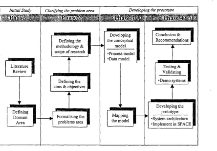
has been carried out. The general outline of the research methodology framework is
shown in Figure 1.1 where the research methodology has been divided into four phases.
The details of the work involved are as
follows:-1. Literature review has been conducted considering most of the previous research
done in the area under investigation. Information were collected from books,
journals, reports, conference proceedings, etc. Through this review, the domain area
is defined.
2. Once the domain area has been reviewed, the problem area is identified. In order to
achieve the aims and objectives of the study, the scope and the methodology of the
research need to be defined.
3. While developing the prototype model, the conceptual models for the domain area,
incorporating the multiple views of the integrated construction environment, are
developed. The structure framework for this environment is proposed by
representing the generic activities along with their relationships using the process
model. Later, the information required for the development of an integrated
construction environment is modelled in which it represents the building elements
data model. These models are then mapped into the project model in the
object-oriented environment.
Developing the prototype
Developing the conceptual
model
•Process model
•Data model
Testing & Validating
•Demo systems
[image:33.595.72.517.83.391.2]01 Developing the
I
prototypeFigure 1.1: Research methodology
•System architecture Implement in SPACE Defining the
methodology & scope of research
Conclusion & Recommendations
4. The prototype is developed and implemented into the SPACE environments. Two
steps have been taken, i.e. developing an object interpreter engine in the CAD
system and a building elements data model in an object-oriented environment. The
testing and validating of the prototype systems are done through a number of
demonstrations.
5. Finally, conclusions are drawn and the future developments of the research are
recommended.
Chapter I
1.7 Scope of the research
The main aims of this study is to establish a building elements data model which
support multiple designer views in order to serve all downstream construction
applications. The developed prototype system should incorporate most of the required
design information. However, the development and implementation stages of this work
are limited to the
following:-1. The design elements are limited to reinforced concrete office building.
2. The number of design elements interpreted is limited to cavity wall, solid wall,
window, door, beam, column, slab and pad footing only.
3. The building elements data model contains limited views. For example, a column
is viewed in terms of its shape not in terms of its design. The design views have
been implemented separately in other data modules.
4. The topological relationships are limited to three types only, i.e. supported by,
attached to and embedded in. This is due to the complexity of identifying the
topological relationships using "wire frame" based CAD systems.
5. The implementation of the prototype is limited by the software used, i.e.
AutoCADAECTM and KAPPA-PC.
6. The design information which are captured, transferred and manipulated to the
central core, served only the applications developed concurrently.
1.7 Guide to the thesis
This thesis has been divided into eleven Chapters. This Chapter has identified the
fragmentation issue of the construction industry and stressed the needs of a structured
framework of an integrated construction environment whereby all the design and
construction applications can be integrated. The remaining Chapters are organised as
follows:-Chapter 2 highlights the information flow involved in the construction process
which needs to be managed to ensure smooth communication between the participants
in the project life cycle. It also highlights that the application of IT in the construction
industry can be use very effective if it has the ability to exchange and share information
among the project participants.
Chapter 3 examines the issue of information sharing, the concept and the
implementation. The approaches to integration and the current attempts towards the
development of an integrated environment in construction and other industries are
highlighted.
Chapter 4 examines the issue of data exchange and the standards with special
reference to the construction industry. The development of international standards,
Chapter 1
STEP and the latest development of Industry Foundation Classes (IFCs) by the IAI is
investigated.
Chapter 5 discusses the product modelling within the integrated environment in
which the information modelling approaches have been explained. A brief description
of product models developed in an integrated environment such as RATAS, ICON,
ATLAS, GenCOM, COMBINE, OSCON and WHISPER are reviewed.
Chapter 6 proposes a strategic, but generic, framework for establishing an
integrated construction environment. The typical product model of the proposed
framework at various levels of abstractions whereby a full process analysis of the
various activities are required to successfully establish such an environment is
explained. The implementation of the ICE, i.e. SPACE has been described including its
components, i.e. CAPE, SPECIFICATION, CONPLAN, EVALUATOR, INTESITE
and CONVERT.
Chapter 7 discusses and highlights the issue and the development of data sharing in
an integrated construction environment using object definition. The problems with the
implementation of data models by separating the theoretical and implementation issues
are highlighted. The importance of clearly defined objects and their attributes are
addressed. The structured concept of object's life cycle, which aims at managing
information and its flow within the integrated environments is also proposed.
Chapter 8 describes the data models, which represent the information required for
the development of an integrated construction environment including the development
of the "building elements data module" using EXPRESS-G modelling technique. The
data models have been decomposed at various levels of abstractions. The relationship
between the "building elements data module" with other modules is discussed by
stressing the impact of the "building elements data module" in the development of
other modules in the ICE.
Chapter 9 describes the implementation of the prototype and how the conceptual
data model is mapped into the object-oriented environment. The development of the
prototype have been divided into three main parts i.e. the graphical interface, the CAD
system in the AutoCADAECTM and the knowledge-based object-oriented database in
KAPPA-PCTM.
Chapter 10 describes the evaluation of the developed prototype. A demonstration
presentation has been carried out to determine the system's performance, capabilities
and its limitations. The testing procedure and the results from integrating the prototype
with other applications are also discussed.
Chapter 11 presents the summary and conclusions of the research work together
with the recommendations for future work.
Chapter 2
Information Management and the
Project Life Cycle
2.1 Introduction
Construction is one of the most information dependent industry which obtains
information from detailed drawings, cost analysis sheets, budget reports, risk analysis
charts, contract documents, etc. [Tucker & Mohamed, 1996]. During project life cycle,
the amount of information generated and exchanged is enormous even for a small-size
construction project. Therefore, information management which can highly influence
cost, time and quality becomes an important issue. Many authors believe that
information management can have a significant impact on the success and profitability
of the entire industry [Atkin, 1990; Vanier et al, 1993; Fischer et al, 1993].
Information management has been accepted as an essential management discipline
industries spend over 0.5% of their turnover on information management [Atkin, 1990].
However, there is no comparable figure in the construction industry and it is clearly
still lags behind. The reason behind this is that the construction industry is made up of a
large number of very small organisations. For example in UK, there are approximately
200,000 companies [DETR, 1996a]. This therefore causes problem in tabulating the
data.
This chapter presents the project life cycle stages, highlighting the role of
professionals involved in the project life cycle. The issues of information management
over the project life cycle and the needs for and problems of managing the project
information in the wake of the information technology (IT) era are also discussed.
Finally, the process of improving the management of project information flow is
highlighted.
2.2 Project life cycles stages
Generally, a project (construction or otherwise) is a unique undertaking for
essentially a single purpose which is defined by scope, quality, time, and cost
objectives [Ahuja et al, 1994]. A project occurs over an identified period of time during
which a changing level of effort is required to complete each stage. A project has also
been defined as the process of working to achieve a goal [University of Minnesota,
1997]. During the process, projects pass through several distinct phases, which are
called the project life cycles. Meanwhile, in a construction project, a project life cycle
can be viewed as a project proceeding sequentially through five distinct stages starting
Stage Controlled Process
Conceptual >
>
Design Tender 1\7 >Occupation/
Maintenance
S.
Construction
S.
IInception >
RIBA plan of work
Feasibility> Outline >
S.
Chapter 2
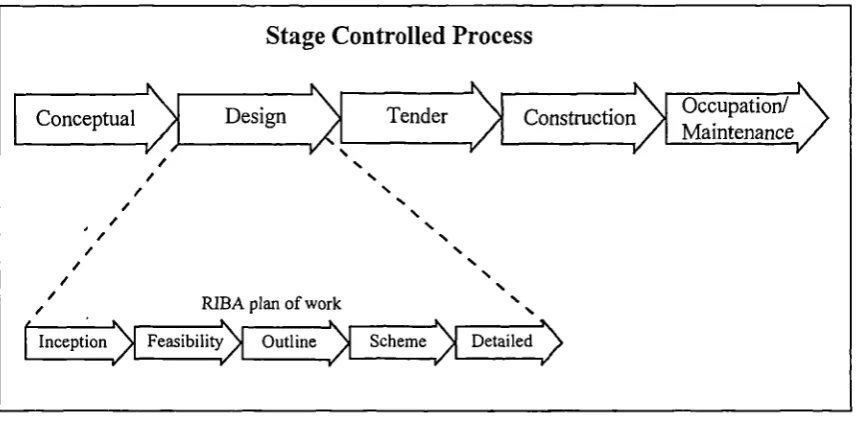
from the conceptual to the occupation/maintenance [Alshawi, 1996]. It includes
conceptual, design and tender as the pre-contract stages whereby the construction and
occupation/maintenance as the post-contract stages as shown in Figure 2.1.
In the traditional method of procurement, the pre-contract stage is the most
important stage in a project life cycle, whereby the contract is signed and tendered. It is
at this stage where decisions are made that can significantly affect the immediate and
long-term construction problems. The post-contract stage is the stage where a
contractor is appointed and the construction process is carried out. This is the stage
where all the documentation (bill of quantities and general arrangement drawings with
[image:40.595.65.498.397.612.2]detailed drawings and specifications) are supplied to the contractor.
Figure 2.1: Traditional project life cycle
The following sections briefly describe the five stages of the project life cycle
within the traditional procurement. It is outside of this study to explore such stages and
to examine the flow of the information between them.
2.2.1 Conceptual stage
The purpose of this stage is to establish the client's outline requirements, that is, to
decide what is required [Ward, 1979]. Such requirements are time/duration of the
project, cost of the project, construction reliability and performance and management.
The conceptual stage seeks to determine whether the project is capable of execution in
terms of its physical complexities, planning requirements and economics [Harvey &
Ashworth, 1993]. At this stage, the client must carefully investigate all alternative
sources before proceeding to the next stage.
2.2.2 Design stage
The design stage is a cyclical process with a linear progression, which in itself
comprises of several distinct phases [Alshawi, 1996]. Due to its nature, a guideline has
been proposed by the RIBA (Royal Institute of British Architects). This "RIBA plan of
work" (Figure 2.1) is a model procedure which provides a process for the design of any
project. It is not rigid and can be modified to meet the individual circumstances that
prevails on a particular project [Ward, 1979].
Initially, the design commences with the design brief, with the aim of establishing
the client's outline requirements. The client must make the decision to build, appoint an
architect, and consider the outline proposals for the project brief. The next stage is to do
a feasibility study, which aims at studying all technical, functional and financial aspects
associated with the project, and advising the client as to whether his proposal is
Chapter 2
feasible. If the client agrees to proceed with the project, the next stage will be the
outline proposals. The purpose of this stage is to examine alternative proposals in order
to determine the general approach to the layout, design and construction of the project
[Ward, 1979]. This process involves collaboration between the designers and the client.
During the scheme design stage, the wider issues of appearance, method of
construction, outline specification and financial matters are examined in detail. At the
end of this stage, the architect reviewing the evolving project design to date will
produce a report. This report is presented to the client for approval. Once the client has
approved the scheme, the design brief cannot be altered. The design of the scheme is
developed in depth in the detailed design stage. Final decisions are taken to facilitate
the full design of all parts and components of the building. At this stage, the designers
add low level of detail to the project's conceptual design, i.e. the project takes its final
form, such as detailed structural design, foundation design, services design, etc.
The'production information is the final stage of the design aiming to expand the
design information in order to give sufficient details for the project to proceed. The
production information includes production drawings, specifications, schedules,
contractual particulars and bill of quantities.
2.2.3 Tender stage
The purpose of tendering is to assign a contractor to carry out the construction of
the project [Ward, 1979]. During this stage, the construction documents are sent to the
appropriate contractor(s), depending upon the method of tender. Upon receipt of the
documents, the contractor estimates the costs to carry out the construction work and
adds an additional percentage for overheads and profit to arrive at a total tender figure
[Forster, 1986]. The contractor submits this figure as a bid for the work in competition
with other contractors. Traditionally, the contractor who submits the lowest bid is
awarded the contract. In addition, the bidding contractors must also submit a proposed
construction program (pre-tender program) to show the planned duration of the work
[Forster, 1986].
2.2.4 Construction stage
On being awarded a contract, the successful contractor, prior to taking possession
of the site, has to enlarge the pre-tender program and produce a long-term construction
plan. During site operations the contractor should carry out valuations of each
completed stage of work, whereupon interim certificates are prepared so that stage
payments may be made to the contractor and sub-contractor to pay for work done to
date. It is normal practice for a percentage to be retained to pay for faulty work, which
may develop or be subsequently discovered later.
Chapter 2
2.2.5 Occupation/Maintenance stage
Once the project has been completed and the work has been inspected and
approved by the designer (architect), the project is then handed-over to the client for
occupation. With the exception of a defects liability period (usually six months after the
hand-over date), where the contractor is responsible for rectifying any defected work,
the general maintenance and up-keep of the project now becomes the responsibility of
the client.
2.3 Procurement methods and the role of professionals
The professionals are individuals or organisations who are actively involved in the
project, or whose interests may be positively or negatively affected as a result of project
execution or successful project completion [PMI, 1996]. They may be clients, project
managers, designers (architects, structural engineers, building services engineers),
quantity surveyors, contractors, etc. The roles and responsibilities of professionals may
overlap because they often have very different objectives that may come into conflict.
For example, in the same project, an architect may be keen to look at only aesthetic
value, the structural engineers at the safety, the estimator at cost, etc.
The roles of professionals over the project life cycles rely on the co-ordination of
all parties involved in a project. This varies depending on the method of procurement
which normally implies a certain set of relationships between members of the design
team and other professionals [Brandon et al, 1988]. The procurement process is
undoubtedly the foundation on which perception of the construction industry and
therefore, the role of integration is based [Jennings & Kenley, 1996]. There are three
main methods of procurement currently being used in the construction industry, i.e.
traditional, design and build, and management. In the traditional method of
procurement, the client appoints independent consultants to act on his or her behalf to
produce the design and supervise the construction. Project delivery is viewed as a
sequential process in that the design is largely completed before the appointment of the
building contractor to whom detailed plans, specifications and possibly bill of
quantities must be given. In the design and build method of procurement, the client
makes an agreement with one single administrative entity (the prime contractor) who is
given responsibility for the whole project, from initial briefing and design through to
construction of the building. While in the management method of procurement, the
client appoints a management contractor to work alongside the other professional
consultants (thus combining the management and construction role). The aim of this
method is to incorporate construction expertise into the design at an early stage in the
project [Brandon eta!, 1988].
2.4 Integration problems
The traditional system of design and construction has led to a number of problems
for the industry [Ratcliffe, 1985]; (a) incomplete initial design caused changes in the
design during the process of construction and disruption to the building programme; (b)
the lack of clear detailed brief specifying the client's requirements at the outset creates
uncertainty and misunderstanding among the members of the professional team; and (e)
Chapter 2
failures to appoint consultants and contractors at early enough stage in the process and
distinguish clearly their roles and responsibilities, i.e. choosing the right method of
procurement systems, has led to ambiguity and lack of coherence.
This has led to a decay of integration between the various professions and to a
misunderstanding of the role of each profession. Several studies have outlined the
limitations of the traditional approach to the design and construction
process:-o The design process usually takes a considerable time depending on the size,
complexity and nature of the project [Alshawi, 1996];
o Design solutions do not usually meet budgetary constraints especially at early
design stages [Ferry & Brandon, 1991];
o Weak communication between members of the design team due to their different
design perspectives [Aouad eta!, 1994];
o Large percentage of construction problems on site are caused by complex designs
[Alshawi & Underwood, 1996];
At the design stage, each designer often works independently in a separate
location. Thus, the project team is only loosely integrated and this harms the efficiency
of the project. These problems are exacerbated by poor communications between the
project members and between the parent company and the project site [DETR, 1996b].
These poor communications affect the accuracy and efficiency of many of the stages of
the project life cycle, especially those concerned with the early life of the project. At
those stages, as explained earlier, better communications and the use of information can
produce large saving and could significantly impact the time and quality of the project.
2.5 Project co-ordination, the needs and benefits
In the traditional method of procurement, there are many parties involved directly
in a wide range of activities. One of these activities is the translation of the client brief
into design or from design into a constructed building. For example, during the
pre-tender stage, the architect, engineers, client and cost advisor share and exchange
information and data that evolves as the design progresses. At the early stage of project
life cycle, such co-ordinations are essential to ensure the success of the project.
Co-ordination is basically a management tool and can be defined as the bringing
into a proper relation of the various activities related to a project, or causing these
activities to function together, or in a proper order [Jegaraj, 1983]. While, the project
co-ordination is the planning of a project, or whole series of projects, well in advance
of the start of pre-contract work and the control of the project through all its stages
[NBA, 1972]. The main target of the project co-ordination is to provide a smooth flow
of information among the project's life cycle stages, i.e. by providing the means for
efficient communication [Vienna University of Technology, 1997]. Project
co-ordination also adds a new dimension to the project delivery strategy, i.e. the strategy
whereby each party involved must be co-ordinated towards a common goal, that is, the
timely delivery of an efficient project [Jegaraj, 1983].
Project co-ordination generally leads to an increase in efficiency, which can in turn
generates several benefits. A study by NBA (The National Building Agency) in the UK
[1972] revealed that such benefits are;
Drawings
Chapter 2
• Better communication, - improved appreciation of the work of each participants
involved;
o shorter construction time, - getting specifications, schedules and details to the
contractor at the right time;
o Earlier occupation, - earlier completion of the project.
Thus the project co-ordination is a necessary tool in the project delivery strategy
whereby the effectiveness of which depends on the creativity of the parties involved in
the project life cycle.
Project
Phase Feasibility Program ConceptualDesign DesignDetail ConstructionPlanning Construction Operatio
Report Drawings Data
Output
& Input
Sketches
Specifi-cations
Estimate Schedule
As-Built Drawings
Figure 2.2: Traditional fragmented and sequential project delivery process [Amended from Teicholz & Fischer, 1993]
Figure 2.2 shows the various phases of a project along with their inputs and outputs.
It can be clearly seen that the outcome of one phase is the input for the next. This
approach, which is usually materialised in the traditional procurement method,
enhances the industry fragmentation and makes the co-ordination process between the
different professionals difficult to achieve. Data is prone to errors because it is
extracted, transferred, interpreted, and repackaged very frequently. Therefore, it is
important to manage the flow of information in order to avoid or minimise the
problems.
2.6 Project information and information technology (IT)
Project information can be defined as the information that describes the physical
facility (product) and is required for managing its process [Australian STEP
Demonstration Project, 1995]. A typical set of project information may include site
survey, cost analysis, design drawings, specifications, regulations, bill of quantities,
project planning, job costing, estimates, valuations, material management, facility
management, etc. This information is usually handled by different departments within
one organisation or different organisations, resulting in long loops [Alshawi, 1996].
These loops can cause lengthy delays and inconsistencies of data used by different
departments.
Large amount of project information are generated and used during the various
stages of a project life cycle. Sharing and maintaining this information among multiple
disciplines and throughout a project's life cycle is a complex and difficult task [Ito et
al, 1990]. However, such flow of information needs to be managed so that it will be
received or accessed when required. Information management is not for handling
drawing issues only, but if it is correctly administered, it can provide the necessary
framework whereby everybody knows what his responsibilities are and how to carry
them out [Atkin, 1990].
In the era of the information age, information technology (IT) becomes a vital tool
for managing the information. IT is a generic term used to describe all types of
computer and communication technologies applied in the acquisition, storage and
Chapter 2
retrieval of information [Betts et al, 1989]. In the construction industry, it has been
proven that the use of IT could reduce the fragmentation problem [Betts et al, 1989;
Atkin, 1989]. Currently, however IT can only assist various processes in construction,
such as planning, estimating, structural design, etc., and does not automate them.
The large volume and diversity of information used and exchanged among
professionals with different backgrounds require the use of IT tools [Betts et al, 1989].
Current IT tools provide excellent means of transmitting the syntax of information, but
do not as yet have the capability to communicate the "meaning" of the information
which are supposed to be conveyed to other participants in the construction process.
The construction industry can benefit from the IT tools today through the facilities of
storage and manipulation of vast amount of data and their speedy transfer. Various
participants in the construction process use IT tools for specific functions in their
individual domains, but the information generated by the IT tools is not transmitted in a
directly useable form to other participants. However, many studies have suggested that
IT has the potential to be the most powerful tool for re-engineering the construction
process by improving the performance of traditional processes [Atkin, 1990; Tucker &
Mohamed, 1996; Tucker, 1996].
Despite the potential use of IT as a tool for managing the information flow, the
supply of information to the industry is still in poor condition. A recent study by DETR
(Department of Environment and Transport) UK [1996a] revealed that this problem
occurs due to the following;
o Information does not follow in a common format or description and is hard to find
and use;
o The source of information to the construction industry is fragmented and diverse;
o Information is often of unreliable quality and is not easily searchable or useable;
o Different access methods and user interfaces make it difficult to use a variety of
information sources;
The above statements is also supported by other construction organisations, which
also revealed that the underlying causes of the problems in the adoption and utilisation
of integrated IT systems, can be attributed to [Alshawi, 1996];
o poor management and communication;
o the fragmented nature of the industry;
o lack of standardisation and uniform procedures;
o the number of participants involved in construction projects;
The problems that the construction industry is facing today are obvious. The
process of managing the information flow in the construction process needs to be
improved in order to increase the productivity especially in terms of time and cost.
2.7 Managing the flow of information
As discussed earlier, the problem of managing the information is to bring the
participants to work and share the information together. The construction industry,
![Figure 3.5: Computer Integrated Construction [Amended from Goldscmidt &Navon, 1996]](https://thumb-us.123doks.com/thumbv2/123dok_us/8742061.889870/69.595.98.429.385.720/figure-computer-integrated-construction-amended-goldscmidt-navon.webp)
![Figure 3.6: Concurrent Engineering approach to the project life cycle[Amended from Alshawi, 1996]](https://thumb-us.123doks.com/thumbv2/123dok_us/8742061.889870/73.595.103.506.274.598/figure-concurrent-engineering-approach-project-cycle-amended-alshawi.webp)
![Figure 3.7: The traditional approach [Amended from Alshawi, 1996]](https://thumb-us.123doks.com/thumbv2/123dok_us/8742061.889870/74.595.70.508.175.391/figure-traditional-approach-amended-alshawi.webp)
![Figure 4.3: STEP Three-schema architecture [Yang, 1991]](https://thumb-us.123doks.com/thumbv2/123dok_us/8742061.889870/89.595.66.505.267.649/figure-step-three-schema-architecture-yang.webp)
![Figure 5.6: Relation between the different ATLAS models [Tolman & Poyet,1995]](https://thumb-us.123doks.com/thumbv2/123dok_us/8742061.889870/123.595.115.434.211.413/figure-relation-different-atlas-models-tolman-poyet.webp)
![Figure 5.7: A portion of the ATLAS LSE project type model [Tolman 1994]](https://thumb-us.123doks.com/thumbv2/123dok_us/8742061.889870/124.595.104.450.217.538/figure-portion-atlas-lse-project-type-model-tolman.webp)

