Blocky Artifacts Detection Algorithm for Compressed Digital Image
Suhaila Sari
a *,
Mohamad Affendi Nordin
b, Hazli Roslan
c,
Zarina Tukiran
d,
Siti
Zarina Mohd Muji
e,
Nan Mad Sahar
f,
Tasiransurini Ab Rahman
g EmbCos Research Group, Department of Computer Engineering,Faculty of Electrical and Electronic Engineering, Universiti Tun Hussein Onn Malaysia (UTHM),
86400 Parit Raja, Batu Pahat, Johor, Malaysia
a
suhailas @uthm.edu.my, b keypassleypass @gmail.com,
{ chazli, dzarin, eszarina, fnan,gsurini} @uthm.edu.my
Keywords: Image processing, Image compression, Blocky artifacts detection
Abstract. Image compression is a very important issue for many applications in the field of visual communications. The purpose of image compression is to reduce the storage and transmission costs while maintaining the image quality. Nowadays, image previewing on a mobile device is a practice that takes a great implementation of everyday live. However, the image compression with very low bit rates that is typically used on mobile platforms, usually may introduce visible compression artifacts, which is referred to blocky artifacts. This displaced blocky artifacts, although visually noticeable and annoying, is particularly difficult for automated detection because its location is a priori unknown, and its appearance might be easily mistaken for some real edges or fine details in the image. Therefore, the detection of the blocky artifacts is important to ensure the deblocking process is performed on the blocky artifacts only, not on real edges or fine details of the image. This paper proposes the development of a technique which aims in blocky artifacts detection for compressed digital image. The detection of blocky artifacts presented in this paper is performed in two parts that are vertical and horizontal detections utilizing proposed detection algorithms. The effectiveness of to detect the blocky artifacts detection without including the image edges and fine details is depending on the threshold value setting in the vertical and horizontal detections algorithms. After both detections are completed, then the last step is to combine both edgemaps into a new image which includes the blocky artifacts at the boundary between two different luminance gradients. The algorithm is developed in MATLAB software. The analysis for the result is made based on qualitative observation. For blocky artifacts detection, the proposed technique has achieved its objectives in detecting blocky artifact at the boundary between two different luminance gradients. Thresholding process separated the unwanted image fine details and edges, providing an output image a view of clearer blocky artifacts existing in the compressed image. It is also found that the proposed technique could detect blocky artifacts more effectively (without including image fine details and edges) in comparison to conventional techniques.
Introduction
Generally used methods in reducing blocky artifacts can be categorized into implementation in two domains. Based on previous researcher on image compression, techniques used [1]-[5] are implied either in spatial domain or frequency domain. In [2], 1D smoothing filter is used for complex regions, while 2D adaptive filtering is used in smooth regions. Most of the researches proposed iterative methods [6], where initially closed convex constraint sets are defined. Iterative computations of alternating projection onto these convex sets recover the original image from coded image. However, these methods usually have high computational complexity, thus are difficult to adapt to real time image processsing application.
In [7], G.A. Triantafylidis et.al proposed a novel frequency-domain technique for image blocky artifacts detection and reduction. This method detects regions of image which present visible blocky artifacts. This detection is performed in frequency domain and uses estimated relative quantization error calculated when the discrete cosine transform (DCT) coefficients are modeled by a Laplacian probability function. It is constrained by the quantization upper and lower bound.
The method in [8] introduced a novel and enhanced form of mean square of different slope (MSDS) in frequency domain which involves all neighbouring blocks, including diagonally located neighbouring blocks. A novel blockiness detection method which reduce the time and computational load of deblocking algorithm is proposed. This method has complex and long operation due to its high precision step.
I.O. Kirenko et.al [9] proposed a new method blocky artifacts reduction of MPEG compressed video sequences. The blocky artifacts reduction method can be applied in a system, where encoded bit-stream is not available. This method adapts filtering automatically based on a local spatial analysis and a block grid visibility. Thus, no external control parameters are required.
In [10], A. Gandam and J.S Sidhu proposed a new post-processing algorithm based on signal adaptive filtering along with corner outlier detection or replacement scheme. The proposed method uses signal adaptive filtering, corner outlier detection and replacement scheme. The 2-D median filter is used in filtering of smooth area. The algorithm reduces the blocky artifacts, such as grid noise, staircase noise and corner outlier, without degradation of image details.
In [11], K. Singh and P. Kumar attempt to further improvement on [12] by adding the concept of corner outlier detection and replacement algorithm. The corner outlier is visible at the corner point of 8 x 8 block at intermediate mode. In this mode, only pixels near the boundary are selected for the filtering window. Grayscale values are modified within the specified range around the grayscale values of neighbouring pixels. This method is simple and involves no change to wavelet transform.
With the use of existing blocky artifacts detection methods, some amount of blocky artifacts can be detected but at the same time some edges and fine details of image are included in detected edgemap. Therefore, a development of detection method which can balance the trade-off between blocky artifacts detection and without mistakenly including edges and fine details is still required. The main objective is to design a detection algorithm for blocky artifacts at the block border in compressed digital image. The results of detected blocky artifacts are analyzed and the performance of proposed method is compared to conventional detection methods. The proposed method is developed by using MATLAB software and simulated for digital natural images.
Proposed Detection Method
The flow of this method can be divided into 3 parts: vertical detection, horizontal detection and combination of both vertical detection and horizontal detection to form the final edgemap image.
Vertical Detection
Pixel continuity is tested by calculating luminance gradient values that act as low pass filter so that small detail is not mistaken as pixel discontinuity. This is the most important part to separate edges and blocky artifacts in proposed method. Two variables are calculated :
A (i,j) = [ f (x,y) – f (x,y + 1) ] – [ f (x,y – 1) – f (x,y) ] (1)
A(i,j) and B(i,j) are discontinuity vertical luminance repectively. A(i,j) and B(i,j) are checked
the boundary between f(x,y) and f( vertical detection, g(i,j) is generated
.gi,j= 255 0
Horizontal Detection
Next the horizontal detection is performed i
C (i,j) = [ f (x,y)–
D (i,j) = [ f (x,y) –
Both variables are checked based on threshold value
between f(x,y) and f(x,y+1) is considered as pixel discontinuity.
horizontal detection h(i,j) is generated based on
.hi,j= 255 0
Combination Detection
After vertical and horizontal detection are completed, both examined again for every pixel location
is referred to the last edgemap image produced denoted as
.k (i,j)=
Result And Discussion
For comparison purposes, proposed method is database. For simplicity, results for
discussion purpose. The image is partially
blocks division to investigate the effectiveness of proposed method to differentiate b with real edges or details. The performance
evaluation method, which is visual
compared with conventional detection methods
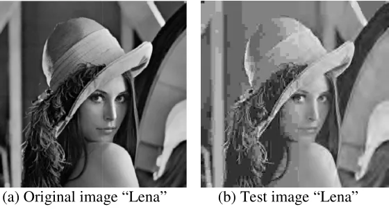
[image:3.612.167.447.570.721.2](a) Original image “Lena”
Fig. 1 : Utilized
are discontinuity vertical luminance gradients at pixel location (
are checked based on threshold value, Th. If the condition is met, then
(x,y+1) is considered as pixel discontinuity. Then
generated based on:
255 if (A(i,j) ≥Th) and B(i,j) ≥ Th)
0 if (A(i,j) < Th) and (B(i,j) < Th)
is performed in horizontal direction:
– f (x + 1,y) ] – [ f (x –1,y) – f (x,y) ]
– f (x + 1,y) ] – [ f (x + 1,y) – f (x –2,y) ]
checked based on threshold value, Th. If the condition is met, the boundary
+1) is considered as pixel discontinuity. The new edgemap generated based on:
255 if (C (i,j) ≥ Th) and (D(i,j) ≥ Th)
0 if (C(i,j) < Th) and (D(i,j) < Th)
After vertical and horizontal detection are completed, both g(i,j) and h(i,j) edgemaps
again for every pixel locations to be combined for final image. The final image generated
is referred to the last edgemap image produced denoted as k(i,j).
)= 255 if g (i,j) = 255 or h (i,j) = 255
0 otherwise
proposed method is tested by using natural images from the SIDBA for “Lena” image with the size of 256 x 256 is shown
partially compressed using DCT compression of effectiveness of proposed method to differentiate b
performance is evaluated by using subjective image quality effects comparison of restored images. Proposed method is detection methods such as zerocross detector and Prewitt detector
image “Lena” (b) Test image “Lena” Utilized image for proposed method analysis
(x,y) and (x,y+1) condition is met, then is considered as pixel discontinuity. Then edgemap of
(3)
(4)
(5)
condition is met, the boundary edgemap image of
(6)
) edgemaps generated are The final image generated
(7)
from the SIDBA size of 256 x 256 is shown for using DCT compression of 8-by-8 sub-effectiveness of proposed method to differentiate blocky artifacts
Vertical, Horizontal and Combination Detections’ Edgemap Results
For test image “Lena” shown in Fig. in Fig. 2, if the threshold values is equal to
the proposed method. However, we can observed that
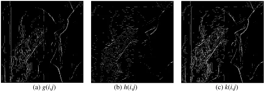
(a) g(i,j)
Fig. 2: Proposed method edgemap
detection edgemap, h(i,j), (c) Combination of vertical and horizontal
Optimum Threshold Value Setting
Optimal threshold value settings,
suitable threshold value is crucial for preventing edgemaps. Threshold values are investigate
Fig. 3 illustrates the final edgemap k
[image:4.612.92.527.130.280.2](a) Th= 10
Fig. 3: Final edgemap
It can be observed that when the threshold value is low, in the resulting edgemap. On the other hand, larger dissappear but the blocky artifacts are
suitable threshold value for this m artifacts while discarding unwanted edges.
Blocky artifacts are preserved due to the calculation were made in (1),
B(i,j) are used for vertical detection and
calculation is simply manipulates the values of pixel pixels. The difference intensities will dete
construct new edgemap image. Low luminance gradient show and high luminance gradient will represent blocky artifacts. gradient is higher than threshold value, blocky artifact
Detection Methods Comparison
The zerocross detector and Prewitt detector are performed t
Vertical, Horizontal and Combination Detections’ Edgemap Results
“Lena” shown in Fig. 1, the threshold value settings is 5. From resulting edgemap equal to 5, both blocky artifacts and strong edges are detected by the proposed method. However, we can observed that fine details has been excluded succesfully.
(b) h(i,j) (c)
edgemap result: (a) Vertical detection edgemap, g(i,j)
), (c) Combination of vertical and horizontal detection edgemap,
Optimum Threshold Value Setting
, Th is fixed as follows for implementation in practice.
is crucial for preventing mistakenly including real edges into
ues are investigated ranging from 5 to 30. For convenient comparison,
k(i,j) images by using Th ranges = 10, 20 and 30
(b) Th= 20 (c)
inal edgemap k(i,j) images by using different Th ranges
It can be observed that when the threshold value is low, blocky artifacts and strong edges On the other hand, larger threshold values caused the
s are affected as well. From observation made to
suitable threshold value for this method is Th = 20 because the image still preserved blocky
while discarding unwanted edges.
preserved due to the calculation were made in (1), (2), (4) and (5).
) are used for vertical detection and C(i,j) and D(i,j) for horozontal detection, respectively. The
calculation is simply manipulates the values of pixel intensity and compared it with neighbouring . The difference intensities will determine the luminance gradient that later will be used to construct new edgemap image. Low luminance gradient shows that it includes mostly image edges
gradient will represent blocky artifacts. Therefore, if the value of gradient is higher than threshold value, blocky artifacts will be preserved.
n
The zerocross detector and Prewitt detector are performed to compare the performance of proposed From resulting edgemap , both blocky artifacts and strong edges are detected by
excluded succesfully.
(c) k(i,j)
), (b) Horizontal detection edgemap, k(i,j)
fixed as follows for implementation in practice. Selecting mistakenly including real edges into resulting 0. For convenient comparison,
0, respectively.
(c) Th= 30
blocky artifacts and strong edges appear the image edges to to the images, the 0 because the image still preserved blocky
(4) and (5). A(i,j) and ) for horozontal detection, respectively. The intensity and compared it with neighbouring mine the luminance gradient that later will be used to mostly image edges the value of luminance
[image:4.612.89.528.393.549.2]
method with conventioned methods for blocky artifacts detection in compressed image methods are implemented in MATLAB and
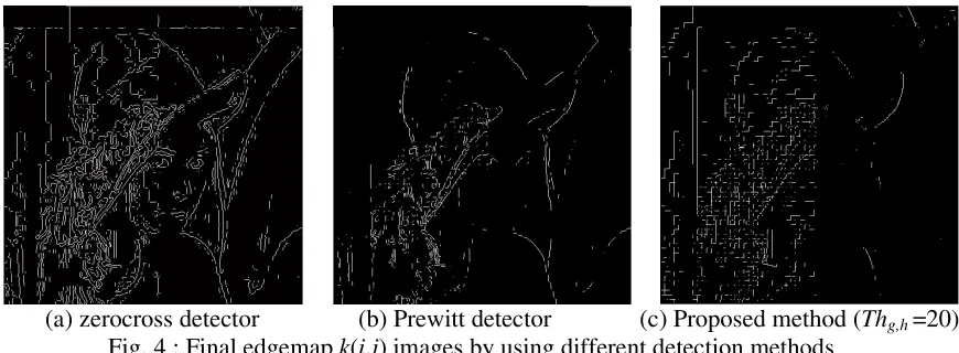
[image:5.612.92.527.103.263.2](a) zerocross detector
Fig. 4 : Final edgemap
For blocky artifacts detection, it is found that the proposed method could detect blocky artifacts more effectively (without include image edges) in comparison to conventional methods.
Conclusion
Though simulation results, the proposed method
artifacts at the boundary between two different luminance gradient important role to ensure blocky artifacts in an image
image details and edges. For further work, quantitative
verify the results obtained since current results analysis is based on qualitative observation.
References
[1] H. Reeve, J. Lim, Reduction of blocking effect in image coding, I and Signal Processing (1983)
1212-[2] Y.F. Hsu, Y.C. Chen, A new adaptive separable median filter for removing blocking effects, IEEE Trans. Circuits Systems and Video Technology
[3] T. Meier, K. N. Ngan, G. Crebbin, degraded by blocking effects, IEEE Tencon
[4] W. C. Zhang, W. J. Fang, X.Z, Adaptive reduction of blocking artifacts in DCT domain compressed images, IEEE Trans. Consumer Electronics, vol. 50, pp. 647
[5] G. Lakhani and N. Zhong, Derivation of prediction equations for blocking effect reduction, IEEE Trans. Circuits Systems and Video Technology 9
[6] S. Minami, A. Zakhor, An optimization
coding, IEEE Trans. Circuits Systems and Video Technology [7] G. A. Triantafyllidis, D. Tzovaras
compresse data, IEEE Trans. Circuits Systems and Video Technology [8] I. O. Kirenko, R. Muijis, L. Shao,
vision measure, IEEE Transactions on Circuits Systems and Video Technology
[9] I. O. Kirenko, R. Muijs, L. Shao, New method for the reduction of artifacts in MPEG compressed video sequences, IEEE Multimedia
[10] A. Gandam, J. S. Sidhu, A post outlier, Int. J. Computer Applications
[11] K. Singh, P. Kumar,Algorithm for blocking artifact detection and reduction using adaptive filtering in compressed image, Int. J
[12] S. Singh, V. Kumar, H. K. Verma, Images, Digital Signal Processing 17
with conventioned methods for blocky artifacts detection in compressed image methods are implemented in MATLAB and utilizing default parameter settings.
(b) Prewitt detector (c) Proposed method (
inal edgemap k(i,j) images by using different detection methods
blocky artifacts detection, it is found that the proposed method could detect blocky artifacts more effectively (without include image edges) in comparison to conventional methods.
he proposed method has achieved its objectives in detecting blocky at the boundary between two different luminance gradients. Thresholding
blocky artifacts in an image are detected correctly without including er work, quantitative analysis also must be performed
since current results analysis is based on qualitative observation.
J. Lim, Reduction of blocking effect in image coding, Int. Conf. Acoustics, Speech, -1215.
Y.C. Chen, A new adaptive separable median filter for removing blocking effects, Circuits Systems and Video Technology (1993) 510-513.
Crebbin, A region-based algorithm for enhancement of images IEEE Tencon1 (1996) 405-408.
Fang, X.Z, Adaptive reduction of blocking artifacts in DCT domain Consumer Electronics, vol. 50, pp. 647-654, 2004.
G. Lakhani and N. Zhong, Derivation of prediction equations for blocking effect reduction, Circuits Systems and Video Technology 9(1999) 415-418.
A. Zakhor, An optimization approach for removing blocking effects in transform Circuits Systems and Video Technology 5(1995) 74–82.
A. Triantafyllidis, D. Tzovaras, M. G. Strintzis, Blocking artifact detection and reduction in Circuits Systems and Video Technology 12(10)(2002)
Shao, Coding artifact reduction using non-reference block grid IEEE Transactions on Circuits Systems and Video Technology(2006)
I. O. Kirenko, R. Muijs, L. Shao, New method for the reduction of artifacts in MPEG compressed video sequences, IEEE Multimedia and Expo7(1)(2006) 469-472.
A post-processing algorithm for detection and removal of corner
Computer Applications, 4(2)(2010).
P. Kumar,Algorithm for blocking artifact detection and reduction using adaptive
J. Computer Applications4(2)(2010)
K. Verma, Reduction of blocking Artifacts in JPEG compressed Digital Signal Processing 17(2007) 225-243.
with conventioned methods for blocky artifacts detection in compressed image. Both
(c) Proposed method (Thg,h =20)
t detection methods
blocky artifacts detection, it is found that the proposed method could detect blocky artifacts more effectively (without include image edges) in comparison to conventional methods.
its objectives in detecting blocky . Thresholding setting plays an without including real performed in order to since current results analysis is based on qualitative observation.
Acoustics, Speech,
Y.C. Chen, A new adaptive separable median filter for removing blocking effects,
based algorithm for enhancement of images
Fang, X.Z, Adaptive reduction of blocking artifacts in DCT domain 654, 2004.
G. Lakhani and N. Zhong, Derivation of prediction equations for blocking effect reduction,
ng effects in transform
G. Strintzis, Blocking artifact detection and reduction in (10)(2002) 877-890.
reference block grid (2006) 469-472. I. O. Kirenko, R. Muijs, L. Shao, New method for the reduction of artifacts in MPEG
processing algorithm for detection and removal of corner
P. Kumar,Algorithm for blocking artifact detection and reduction using adaptive