International Journal of Emerging Technology and Advanced Engineering
Website: www.ijetae.com (
ISSN 2250-2459,
ISO 9001:2008 Certified Journal,
Volume 3, Issue 3, March 2013)
555
Productivity Improvement Of Internal Ball Track Cutting
Process Of Hydraulic Steering Gear Nut
.Kotkar D.R.1, Wakchaure V. D.2
1
Mechanical Department (Design), Amrutvahini College of Engineering, Pune University, Pune, India. 2Assistant Professor, Mechanical Department, Amrutvahini College of Engineering, Pune University, Pune, India.
Abstract— Productivity improvement has been a significant
point of focus in industries as it drastically increases the bottom line. Industries invest considerably in their manufacturing process equipment to increase tool life, decrease process cycle times and increase productivity. In this paper we present our work on design and development of a new special purpose machining tool for cutting of internal ball tracks of a hydraulic steering gear nut. Our work was inspired by the need for increase in productivity and was sponsored by ZF Steering Gear (India) Ltd. By employing the aforementioned tool we were successfully able to increase the throughput by 67.43% (i.e. 236 parts/day).
Keywords— Productivity, Cycle time, Internal ball cutting process.
I. INTRODUCTION
Ball track cutting has been widely used in industries for manufacture of recalculating ball screw and nut. The process resembles thread cutting but is done with a special tool which is semicircular in shape, machining ball track externally is comparatively simple while internal track machining demand higher tool rigidity owing to a restricted machining space and vibration caused due to tool overhang. These constrains consequently affect the machine cycle time, decreases the throughout.
Our work summarized in this paper, thus an effort to increase the throughput of internal ball track cutting process of hydraulic gear nut, due to higher machining cycle times the throughput of our client firm (ZF Steering India Ltd) was 520 parts per day limited to 350 part per day. The tool demand of gear nut exceeded the current manufacturing capacity. The only feasible solution for this was to decreases the machine time considerably by designing dedicated tool.
The tool was designed two cutting point with distance equal to pitch of the ball track. and offset of 0.12 mm was given to distribute the machining load as a result the number of passes required for machining reduced by 33.33% (i.e. from 45 to 30 ).An overall decrease of 74 sec in cycle time was achieved with the increased throughput reaching 586 part per day.
II. PROBLEM STATEMENT CONSIDERING PRODUCTIVITY.
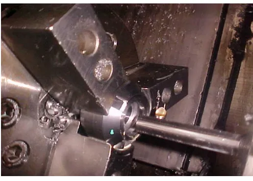
[image:1.612.323.581.274.459.2]The MKU-8 m/c is used for internal thread cutting of steering gear nut.
Fig. 1. Process of internal thread cutting
In whole day internal thread cutting of steering nut by adding the various allowances the time available with us is 19.55 hrs (1173 min).
Table 1 Daily Production Details.
Shift’s detail Requirement of steering nut/day
M/C manufactures nut/day
1st shift 180 120
2nd shift 180 120
3rd shift 160 110
Total jobs manufacture in whole day is 350.
Therefore, Requirement of steering nut/day –Actually M/C manufactures nut/day
International Journal of Emerging Technology and Advanced Engineering
Website: www.ijetae.com (
ISSN 2250-2459,
ISO 9001:2008 Certified Journal,
Volume 3, Issue 3, March 2013)
556
Hence, 170 more jobs are required to achieve the daily production target.III. DATA COLLECTION
[image:2.612.318.570.140.302.2]Previous Working Condition:-
Fig. 2 Previous Tool & Tool-holder.
This is previous working condition, in this single tool & tool holder is used for internal ball track cutting of steering gear nut.
For Tool HSS (High Speed Steel) material is used. Specification of HSS:
C % - 0.65 to 0.80 Mn % - 0.1 to 0.4 Si % - 0.2 to 0.4 Cr % -3.75 to 4 W % - 17.25 to 18.75 V % - 0.9 to 1.3
For Tool holder 16MnCr5 material is used. Specification of 16MnCr5:
C % - 0.12 to 0.20 Mn % - 1.3 to 1.7 Si % -0.1 to 0.35 Cr % - 0.5 to 0.8 Observation Table:-
Rpm- 300 rpm Feed- 14 mm/rev No. Of Passes- 55
[image:2.612.50.288.175.359.2](1) Reading taking time - 10.30 am
Table 2 Previous Cycle Time.
Sr.
No
.
J
o
b
lo
a
din
g
time (
sec
)
M
/c
s
ta
rt
t
ime
(s
ec
)
O
pera
tio
n
st
a
rt
time (
sec
)
M
/c
s
to
p
time
(s
ec
)
M
/c
s
to
p
time
(s
ec
)
J
o
b
un
lo
a
din
g
time (
sec
)
T
o
ta
l
time
(min
.)
1 3.95 3.28 4.86 1.98 1.98 3.25 3.04 2 2.44 3.27 4.52 2.09 2.09 3.25 3.02 3 4.25 3.26 4.59 2.22 2.22 3.44 3.05 4 4.39 2.35 4.86 2.26 2.26 3.30 3.06 5 5.2 3.19 5.00 2.19 2.19 3.39 3.06
Average time required for complete 1 job is 3.04 min.
IV. OPTIONS TO IMPROVE PRODUCTIVITY OF INTERNAL
THREAD CUTTING PROCESS
Two Components and Two Tool At A Time:-
Arrangement for this process is as shown in fig. i.e. spacer is placed between two components for adjusting the pitch distance of steering gear nut. There are two cutting tools on the tool holder, so that they create ball track on two nuts respectively. Arrangement for this process is as shown in fig. i.e spacer is placed between two components for adjusting the pitch distance of steering gear nut. There are two cutting tools on the tool holder, so that they create ball track on two nuts respectively.
[image:2.612.351.549.503.623.2]International Journal of Emerging Technology and Advanced Engineering
Website: www.ijetae.com (
ISSN 2250-2459,
ISO 9001:2008 Certified Journal,
Volume 3, Issue 3, March 2013)
[image:3.612.49.287.138.300.2]557
Fig. 4 Two Components And Two Tool.
One Component and Two Tool At a Time:-
In this arrangement there are two bits creating ball track on single nut.
Fig. 5 Modified Tool with Tool-holder.
[image:3.612.317.571.188.523.2]V. DIFFERERENCE
Table 3
Difference between One Component & two component with modified tool.
Parameter One component
modified tool
Two component modified tool
Overhang of tool holder
100 mm 131 mm
Changes Tool & tool holder modification
jaw , spacer , tool holder
modification
Loading time 10 sec 30 sec
No. of passes 23 45
Time per pass 4 sec 3.8 sec
M/C cycle time 100 sec 178 sec
No. of component / cycle
1 2
Floor to floor time/compo.
110 sec 104 sec
Overhang of tool holder
100 mm 131 mm
Quality More Less
Considering this table, one component modified tool have more advantages over the two component modified tool.
Since quality is the main issue of rejecting the two components modified tool.
[image:3.612.62.272.369.498.2]International Journal of Emerging Technology and Advanced Engineering
Website: www.ijetae.com (
ISSN 2250-2459,
ISO 9001:2008 Certified Journal,
Volume 3, Issue 3, March 2013)
558
VI. DESIGN FOR ONE COMPONENT MODIFIED TOOL.
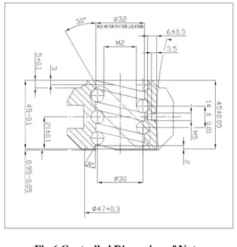
[image:4.612.329.558.141.329.2]Controlled Dimension of Nut:-
Fig.6 Controlled Dimension of Nut.
Central ball track from the reference face is given by mm.
Ball track pitch is mm.
Internal diameter of hydraulic steering gear nut is 32 mm
Controlled Dimension of Tool:-
Pitch of the tool is limited to mm
Offset distance between two cutting point of tool
is 0.12mm
Helix angle of tool is
Shank diameter of the tool is given by 8mm
Pitch of the tool is limited to mm
Offset distance between two cutting point of tool
is 0.12mm
Helix angle of tool is .
Shank diameter of the tool is given by 8mm
Fig. 7 Controlled Dimension of Tool
High speed steel (HSS or HS) is a subset of tool steels, usually used in tool bits and cutting tools. It is often used in power saw blades and drill bits. It is superior to the older high carbon steel tools used extensively through the 1940s in that it can withstand higher temperatures without losing its temper (hardness). This property allows HSS to cut faster than high carbon steel, hence the name high speed steel. At room temperature, in their generally recommended heat treatment, HSS grades generally display high hardness (above HRC60) and a high abrasion resistance (generally linked to tungsten content often used in HSS) compared to common carbon and tool steels
Alloying compositions of common high speed steel grades (by %wt)
Grade C Cr Mo W V Co Mn Si
T1 0.65–
0.80
3.75– 4.00 -
17.25– 18.75
0.9– 1.3 -
0.1– 0.4
[image:4.612.83.256.179.359.2]International Journal of Emerging Technology and Advanced Engineering
Website: www.ijetae.com (
ISSN 2250-2459,
ISO 9001:2008 Certified Journal,
Volume 3, Issue 3, March 2013)
559
Fig.8. Modified Tool
VII. DESING OF TOOL HOLDER
The spindle power = 9 kw
Nut internal dia. = 32 mm r = 16mm
• Speed N = 400 a) Velocity Calculation:-
Linear velocity will be,
Velocity = radius angular velocity V = r w
V =
= (16 2 400) / 60 = 16 41.89
V =670.206 mm/ sec b) Force calculation -
Power = force velocity Force =
F =
= F = 13.43 kN c) Torque Calculation:-
Power = angular velocity Torque P = T
P = T =
T = 214.85 N-m
d) Diameter Calculation:-
From Torsional formulae,
Where,
T = Torque or twisting moment J = Polar moment of inertia = Ixx+ IYY
=
G = Modulus of rigidity = Angle of twist (permissible)
The permissible torsional deflection „ ‟ depends upon the application and varies from about 0.3 degree/meter for machine tool spindles to about to 3 degree /meter for line shafting.
Permissible angle of twist is .
And, for 20MnCr5 modulus of rigidity is 80 Pa.
d d d 22 mm
For safety we take diameter of tool holder e) Design of Tool holder for Lateral Rigidity:-
For, tool holder material the modulus of elasticity is given by E= 103 GPa & permissible deflection at the support OR fixed end is given by ,
mm
Now maximum deflection at fixed OR support end of cantilever beam is given by,
Where, E=Modulus of elasticity I=moment of inertia
=
International Journal of Emerging Technology and Advanced Engineering
Website: www.ijetae.com (
ISSN 2250-2459,
ISO 9001:2008 Certified Journal,
Volume 3, Issue 3, March 2013)
560
=
=
d = 0.02176 m d = 21.761mm d
Now, Max. Bending moment & shear force acting on tool holder.
For design purpose we consider the tool holder as cantilever beam & cutting force is acting at the free end only.
f) Calculation of Shear Force:-
For that, calculate support reaction. 13.43 kN
27
Fig.9. Loading Diagram. ∑ RA+13.43=0
RA=13.43 kN
Shear force at various points, s.f @ left of A = 0
s.f @ right of A=13.43 kN s.f @ left of B=13.43 kN s.f @ right of B=0
13.43kN 13.43kN
A B
Fig.10. Shear force diagram.
Now, bending moment diagram Bending moment calculation,
Bending mmt @ A = +1181.84 kN-mm Bending mmt @ B = 0 .
88 27 A B
1181.84 kN-mm
Fig.11. Bending moment diagram.
Hence, from calculation max. Bending moment is 1181.84 kN.
Now, from properties of 2oMnCr 5
The allowable torsional moment = 250 N-m. The allowable bending moment = 1250 N-m.
Hence, the shear force and bending moment is within the permissible limit.
Drawing of Tool holder:-
Fig.12. Tool holder Drawing Sheet.
B
A
International Journal of Emerging Technology and Advanced Engineering
Website: www.ijetae.com (
ISSN 2250-2459,
ISO 9001:2008 Certified Journal,
Volume 3, Issue 3, March 2013)
[image:7.612.46.293.370.637.2]561
VIII. CYCLE TIME AFTER INSTALLATIONTable 4 New Cycle Time.
Average time required for complete 1 job is 1.59 min.
IX. COMPARISON OF PREVIOUS WITH INSTALLED
Parameter Previous tool and tool holder
Modified tool and tool holder Changes --- Tool and tool
holder modified Loading and
unloading time
10 sec 10 sec
No.of passes 45 30
Time/pass(sec) 3.80/pass 4 (sec) M/C cycle time 178 sec 104 sec
No. of
component/ cycle
1 1
Floor to floor time/job
188 sec 116 sec
Overhang of tool holder
85 mm 100
X. CONCLUSION
1) After installation by reducing the cycle time productivity of MKC-8 CNC machine is increased. 2) Requirement of steering gear Nut=520/day. 3) Machine manufacture after installation=586/day.
REFERENCES
[1 ] “Metal cutting machine tool‟s” by G.Thirupati Reddy, 3rd edition.v,
pp. 1-15.
[2 ] “Metal cutting machine tool‟s” by G.Thirupati Reddy, 3rd edition,
pp. 25-45.
[3 ] “Production Technology” by Anup goal, 1st edition, 2009,
pp110-110.
[4 ] “Dessign Of machine element‟s” by R. B. Patil, edition 2008, pp.
176.
[5 ] “Strength of material” by R. B. Patil, edition 2007, pp. 345-376.
[6 ] “Industrial management & engineering” by A. K. Bewoor, pp.
50-26.
[7 ] “Design data book of engineering”, pp. 67-128.
[8 ] D. Zhang, D. Chen, Optimization of cutting parameters in
vibration tapping of titanium alloys, Acta Aeronautica et Astronautica Sinica 13 (10) (1992).PP (B571-B573), pp. 6-8.
[9 ] Phelan R. M., fundamental of Mechanical Design, Tata
McGraw-Hill, 1975,pp. 2-6.
[10 ]Reshetov D.n., machine Design,MIR Publishar, 1965, pp. 4-7.
[11 ]L. Seaman, D.R. Curran, D.A. Shockey, Scaling of shear ban
fracture processes, in: J. Mescall, W. Weiss (Eds.), Material Behavior Under High Stress and Ultrahigh Loading Rates, Plenum Press, New York, 1983. PP (295-307).
[12 ]Spotts M.F., Machanical Desine Analysis, Prenttice, 2002, pp.
24-54.
[13 ]Y. Suzuki, S. Kamo, M. Uno, Study on machining by the use of
ultrasonic screw vibration (5th report) ultrasonic vibration tapping for natural rubber, JSPE 60 (1) (1994), PP . 148-152.
S r. N o . J o b lo a d in g ti me ( se c) M /c st a rt ti me ( se c) Op er a ti o n st a rt ti m e (sec ) Op er a ti o n ti me ( se c) M /c st o p ti me ( se c) J o b u n lo a d in g ti me ( se c) T o ta l ti m e (sec )
1. 3.95 3.28 4.86 104.15 1.98 3.25 119.37
2. 2.44 3.27 4.52 103.89 2.09 3.25 118.87
3. 4.25 3.26 4.59 105 2.22 3.44 120.61
4. 4.39 2.35 4.86 104.50 2.26 3.30 119.66