DESIGN AND IMPLEMENTATION OF MULTIPLE USER MOBILE ROBOT FOLLOWING SYSTEM
ZAHARI BIN HASAN
A project report submitted in partial fulfilment of the requirement for the award of the
Master of Electrical Engineering
Faculty of Electrical and Electronic Engineering Universiti Tun Hussein Onn Malaysia
ABSTRACT
Recently automation product for intelligent robot is increasingly getting very common. By the help of intelligent robot technologies that increased comfort, greater safety and security, life has been becoming easier [1]. With this system, mobile robot can be controlled from any target. It is desirable in many applications for a mobile robot to track and follow a person. The purpose of this thesis is to detail the design and implementation of a mobile robot following system through the use of beacons and remote control encoder decoder. This project entailed the design and construction of a mobile robot with the capability of determining its location in reference to know reference points and correct address. The implementation involved the use of ultrasound to determine the distance between the robot and known reference points and infrared decoder and decoder to determine the correct leader. From the distance, the Cartesian coordinates for the robot’s location along the horizontal plane where determined.
ABSTRAK
Pada masa ini produk automasi untuk robot pintar semakin mendapat sambutan. Dengan bantuan teknologi robot pintar yang dapat meningkatkan keselesaan, keselamatan dan keselamatan , kehidupan telah menjadi lebih mudah [1]. Dengan sistem ini, robot mudah alih dapat dikawal dari mana-mana sasaran. Ia adalah wajar kerana dalam banyak aplikasi, robot mudah alih dapat mengesan dan mengikuti seseorang. Tujuan tesis ini adalah untuk menerangkan dengan lebih jelas tentang reka bentuk dan pelaksanaan sistem ikutan robot mudah alih dengan menggunakan ‘beacon’ dan pengkod serta penyahkod kawalan jauh. Projek ini melibatkan reka
CONTENTS
CHAPTER CONTENTS PAGE NO.
TITLE i
STUDENT DECLARATION ii
ACKNOWLEDGEMENT iii
ABSTRACT iv
ABSTRAK v
CONTENTS vi
LIST OF TABLES xi
LIST OF FIGURES xii
LIST OF SYMBOL AND ABBREVIATIONS xvi
LIST OF APPENDICES xviii
CHAPTER 1 INTRODUCTION
1.1 Project Overview 1
1.2 Introduction 2
1.3 Problem Statement 3
1.4 Objective 4
1.5 Scope of Work 4
CHAPTER 2 LITERATURE REVIEW
2.1 Background of the chapter 7
2.2 Literature related to area of study 8 2.2.1 Sensor Based Approach 8 2.2.2. Transmitter and receiver Based 8
Approach
2.2.3 Following System Using Infrared based 9 Approach
2.2.4 Following System Using Blinking LED 10 Devices
2.2.5. Following System Using an Ultrasonic 11 Positioning System
2.2.6 Following System using Intelligent Space 11 Approach
2.2.7 Following Systems Using 12 Combined/Multi-Mode Approach
2.2.8 Microcontroller 12
2.2.9 Gps 14
2.2.9.1 Position Solution 15 2.2.9.2 Accuracy and Update Rate 15 2.2.10 Beacon Based Positioning System 16
CHAPTER 3 METHODOLOGY
3.1 Background 18
3.2 Ultrasonic, encoder and detector 19 3.2.1 Ultrasonic principle 19
3.2.2 Encoder design 22
3.2.3 Decoder design 22
3.5 Detection Circuit 27
3.6 Positioning System 28
3.7 Algorithm 32
3.7.1 Triangulation and Trialation 34
3.8 IFC (Interface Free Controller). 35
3.8.1 IFC-MB00 (Main Board) 36
3.8.2 IFC-PC00 (Power Card) 37
3.8.3 IFC-CP04 (Control Panel Card) 38
3.8.3 (a) Communication Address 38
3.8.4 IFC-BL002(Brushless Motor Card) 39
3.8.5 IFC-DI08 (Digital Input Card) 39
3.8.6 IFC-AI08 (Analogl Input Card) 40
3.9 Brushless DC Motor 41
3.10 Block Diagram 42
3.11 MPLAB® C Compiler for PIC18 MCUs (C18) 42 3.12 MPLAB® X Integrated Development 43
Environment (IDE)
3.13 Basic Control System Concepts 44
3.13.1 The open loop system 44
3.13.2 The closed loop system 45
3.13.3 On/Off Controller 45
3.13.4.1 The proportional term 48
3.13.4.2 The integral term 49
3.13.4.3 The derivative term 50
3.13.4.4 PID Control Loop Tuning 51
3.14 Software Implementation 51
3.14.1 Leader and the Follower Robot interaction 51 3.14.2 Software Implementation for the Follower 52 Robot
CHAPTER 4 RESULT
4.1 Background 55
4.1.1 Specification 55
4.1.2 Robot requirement 56
4.2. Ultrasonic Transmitter 57
4.2.1 Output Testing result 59
4.3 Ultrasound Receiver 61
4.4 Infrared Encoder 64
4.5 IR Decoder 71
4.6 Sensor Assembly Testing 76
4.6.1 ADC Conversion formula 76
4. 7 PID Tuning 80
4.7.1 P Controller 83
4.7.2 Integral Controller 84
4.7.3 Derivative Controller 85
CHAPTER 5 CONCLUSION AND RECOMMENDATION
5.1 Background 89
5.2 Conclusion 89
REFERENCES 91
APPENDIX A 94
LIST OF TABLES
TABLE NO. TITLE PAGE
Table 4.1 Table 4.2 Table 4. 3 Table 4. 4 Table 4. 5 Table 4. 6
Expected Result
Checking Digital Value for Ultrasonic Receiver (RX) Sensor detection testing
P controller Test Result PI Controller Test Result PID Controller Test result
LIST OF FIGURES
FIGURE NO. TITLE PAGE
Figure 1.1 Figure 2.1 Figure 2.2 Figure 2.3 Figure 2.4 Figure 2.5 Figure 2.6 Figure 3.1 Figure 3.2 Figure 3.3 Figure 3.4 Figure 3.5 Figure 3.6 Figure 3.7
Project Flow Chart
Configuration of nine ultrasonic range finders installed on the follower.
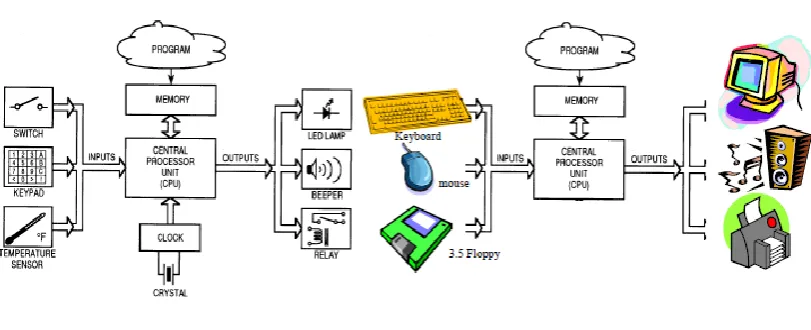
Configuration where the threshold configuration where the threshold determined and the values ofhe thresholds. The robot follows the human using a camera and the image of LEDs obtained from camera mounted on the robot. Typical structures of a microcontroller and personal computer system
Global Position System Illustration
Beacon Based Positioning for office equipment The flow chart of project implementation Ultrasonic principles
Ultrasonic Tx and Rx Principles
(a) Ultrasonic wave propagation (b)ultrasonic sensor frequency (c) ultrasonic sensor directivity
IR encoder.
Remote control Decoder Control Pulse Generator
Figure 3.8 Figure 3.9 Figure 3.10 Figure 3.11 Figure 3.12 Figure 3.13 Figure 3.14 Figure 3.15 Figure 3.16 Figure 3.17 Figure 3.18 Figure 3.19 Figure 3.20 Figure 3.21 Figure 3.22 Figure 3.23 Figure 3.24 Figure 3.25 Figure 3.26 Figure 3.27 Figure 3.28 Figure 3.29 Figure 3.30 Figure 3.31 Figure 3.32 Figure 3.33 Figure 3.34
40Khz Pulse Generator Ultrasonic driver Circuit Ultrasonic driver Circuit Inverting Amplifier Detection Circuit Sensor positioning
(a) middle sensor ON, (b) right sensor ON, (c) Left sensor ON ,(d) Robot turn until middle sensor ON Detection Algorithm Trialation Triangulation IFC Card IFC-MB00 IFC-PC00 IFC-CP04 IFC-BL02 IFC-DI08 IFC-AI08
Brusless DC Motor.
Mobile Robot Following System.
Block Diagram of 2 Basic Control system on/off Controller
Block Diagram of a PID control system
step response waveforms of a system with high and low Kp gain constants
step response waveforms of a system with tuned Kp value and Ki Constant.
Following robot signal interaction Flow Chart for Follower Robot
Flow chart of following robot movementUltrasonic
Figure 4.1 Figure 4.2 Figure 4.3 Figure 4.4 Figure 4.5 Figure 4.6 Figure 4.7 Figure 4.8 Figure 4.9 Figure 4.10 Figure 4.11 Figure 4.12 Figure 4.13 Figure 4.14 Figure 4.15 Figure 4.16 Figure 4.17 Figure 4.18 Figure 4.19 Figure 4.20 Figure 4.21 Figure 4.22 Figure 4.23 Figure 4.24 Figure 4.25 Figure 4.26 Figure 4.27 Figure 4.28 Figure 4.29 Transmitter circuit
PCB layout for Ultrasonic Transmitter Beacon Result for Ultrasonic TX Output
40 Khz sonic Burst
Operating region of transistor
Ultrasonic Receiver Circuit Diagram
Time Domain(Transient) simulation in Proteus Simulation Result in Proteu
(a)Output before rectifier (b) Output After rectifier HT 12E block diagram
Transmission timing for the HT12E Flow chart fot HT12E
Oscillator Frequency vs. Supply Voltage
IR Encoder Schematic Diagram
Simulation result on astable timer output 38KHz PCB layout fo IR Encoder
Address testing for IR encoder
Address Carried by 38KHz Carrier Frequency HT 12D block diagram
Timing diagram for HT12D Flow chart for HT12D
IR Decoder Schematic Diagram PCB layout fo IR Decoder
Address Carried by 38KHz Carrier Frequency Signal Received at HT12D
Graph for Sensor detection testing Source code for Sensor comparasion Graph for Sensor detection testing Source code for PID variable selection
Figure4.30 Figure 4.31 Figure 4.32 Figure 4.33
Program for PID updated value IR and Ultrasonic Transmitter Receiver sensors front View Overall system
LIST OF ABBREVIATION
A Ampere
B Binary
CPU Central Processing Unit
D Decimal
GPS Global Positioning System
I Current
IFC Interface Free Card LED Light Emitting Diode
MC Microcontroller
PC Personal Computer
R Resistance
RF Radio Frequency
RAM Random Access Memory
ROM Read Only Memory
V Volt
H Hexadecimal
AC Alternating Current
DC Direct Current
PIC Programmable Interface Controller PID Proportional Integral Derivative IFC Interface free Card
IR Infrared
IRR Infrared Receiver
TX Transmitter
LIST OF APPENDICES
A C-18 Program For Multi User Mobile Robot Following System
CHAPTER I
INTRODUCTION
1.1 Project Overview
[Type text]
1.2 Introduction
[Type text]
obtain its current position relative to the target before it makes decision on how to follow the target. “Localization” or knowledge of its current location is calculated by
one or more means, using sensors such as motor encoder, vision, laser or sonar sensors. There are many vision systems being built to track and follow the target effectively. The method can be seen in [11], [12] and [13].
1.3 Problem Statement:
[Type text]
1.4 Objective
The main objective is to design and implement the mobile robot following system using an IR encoder/decoder/ and ultrasonic beacon positioning system, equipped on the IFC mobile robot. There are 3 main objectives, at least to be achieved during the time frame of the project as follows:-
1. To design and construct an autonomous following robot system. 2. To integrate the concept of selected leader/follower behavior. 3. To improve the capability of the mobile robot in performing the
following task smoothly by Programming a PID controller in the system.
1.5 Scope of work
The project will be done by limiting the scopes into four (4). The scopes are as follows:
1. The working model will only use IR encoder/decoder channel.
2. This mobile robot can be only move in linear platform.
3. Detection of target distance is 0 to 3 meters.
[Type text]
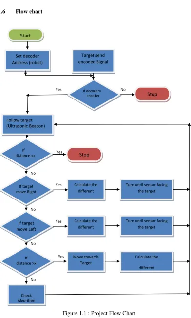
1.6 Flow chart
Figure 1.1 : Project Flow Chart
If decoder= encoder Set decoder Address (robot) Follow target (Ultrasonic Beacon) Start If distance <x If target move Right If target move Left If distance >x Check Algorithm Stop Calculate the different Calculate the different Calculate the different Move towards Target
Turn until sensor facing the target Turn until sensor facing
[Type text]
CHAPTER 2
LITERATURE REVIEW
2.1 Background
[Type text]
2.2 Literature related to area of study
2.2.1 Sensor Based Approach
A non-vision based approach uses several kinds of rangefinders, such as sonar sensors, infrared sensors, and others. Each rangefinder on the robot can determine the distance between the nearest object and the rangefinder itself. Because the robot is not able to distinguish between object and target person, this approach can only be adopted to implement either obstacle avoidance when regarding all the objects as obstacles or person-tracking when the target person is always the nearest object to the robot without any obstacle in between [1-10].
2.2.2. Transmitter and receiver Based Approach
Using a transmitter and receiver approach, the transmitters located on the target person transmit signals, such as ultrasonic waves or blinking LED. The receivers located on the mobile robot receive these signals. After computing the distance and the angle of the target from those signals, the robot knows where to move in order to turn itself toward the target person and decrease the distance in between. In [1], [5], [6] a transmitter and receiver based approaches have been discussed.
2.2.3 Following System Using Infrared based Approach
The main method in following system is potential field method, where the follower was “attracted” to the target and was “pushed away” from the obstacles [7]. Using an
[Type text]
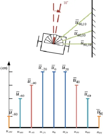
transmitter is placed in front and along with the axis of the cylinder, which confirms the directional property of the light. The detection range of the receiver can be adjusted by placing the side walls around the receiver. One of the simplest methods to deploy several receivers to cover the front 180-degree detection range is to equally divide the detection range by the number of the utilized receivers, just like slicing the cake [1] as shown in figure 2.1 and 2.2.
Figure 2.1 Configuration of nine ultrasonic range finders installed on the follower
[Type text]
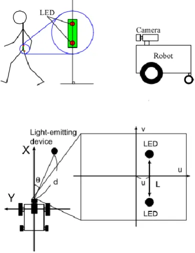
2.2.4 Following System Using Blinking LED Devices
This approach requires equipping the target person with two infrared LED devices with fixed distance between them and using a camera on the robot to detect the two devices. This is similar to the vision-based approach. The main difference is that the signals from infrared LED devices should be firmer and not affected by the disturbance in the environment, as long as they are not blocked by any obstacle. The camera is able to rotate to keep the target person in the middle of the image. By computing the distance between two LED lights and the deviation of the two lights from the central vertical axis in the image, the range and the bearing of the target person can be obtained respectively by the robot [8] as shown in figure 2.3.
[Type text]
2.2.5. Following System Using an Ultrasonic Positioning System
This approach is to equipped the ultrasonic transmitters on the target person and the receivers on the robot. By computing the time interval between transmitting and receiving the ultrasonic signal, the distance between the target person and the robot will be determined. The angle can also be computed from the time delay between several receivers. These approaches are straight-forward for person-tracking, but they are not suitable when there are obstacles between the target person and the robot. The detection of obstacles will be a problem using these approaches. Without any additional mechanism, the robot is not able to implement obstacle avoidance. [2]
2.2.6 Following System using Intelligent Space Approach
[Type text]
2.2.7 Following Systems Using Combined/Multi-Mode Approach
A combined/multi-modal approach is made of a combination of several approaches. It is able to gather the advantages of each single approach. This is also the key subject in this thesis. By using an ultrasonic positioning system along with the IR decoders, this research combines the transmitter-and-receiver based approach with the non-vision based approach. A suitable algorithm also will be designed to adapt the robot to several situations that may happen in the implementation of person-tracking. The robot can then accomplish the person-tracking tasks, which include person-following and obstacle avoidance in unstructured environments [6].
2.2.8 Microcontroller
[Type text]
Following are the reasons why microcontrollers are incorporated in this control systems:
a. Cost: Microcontrollers with the supplemantary circuit components are much
cheaper than a computer with an analog and digital I/O.
b. Size and Weight: Microcontrollers are compact and light compared to
computers.
c. Simple applications: If the application requires very few number of I/O and
the code is relatively small, which do not require extended amount of memory and a simple LCD display is sufficient as a user interface, a microcontroller would be suitable for this application.
d. Reliability: Since the architecture is much simpler than a computer it is less
likely to fail.
e. Speed: All the components on the microcontroller are located on a singe piece
of silicon. Hence, the applications run much faster than it does on a computer.
[Type text] 2.2.9 GPS
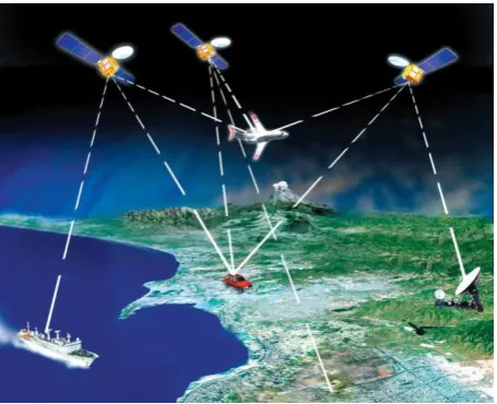
[image:31.595.207.435.488.673.2]Global Position Systems are widely becoming the position system of choice for autonomous navigation. This technology allows for an agent to determine its location using broadcasted signals from satellites overhead. The Global Positioning System associated with the United States is maintained by the Department of Defense to providea positioning service for use by the US military [17]. Since its creation, the service hasbeen used for commercial purposes such as nautical, aeronautical, and ground based navigation, and land surveying. The current US based GPS satellite constellation system consists of a 24-satellite system. The number of satellites for this system can vary due to satellites being taken in and out of service. Other countries are leading efforts to developalternative satellite systems for their own GPS systems. A similar GPS systems is the GLONASS constructed by Russia [17]. Each satellite maintains its own specific orbit and circumnavigates earth once every 12 hours. The orbit of each satellite is timed and coordinated so that five to eight satellites are above the horizon of any location on the surface of earth at any time. Figure 2.5 illustrates the manner by which an autonomous vehicle determines its’ position using GPS.
[Type text]
2.2.9.1 Position Solution
A GPS receiver calculates position by first receiving the microwave RF signals broadcast by each visible satellite [17]. The signals broadcasted by the satellites are complex high frequency signals with encoded binary information. The encoded binary data contains a large amount of information but mainly contains information about the time that the data was sent and location of the satellite in orbit. The GPS receiver processes this information to solve for its position and current time.
2.2.9.2 Accuracy and Update Rate
[Type text]
Currently this system only covers most of North America. This type of system has been used in research and position solutions with errors of less than three meters have been observed.
2.2.10 Beacon Based Position Systems
[Type text]
CHAPTER 3
METHODOLOGY
3.1 Background
[Type text]
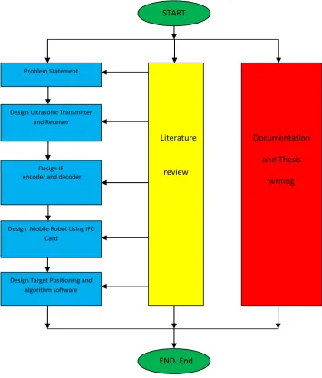
Figure 3.1: The flow chart of project implementation
3.2 Ultrasonic, encoder and detector :
3.2.1 Ultrasonic principle:
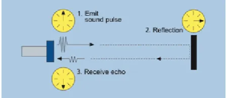
Ultrasonic sensors emit short, high-frequency sound pulses at regular intervals. These propagate in the air at the velocity of sound. If they strike an object, then they are reflected back as echo signals to the sensor, which itself computes the distance to the target based on the time-span between emitting the signal and receiving the echo, refer to figure 3.2.
Documentation
and Thesis
writing Literature
review
Problem Statement
Design Ultrasonic Transmitter and Receiver
Design IR encoder and decoder
Design Mobile Robot Using IFC Card
Software
Decoder Design Target Positioning and
algorithm software
START Start
[Type text]
Figure 3.2 Ultrasonic principle
[Type text]
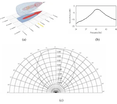
Figure 3.3 Ultrasonic Tx and Rx Principles
(a) (b)
(c)
[Type text]
3.2.2 Encoder design:
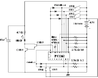
An encoder is a circuit that accepts an active level on one of its inputs, representing digit, such as a decimal or octal digits, and converts it to a coded output such as BCD or binary. Encoders can also be devised to encode various symbols and alphabetic characters. The process of converting from familiar symbols or numbers to a coded format is called encoding. Figure 3,5 shows the IR encoder.
Figure 3.5 IR encoder
3.2.3 Decoder design:
[Type text]
; all other outputs remain inactive. In its general form, a decoder has N input lines to handle N bits and form one to 2 N address lines to indicate the presence of one or more N-bit combinations. Fig 3.6 shows the IR decoder.
Figure 3.6 Remote control Decoder
3.3 Ultrasonic Transmitter design
Figure 3.7:Control Pulse Generator
[Type text]
The time of the oscillation pulse can be calculated by the following formula. Actually, with the error of the parts, it is different from the calculation a little.
The condition : RA = 1M-ohm, RB = 15K-ohm, C = 0.1µF
TL = 0.69 x RB x C
= 0.69 x 15 x 103 x 0.1 x 10-6 = 1 x 10-3
= 1 msec
TH = 0.69 x ( RA + RB ) x C
= 0.69 x 1015 x 103 x 0.1 x 10-6 = 70.0 x 10-3
= 70 msec
Figure 3.8: 40Khz Pulse Generator
REFERENCE
[1] Youg Jen Wen., “ Infrared Sensor Based Target Following Device for a Mobile Robot” IEEE/ASME International Conference on Advanced
Intelligent Mechatronics ,(AIM2011), 2001.
[2] Ivan Paunović., “Calibration of Ultrasonic Sensors of a Mobile
Robot”SERBIAN JOURNAL OF ELECTRICAL ENGINEERING Vol. 6, ,
December 2009. No. 3, 427 – 437.
[3] Jwu-ShengHu., “Design of Sensing System and Anticipative Behavior for Human Following of Mobile Robots” IEEE TRANSACTIONS ON
INDUSTRIAL ELECTRONICS,VOL.61,NO.4, 2014.
[4] Guansheng Xing., “People-following System Design for Mobile Robots Using Kinect Sensor” 25th
Chinese Control and Decision Conference(CCDC) , 2013
[5] Quoc Khanh Dang and Young Soo Suh.,“Human-following robot using infrared camera” 11th International Conference on Control, Automation
and Systems KINTEX, Gyeonggi-do, Korea, 2011.
[6] Marin Kobilarov., “People tracking and following with mobile robot using an omnidirectional camera and a laser” Proceedings of the IEEE
International Conference on Robotics and Automation Orlando, Florida , 2006.
[8] Akihisa Ohya., “ Intelligent Escort Robot moving together with human– HUMANFOLLOWINGBEHAVIOR–PRESTO, JST / University of Tsukuba, Japan, 2007.
[9] Kazuyuki Morioka., “Physical Agent for Human Following in Intelligent Sensor Network.” Proceedings of the IEEE/RSJ International Conference on Intelligent Robots and Systems, pp. 12341239, EPFL, Lausanne,
Switzerland. 2002.
[10] Kazuyuki Morioka., “Human-Following Mobile Robot in a Distributed Intelligent Sensor Network.” IEEE Transactions on Industrial Electronics,
Vol. 51, No. 1. 2004.
[11] Jo˜ao Sequeira and Andr´e Gonc¸alves, Andr´e Godinho., “ Low cost Sensing For Autonomous Car Driving In Highways”. 2007.
[12] Rahul Sukthankar., “ RACCOON: A Real-time Autonomous Car Chaser Operating Optimally at Night”. 2008.
[13] J. Giesbrecht and DRDC Suffield., “ Leader/Follower Behaviour Using the SIFT Algorithm for Object Recognition”. 2006.
[14] Oreback., “ Component Framework for Autonomous Mobile Robots.” Doctoral Thesis,Stockholm Sweden, 2004.
[15] Ngo, T. D., Raposo, H., Schioler, H. Being Sociable., “ Multirobots with Selfsustained Energy”. Proceedings of the 15th IEEE Mediterranean
[16] Center for Advanced Aviation Systems Development, The MITRE Corporation,“Navigation,” 2/25/2002, from
www.caasd.org/work/navigation.html,
[17] Dana, P. H., “Global Positioning System Overview,” 5/1/2001, from http://www.colorado.edu/geography/gcraft/notes/gps/gps.html,
[18] Federal Aviation Administration “Wide Area Augmentation System,”2003 from http://gps.faa.gov/Programs/WAAS/waas.htm,
[19] Howell, Elizabeth. "Navstar: GPS Satellite Network". Retrieved February 14, 2013.from http://space.com
[20] Haykin, S., Array Signal Processing, Prentice Hall Inc., Englewood Cliffs, New Jersey, 1985.